

Owners Manual
Page 2
... 6 Preparing remote control 7 Controls and functions 8 PREPARATIONS 11 General setup procedure 11 a Installation 12 b Connecting a TV 22 c Connecting playback devices 23 d Other connections 25 Connecting a subwoofer 25 Wired network connections 25 e Connecting the power cable 26 f Initial settings 27 Displaying the menu screen on the TV 27 Selecting the language for...
... 6 Preparing remote control 7 Controls and functions 8 PREPARATIONS 11 General setup procedure 11 a Installation 12 b Connecting a TV 22 c Connecting playback devices 23 d Other connections 25 Connecting a subwoofer 25 Wired network connections 25 e Connecting the power cable 26 f Initial settings 27 Displaying the menu screen on the TV 27 Selecting the language for...

Owners Manual
Page 4
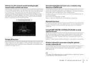
...-party manufactures) Audio HDMI Control Audio TV remote control Audio/ Video* Audio The unit Control HDMI Control Audio/ Video* Wireless subwoofer kit SWK-W16 (optional) This unit's remote control BD/DVD player * Supports 4K video and HDCP version 2.2 Mobile devices ... Reproducing stereo or multichannel sounds with enhanced sound (Compressed Music Enhancer) . p. 61 Dedicated apps for the listening room setup . p. 34 Subwoofer (optional or available from Bluetooth® devices . FEATURES What you can do with this unit Sound beams are reflected off walls and a...
...-party manufactures) Audio HDMI Control Audio TV remote control Audio/ Video* Audio The unit Control HDMI Control Audio/ Video* Wireless subwoofer kit SWK-W16 (optional) This unit's remote control BD/DVD player * Supports 4K video and HDCP version 2.2 Mobile devices ... Reproducing stereo or multichannel sounds with enhanced sound (Compressed Music Enhancer) . p. 61 Dedicated apps for the listening room setup . p. 34 Subwoofer (optional or available from Bluetooth® devices . FEATURES What you can do with this unit Sound beams are reflected off walls and a...
Owners Manual
Page 5
... You can receive and play audio from the center speakers, as needed. This app also allows you can be established using the optional wireless subwoofer kit (SWK-W16) (p. 25). • In this feature can do with this unit En 5 Using HOME THEATER CONTROLLER (WLAN) to...Lift function When playing movies, this manual, iOS and Android mobile devices are installed behind the screen, allowing for details. Wireless subwoofer connection using MusicCast CONTROLLER The free dedicated app for synchronized playback. Bluetooth functions You can also transmit audio input to the unit to...
... You can receive and play audio from the center speakers, as needed. This app also allows you can be established using the optional wireless subwoofer kit (SWK-W16) (p. 25). • In this feature can do with this unit En 5 Using HOME THEATER CONTROLLER (WLAN) to...Lift function When playing movies, this manual, iOS and Android mobile devices are installed behind the screen, allowing for details. Wireless subwoofer connection using MusicCast CONTROLLER The free dedicated app for synchronized playback. Bluetooth functions You can also transmit audio input to the unit to...
Owners Manual
Page 9
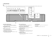
... audio output jacks (p. 24). 4 AUX2 digital coaxial input jack For connecting to a network with a digital coaxial audio output jack (p. 24). SYSTEM SUBWOOFER CONNECTOR OUT R L AUX1 AUX2 TV OPTICAL IR-IN IR-OUT UPDATE ONLY RS-232C NETWORK 5 TV and OPTICAL jacks For connecting to a playback...IN 2 IN 3 8 IN 1 (HDCP2.2) IN 2 IN 3 IN 4 HDMI OUT (ARC) IN 4 HDMI OUT (ARC) 9 0 NETWORK AC IN a 1 SYSTEM CONNECTOR jack Connect to a Yamaha subwoofer so that the HDMI and NETWORK jacks may be easily located, the illustration of the rear of the unit used in this unit's firmware (p. 87...
... audio output jacks (p. 24). 4 AUX2 digital coaxial input jack For connecting to a network with a digital coaxial audio output jack (p. 24). SYSTEM SUBWOOFER CONNECTOR OUT R L AUX1 AUX2 TV OPTICAL IR-IN IR-OUT UPDATE ONLY RS-232C NETWORK 5 TV and OPTICAL jacks For connecting to a playback...IN 2 IN 3 8 IN 1 (HDCP2.2) IN 2 IN 3 IN 4 HDMI OUT (ARC) IN 4 HDMI OUT (ARC) 9 0 NETWORK AC IN a 1 SYSTEM CONNECTOR jack Connect to a Yamaha subwoofer so that the HDMI and NETWORK jacks may be easily located, the illustration of the rear of the unit used in this unit's firmware (p. 87...
Owners Manual
Page 10
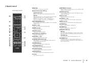
A 3D SURROUND key Switch to stereo playback mode (p. 40). G VOL (+/-) key Adjust the volume of the subwoofer (p. 36). 5 MUTE ( ) key Mute the sound (p. 36). 6 SETUP ( ) key Display the setup menu (p. 66). 7 S/T/W/X keys, ENTER key Change the setting (p. 66). 8 RETURN ( ) key Return to ...
A 3D SURROUND key Switch to stereo playback mode (p. 40). G VOL (+/-) key Adjust the volume of the subwoofer (p. 36). 5 MUTE ( ) key Mute the sound (p. 36). 6 SETUP ( ) key Display the setup menu (p. 66). 7 S/T/W/X keys, ENTER key Change the setting (p. 66). 8 RETURN ( ) key Return to ...
Owners Manual
Page 11
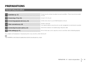
...) 2 Connecting a TV (p. 22) 3 Connecting playback devices (p. 23) 4 Other connections (p. 25) 5 Connecting the power cable (p. 26) 6 Initial settings (p. 27) Position the unit to the unit. Connect a subwoofer. Connect a TV to achieve the optimal surround sound effects. Perform initial setup, such as BD/DVD players) to a router in the power cable. This completes...
...) 2 Connecting a TV (p. 22) 3 Connecting playback devices (p. 23) 4 Other connections (p. 25) 5 Connecting the power cable (p. 26) 6 Initial settings (p. 27) Position the unit to the unit. Connect a subwoofer. Connect a TV to achieve the optimal surround sound effects. Perform initial setup, such as BD/DVD players) to a router in the power cable. This completes...

Owners Manual
Page 22
... an optical cable. PREPARATIONS ➤ b Connecting a TV En 22 HDMI OUT (ARC) jack IN 1 (HDCP2.2) IN 2 IN 3 IN 4 HDMI OUT (ARC) OUT (ARC) SYSTEM SUBWOOFER CONNCETOR OUT R L AUX1 AUX2 TV OPTICAL IR-IN IR-OUT UPDATE ONLY RS-232C The unit (rear) NETWORK HDMI ARC-compatible HDMI input HDMI (ARC... via an audio cable as well as an HDMI cable. HDMI OUT (ARC) jack IN 1 (HDCP2.2) IN 2 IN 3 IN 4 HDMI OUT (ARC) SYSTEM SUBWOOFER CONNCETOR OUT R L AUX1 AUX2 TV OPTICAL IR-IN IR-OUT UPDATE ONLY RS-232C The unit (rear) OUT HDMI (ARC) O NETWORK TV TV jack HDMI...
... an optical cable. PREPARATIONS ➤ b Connecting a TV En 22 HDMI OUT (ARC) jack IN 1 (HDCP2.2) IN 2 IN 3 IN 4 HDMI OUT (ARC) OUT (ARC) SYSTEM SUBWOOFER CONNCETOR OUT R L AUX1 AUX2 TV OPTICAL IR-IN IR-OUT UPDATE ONLY RS-232C The unit (rear) NETWORK HDMI ARC-compatible HDMI input HDMI (ARC... via an audio cable as well as an HDMI cable. HDMI OUT (ARC) jack IN 1 (HDCP2.2) IN 2 IN 3 IN 4 HDMI OUT (ARC) SYSTEM SUBWOOFER CONNCETOR OUT R L AUX1 AUX2 TV OPTICAL IR-IN IR-OUT UPDATE ONLY RS-232C The unit (rear) OUT HDMI (ARC) O NETWORK TV TV jack HDMI...

Owners Manual
Page 23
...HDMI 1-4 using the OPTICAL key on the remote control. The unit (rear) IN 1 (HDCP2.2) IN 2 IN 3 IN 4 HDMI OUT (ARC) O SYSTEM SUBWOOFER CONNCETOR OUT R L AUX1 AUX2 TV OPTICAL IR-IN IR-OUT UPDATE ONLY OPTICAL NETWORK RS-232C OPTICAL jack Video device To video output jack OPTICAL... O Audio output (digital optical) 1. Remove the cap 2. The unit (rear) IN 1 (HDCP2.2) IN 2 IN 3 IN 4 HDMI OUT (ARC) SYSTEM SUBWOOFER CONNCETOR OUT R L AUX1 AUX2 TV OPTICAL IR-IN IR-OUT UPDATE ONLY RS-232C IN 1 (HDCP2.2) IN 2 NETWORK IN 3 IN 4 HDMI IN 1-4 jacks HDMI ...
...HDMI 1-4 using the OPTICAL key on the remote control. The unit (rear) IN 1 (HDCP2.2) IN 2 IN 3 IN 4 HDMI OUT (ARC) O SYSTEM SUBWOOFER CONNCETOR OUT R L AUX1 AUX2 TV OPTICAL IR-IN IR-OUT UPDATE ONLY OPTICAL NETWORK RS-232C OPTICAL jack Video device To video output jack OPTICAL... O Audio output (digital optical) 1. Remove the cap 2. The unit (rear) IN 1 (HDCP2.2) IN 2 IN 3 IN 4 HDMI OUT (ARC) SYSTEM SUBWOOFER CONNCETOR OUT R L AUX1 AUX2 TV OPTICAL IR-IN IR-OUT UPDATE ONLY RS-232C IN 1 (HDCP2.2) IN 2 NETWORK IN 3 IN 4 HDMI IN 1-4 jacks HDMI ...

Owners Manual
Page 24
The unit (rear) IN 1 (HDCP2.2) IN 2 IN 3 IN 4 HDMI OUT (ARC) SYSTEM SUBWOOFER CONNCETOR OUT R L AUX1 AUX2 TV OPTICAL IR-IN IR-OUT UPDATE ONLY RS-232C NETWORK AUX1 (analog) jacks R L AUX1 R L TV To video output jack Audio ... the unit by switching input to this unit via a stereo cable (not supplied). The unit (rear) IN 1 (HDCP2.2) IN 2 IN 3 IN 4 HDMI OUT (ARC) SYSTEM SUBWOOFER CONNCETOR OUT R L AUX1 AUX2 TV OPTICAL IR-IN IR-OUT UPDATE ONLY RS-232C NETWORK C AUX2 AUX2 (digital coaxial) jack TV To video output jack...
The unit (rear) IN 1 (HDCP2.2) IN 2 IN 3 IN 4 HDMI OUT (ARC) SYSTEM SUBWOOFER CONNCETOR OUT R L AUX1 AUX2 TV OPTICAL IR-IN IR-OUT UPDATE ONLY RS-232C NETWORK AUX1 (analog) jacks R L AUX1 R L TV To video output jack Audio ... the unit by switching input to this unit via a stereo cable (not supplied). The unit (rear) IN 1 (HDCP2.2) IN 2 IN 3 IN 4 HDMI OUT (ARC) SYSTEM SUBWOOFER CONNCETOR OUT R L AUX1 AUX2 TV OPTICAL IR-IN IR-OUT UPDATE ONLY RS-232C NETWORK C AUX2 AUX2 (digital coaxial) jack TV To video output jack...
Owners Manual
Page 25
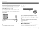
... not be connected to the unit via a wireless connection. The unit and the wireless subwoofer kit are two ways to connect a subwoofer to the unit: use a third-party RCA monaural cable, or use with the unit. When connecting a Yamaha subwoofer equipped with a system connector, connect a system control cable (or third-party 3.5mm monaural mini...
... not be connected to the unit via a wireless connection. The unit and the wireless subwoofer kit are two ways to connect a subwoofer to the unit: use a third-party RCA monaural cable, or use with the unit. When connecting a Yamaha subwoofer equipped with a system connector, connect a system control cable (or third-party 3.5mm monaural mini...

Owners Manual
Page 26
123456 e Connecting the power cable After all the connections are complete, plug in the power cable. The unit (rear) AC IN IN 1 (HDCP2.2) IN 2 IN 3 IN 4 HDMI OUT (ARC) SYSTEM SUBWOOFER CONNCETOR OUT R L AUX1 AUX2 TV OPTICAL IR-IN IR-OUT UPDATE ONLY RS-232C To an AC wall outlet PREPARATIONS ➤ e Connecting the power cable En 26
123456 e Connecting the power cable After all the connections are complete, plug in the power cable. The unit (rear) AC IN IN 1 (HDCP2.2) IN 2 IN 3 IN 4 HDMI OUT (ARC) SYSTEM SUBWOOFER CONNCETOR OUT R L AUX1 AUX2 TV OPTICAL IR-IN IR-OUT UPDATE ONLY RS-232C To an AC wall outlet PREPARATIONS ➤ e Connecting the power cable En 26

Owners Manual
Page 27
...cancel menu display. Setup Menu Beam Sound HDMI Display Information IntelliBeam Horizontal Angle Vertical Angle Beam Travel Length Focal Length Image Location Channel Out Subwoofer • The setup menu (p. 66) can only be shown in the front panel display. TV remote control (example) Switch input ...sources The unit (rear) IN 1 (HDCP2.2) IN 2 IN 3 IN 4 HDMI OUT (ARC) SYSTEM SUBWOOFER CONNCETOR OUT R L AUX1 AUX2 TV OPTICAL IR-IN IR-OUT UPDATE ONLY RS-232C NETWORK OUT (ARC) HDMI TV HDMI INPUT 1 2 3 HDMI The...
...cancel menu display. Setup Menu Beam Sound HDMI Display Information IntelliBeam Horizontal Angle Vertical Angle Beam Travel Length Focal Length Image Location Channel Out Subwoofer • The setup menu (p. 66) can only be shown in the front panel display. TV remote control (example) Switch input ...sources The unit (rear) IN 1 (HDCP2.2) IN 2 IN 3 IN 4 HDMI OUT (ARC) SYSTEM SUBWOOFER CONNCETOR OUT R L AUX1 AUX2 TV OPTICAL IR-IN IR-OUT UPDATE ONLY RS-232C NETWORK OUT (ARC) HDMI TV HDMI INPUT 1 2 3 HDMI The...
Owners Manual
Page 30
...possible. After [ENTER] is displayed after connecting IntelliBeam microphone to improve sound reflection. 2. For accurate measurement, turn on . • When a subwoofer is as quiet as shown below and then leave the room. AUTO SETUP (PREPARATION & CHECK) Please connect the MIC. Sound optimize only This ... of the listening environment. Run "Sound optimize only" (p. 32). • Make sure that the parameter best matches your TV on the subwoofer, and set at least 1.8m/6ft away from this unit (p. 27). 3 Connect the IntelliBeam microphone to the unit, turn off air ...
...possible. After [ENTER] is displayed after connecting IntelliBeam microphone to improve sound reflection. 2. For accurate measurement, turn on . • When a subwoofer is as quiet as shown below and then leave the room. AUTO SETUP (PREPARATION & CHECK) Please connect the MIC. Sound optimize only This ... of the listening environment. Run "Sound optimize only" (p. 32). • Make sure that the parameter best matches your TV on the subwoofer, and set at least 1.8m/6ft away from this unit (p. 27). 3 Connect the IntelliBeam microphone to the unit, turn off air ...

Owners Manual
Page 31
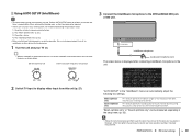
ENVIRONMENT CHECK:Success FRONT :Beam SURROUND :Beam SUBWOOFER:Wired [ENTER]:Save set-up. [RETURN]:Do not save several measurement results by pressing the SYSTEM MEMORY 1, 2, or 3 key. When the SYSTEM MEMORY 1 key is ...
ENVIRONMENT CHECK:Success FRONT :Beam SURROUND :Beam SUBWOOFER:Wired [ENTER]:Save set-up. [RETURN]:Do not save several measurement results by pressing the SYSTEM MEMORY 1, 2, or 3 key. When the SYSTEM MEMORY 1 key is ...

Owners Manual
Page 33
...microphone is not placed in your listening room. Please check the connection with this unit and begin measurement again. The subwoofer output signals cannot be set in front of more than expected. Please check MIC connection and re-try . Confirm the connection... between the wireless subwoofer kit and subwoofer (p. 25), and begin measurement again. Some other operations with subwoofer. Do not perform any other operations were performed on . Please check MIC position. Please check...
...microphone is not placed in your listening room. Please check the connection with this unit and begin measurement again. The subwoofer output signals cannot be set in front of more than expected. Please check MIC connection and re-try . Confirm the connection... between the wireless subwoofer kit and subwoofer (p. 25), and begin measurement again. Some other operations with subwoofer. Do not perform any other operations were performed on . Please check MIC position. Please check...

Owners Manual
Page 36
... key again or press VOL (+/ -) key. "MUTE OFF" is shown in the front panel display. • The subwoofer volume can be adjusted separately from the whole volume. • Lowering the subwoofer volume is output from a Bluetooth device, refer to turn on this unit. 2 Turn on devices (TV, BD/DVD ...Input source name For playback from both TV speaker and this unit, mute the TV sound. • When sound input to the connection of the subwoofer. • When audio is recommended at night. 6 Select 3D surround playback, surround playback, stereo playback, or target playback mode, and configure ...
... key again or press VOL (+/ -) key. "MUTE OFF" is shown in the front panel display. • The subwoofer volume can be adjusted separately from the whole volume. • Lowering the subwoofer volume is output from a Bluetooth device, refer to turn on this unit. 2 Turn on devices (TV, BD/DVD ...Input source name For playback from both TV speaker and this unit, mute the TV sound. • When sound input to the connection of the subwoofer. • When audio is recommended at night. 6 Select 3D surround playback, surround playback, stereo playback, or target playback mode, and configure ...

Owners Manual
Page 42
...-20 to increase the level. C: Center SL/SR: Surround (left ) or HR (height right) to increase the level. • The volume of the subwoofer also can be adjusted by using the SUB (+/-) key. • Adjusting the channel level is not available in their respective directions. • Refer to "Channel ... channel from the followings. When the sound is not like surround sound: Select SL (surround left), SR (surround right), HL (height left /right) SW: Subwoofer 2 Press the S/T key to adjust the volume. FL: Front left FR: Front right C: Center SL: Surround left FL HL FR C SW HR SR:...
...-20 to increase the level. C: Center SL/SR: Surround (left ) or HR (height right) to increase the level. • The volume of the subwoofer also can be adjusted by using the SUB (+/-) key. • Adjusting the channel level is not available in their respective directions. • Refer to "Channel ... channel from the followings. When the sound is not like surround sound: Select SL (surround left), SR (surround right), HL (height left /right) SW: Subwoofer 2 Press the S/T key to adjust the volume. FL: Front left FR: Front right C: Center SL: Surround left FL HL FR C SW HR SR:...

Owners Manual
Page 43
...source ("BLUETOOTH", or the name of the front panel display is minimized and the maximum volume is connected to the unit. - None: No subwoofer is reduced. 1 Press the ECO key. When this function is enabled, the brightness of the connected device, is displayed. 1 Press the INFO... features Saving energy with Bluetooth input.) T Beam: Playback mode T Decoder: Current decoder (p. 75) T Cinema DSP: CINEMA DSP program (p. 38) T SUB Status: Subwoofer status T • Display in playback mode (Beam) - 3D SUR.: Playback in the setup menu is minimized. "ECO ON" is enabled, "Dimmer" in the ...
...source ("BLUETOOTH", or the name of the front panel display is minimized and the maximum volume is connected to the unit. - None: No subwoofer is reduced. 1 Press the ECO key. When this function is enabled, the brightness of the connected device, is displayed. 1 Press the INFO... features Saving energy with Bluetooth input.) T Beam: Playback mode T Decoder: Current decoder (p. 75) T Cinema DSP: CINEMA DSP program (p. 38) T SUB Status: Subwoofer status T • Display in playback mode (Beam) - 3D SUR.: Playback in the setup menu is minimized. "ECO ON" is enabled, "Dimmer" in the ...

Owners Manual
Page 44
... Load?" Example 1 Saving the IntelliBeam measurements for 3D surround/surround playback mode.) • Surround: CINEMA DSP 3D/CINEMA DSP (p. 38) • Tone control (p. 84) • Subwoofer settings (p. 73) Saving settings to system memory 1 Hold down the SYSTEM MEMORY 1, 2, or 3 key until "M1 Save?", "M2 Save?", or "M3 Save?", corresponding to load...
... Load?" Example 1 Saving the IntelliBeam measurements for 3D surround/surround playback mode.) • Surround: CINEMA DSP 3D/CINEMA DSP (p. 38) • Tone control (p. 84) • Subwoofer settings (p. 73) Saving settings to system memory 1 Hold down the SYSTEM MEMORY 1, 2, or 3 key until "M1 Save?", "M2 Save?", or "M3 Save?", corresponding to load...

Owners Manual
Page 51
... point). Internet Network Attached Storage (NAS) WAN LAN Modem Router Mobile device PC Network cable NETWORK IN 1 (HDCP2.2) IN 2 IN 3 IN 4 HDMI OUT (ARC) SYSTEM SUBWOOFER CONNCETOR OUT R L AUX1 AUX2 TV OPTICAL IR-IN IR-OUT UPDATE ONLY RS-232C The unit (rear) NETWORK • If the unit is connected to...
... point). Internet Network Attached Storage (NAS) WAN LAN Modem Router Mobile device PC Network cable NETWORK IN 1 (HDCP2.2) IN 2 IN 3 IN 4 HDMI OUT (ARC) SYSTEM SUBWOOFER CONNCETOR OUT R L AUX1 AUX2 TV OPTICAL IR-IN IR-OUT UPDATE ONLY RS-232C The unit (rear) NETWORK • If the unit is connected to...


