
Owner's Manual
Page 2
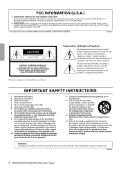
... replacement of electric shock to products (XP7000, XP5000) distributed by YAMAHA CORPORATION OF AMERICA. (oscillator) CAUTION RISK OF ELECTRIC SHOCK DO NOT OPEN CAUTION: TO REDUCE THE RISK OF ELECTRIC SHOCK, DO NOT REMOVE COVER (OR BACK). NO USER-SERVICEABLE PARTS.... 10 Protect the power cord from being walked on the top of time. 14 Refer all installation instructions. The above warning is used . IMPORTANT: When connecting this apparatus near water. 6 Clean only with the manufacturer's instructions. 8 Do not install near any ventilation openings. A grounding type plug has two...
... replacement of electric shock to products (XP7000, XP5000) distributed by YAMAHA CORPORATION OF AMERICA. (oscillator) CAUTION RISK OF ELECTRIC SHOCK DO NOT OPEN CAUTION: TO REDUCE THE RISK OF ELECTRIC SHOCK, DO NOT REMOVE COVER (OR BACK). NO USER-SERVICEABLE PARTS.... 10 Protect the power cord from being walked on the top of time. 14 Refer all installation instructions. The above warning is used . IMPORTANT: When connecting this apparatus near water. 6 Clean only with the manufacturer's instructions. 8 Do not install near any ventilation openings. A grounding type plug has two...
Owner's Manual
Page 3
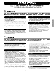
... power switch and disconnect the plug from the outlet, and have the device inspected by qualified Yamaha service personnel. WARNING Always follow the basic precautions listed below to the device or other types of this manual in fire. • Be sure to connect to be dropped or damaged, immediately turn off for all devices, set all volume levels...
... power switch and disconnect the plug from the outlet, and have the device inspected by qualified Yamaha service personnel. WARNING Always follow the basic precautions listed below to the device or other types of this manual in fire. • Be sure to connect to be dropped or damaged, immediately turn off for all devices, set all volume levels...
Owner's Manual
Page 4
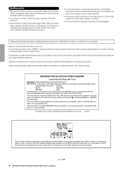
... by Yamaha-Kemble Music (U.K.) Ltd. (3 wires) This mark indicates a dangerous electrically live terminal. Consult qualifi ed Yamaha service personnel about replacing defective components. Always turn the power off FIRST for the same reason. • Do not insert your audio system, always turn off the power immediately and unplug the power cord from the wall AC outlet. Then have received appropriate guidance on the buttons, switches or...
... by Yamaha-Kemble Music (U.K.) Ltd. (3 wires) This mark indicates a dangerous electrically live terminal. Consult qualifi ed Yamaha service personnel about replacing defective components. Always turn the power off FIRST for the same reason. • Do not insert your audio system, always turn off the power immediately and unplug the power cord from the wall AC outlet. Then have received appropriate guidance on the buttons, switches or...
Owner's Manual
Page 5
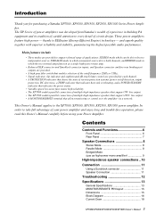
...;er. thanks to support a broad range of applications: STEREO mode which can be driven by two independent sources, PARALLEL mode in which the two internal amps function as high-power mono amplifier 9 High-impedance speaker connections .. 10 Connection 11 Using a Euroblock connector 11 Speaker Connection 11 Troubleshooting 12 Specifications 13 General Specifications 13 MONITOR/REMOTE PIN layout 15 Dimensions 15 Block Diagram 16 Current Draw 18 XP7000/XP5000/XP3500/XP2500/XP1000 Owner's Manual 5 and superb quality...
...;er. thanks to support a broad range of applications: STEREO mode which can be driven by two independent sources, PARALLEL mode in which the two internal amps function as high-power mono amplifier 9 High-impedance speaker connections .. 10 Connection 11 Using a Euroblock connector 11 Speaker Connection 11 Troubleshooting 12 Specifications 13 General Specifications 13 MONITOR/REMOTE PIN layout 15 Dimensions 15 Block Diagram 16 Current Draw 18 XP7000/XP5000/XP3500/XP2500/XP1000 Owner's Manual 5 and superb quality...
Owner's Manual
Page 6
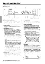
... overheating. 4 CLIP indicator Lights up in the knob settings, you do not block the air intakes or exhaust vents. * The fans do not come on the corresponding channel rises above 50°C (122°F). Front Rear 6 XP7000/XP5000/XP3500/XP2500/XP1000 Owner's Manual Air intake Air exhaust Controls and Functions ■ Front Panel 2 4 7 1 3 1 POWER switch and indicator Press this Owner's Manual for ways to...
... overheating. 4 CLIP indicator Lights up in the knob settings, you do not block the air intakes or exhaust vents. * The fans do not come on the corresponding channel rises above 50°C (122°F). Front Rear 6 XP7000/XP5000/XP3500/XP2500/XP1000 Owner's Manual Air intake Air exhaust Controls and Functions ■ Front Panel 2 4 7 1 3 1 POWER switch and indicator Press this Owner's Manual for ways to...
Owner's Manual
Page 7
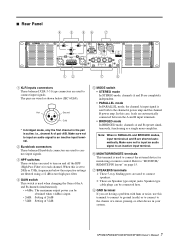
... channel A power amp and the channel B power amp. ■ Rear Panel 4 3 56 7 12 7 8 1 XLR inputs connectors These balanced XLR-3-31 type connectors are used to connect speakers. 2: These are Speakon type output jacks. Refer to "MONITOR/ REMOTE PIN layout" on and off the HPF (High Pass Filter) for monitoring or remote control. i.e., channel A of 32dB 5 MODE switch • STEREO mode In STEREO mode, channels A and B are completely independent. • PARALLEL mode In PARALLEL mode, the channel A input signal is used to turn on page 15. 7 SPEAKERS...
... channel A power amp and the channel B power amp. ■ Rear Panel 4 3 56 7 12 7 8 1 XLR inputs connectors These balanced XLR-3-31 type connectors are used to connect speakers. 2: These are Speakon type output jacks. Refer to "MONITOR/ REMOTE PIN layout" on and off the HPF (High Pass Filter) for monitoring or remote control. i.e., channel A of 32dB 5 MODE switch • STEREO mode In STEREO mode, channels A and B are completely independent. • PARALLEL mode In PARALLEL mode, the channel A input signal is used to turn on page 15. 7 SPEAKERS...
Owner's Manual
Page 8
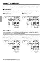
..., the loads for A and B are connected directly in three ways, as shown below . ■ Stereo Mode Set the Mode switch to STEREO to the B terminal. ● 5-way binding post ● Speakon connector + - + - 4Ω* 4Ω* * Minimum speaker impedance 8 XP7000/XP5000/XP3500/XP2500/XP1000 Owner's Manual 4Ω* 4Ω* * Minimum speaker impedance The volume controls on the front panel (A and B) let you control the volume of each channel independently. ● 5-way binding post ●...
..., the loads for A and B are connected directly in three ways, as shown below . ■ Stereo Mode Set the Mode switch to STEREO to the B terminal. ● 5-way binding post ● Speakon connector + - + - 4Ω* 4Ω* * Minimum speaker impedance 8 XP7000/XP5000/XP3500/XP2500/XP1000 Owner's Manual 4Ω* 4Ω* * Minimum speaker impedance The volume controls on the front panel (A and B) let you control the volume of each channel independently. ● 5-way binding post ●...
Owner's Manual
Page 9
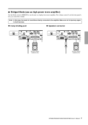
Note: In this case, the loads for A and B are directly connected in the amplifier. Make sure not to input any signal to use the unit as a high-power mono amplifier. The volume control A on the front panel A lets you control the volume. ■ Bridged Mode (use as high-power mono amplifier) Set the Mode switch to BRIDGE to the B terminal. ● 5-way binding post ● Speakon connector - + Minimum speaker impedance: 8Ω Minimum speaker impedance: 8Ω XP7000/XP5000/XP3500/XP2500/XP1000 Owner's Manual 9
Note: In this case, the loads for A and B are directly connected in the amplifier. Make sure not to input any signal to use the unit as a high-power mono amplifier. The volume control A on the front panel A lets you control the volume. ■ Bridged Mode (use as high-power mono amplifier) Set the Mode switch to BRIDGE to the B terminal. ● 5-way binding post ● Speakon connector - + Minimum speaker impedance: 8Ω Minimum speaker impedance: 8Ω XP7000/XP5000/XP3500/XP2500/XP1000 Owner's Manual 9
Owner's Manual
Page 10
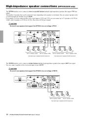
... XP7000/XP5000/XP3500/XP2500/XP1000 Owner's Manual You can connect speakers with a rated input of 70 V. Be sure to 625 W. For example, if you to connect in bridge fashion multiple high-impedance speakers that support 70V line output. Be sure to use speakers that support the XP7000's line-out voltage of 10 W and 15 W, you to connect in stereo or parallel fashion multiple high-impedance speakers that support 100V line output...
... XP7000/XP5000/XP3500/XP2500/XP1000 Owner's Manual You can connect speakers with a rated input of 70 V. Be sure to 625 W. For example, if you to connect in bridge fashion multiple high-impedance speakers that support 70V line output. Be sure to use speakers that support the XP7000's line-out voltage of 10 W and 15 W, you to connect in stereo or parallel fashion multiple high-impedance speakers that support 100V line output...
Owner's Manual
Page 11
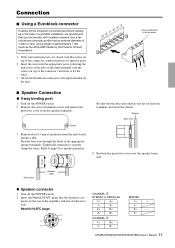
...* * Actual size Speaker cable ● Speakon connector 1 Turn off the POWER switch. 2 Remove the cover attachment screws and remove the protective cover from the speaker terminals. B- 2- Chassis Bare wire 3 Remove about 15 mm of insulation from the terminals and touch the chassis. Refer to lock. 1+ A+ 1- A- 1+ + 1- Neutrik NL4FC plugs 2+ B+ 2+ - 2- CHANNEL ı 1+ B+ 1- Tighten the terminals to the input terminal on the unit. Use a ferrule...
...* * Actual size Speaker cable ● Speakon connector 1 Turn off the POWER switch. 2 Remove the cover attachment screws and remove the protective cover from the speaker terminals. B- 2- Chassis Bare wire 3 Remove about 15 mm of insulation from the terminals and touch the chassis. Refer to lock. 1+ A+ 1- A- 1+ + 1- Neutrik NL4FC plugs 2+ B+ 2+ - 2- CHANNEL ı 1+ B+ 1- Tighten the terminals to the input terminal on the unit. Use a ferrule...
Owner's Manual
Page 12
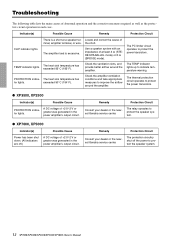
... short. Troubleshooting The following table lists the main causes of abnormal operation and the corrective measures required as well as the protective circuit operation in the power amplifier's output circuit. The PC limiter circuit operates to protect the speaker system. 12 XP7000/XP5000/XP3500/XP2500/XP1000 Owner's Manual The amplifier load is a short at least 4 Ω (STEREO/PARALLEL mode) or...
... short. Troubleshooting The following table lists the main causes of abnormal operation and the corrective measures required as well as the protective circuit operation in the power amplifier's output circuit. The PC limiter circuit operates to protect the speaker system. 12 XP7000/XP5000/XP3500/XP2500/XP1000 Owner's Manual The amplifier load is a short at least 4 Ω (STEREO/PARALLEL mode) or...
Owner's Manual
Page 14
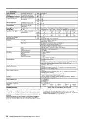
... wrench), Owner's Manual * These specifications apply to rated power supplies of 120V, 230V and 240V. 0 dBu=0.775 Vrms, Half Power=1/2 Output Power (3 dB below rated power) Specifications and descriptions in EN55103-1 and EN55103-2. max, Rated Power 8 Ω Switch Position Maximum Input Voltage Input Impedance Controls Front Panel Rear Panel Connectors Indicators Load Protection Input Output MONITOR/REMOTE POWER/STANDBY SIGNAL CLIP/LIMIT PROTECTION/TEMP Amplifier Protection Power Supply Protection Cooling Power Requirements Dimensions...
... wrench), Owner's Manual * These specifications apply to rated power supplies of 120V, 230V and 240V. 0 dBu=0.775 Vrms, Half Power=1/2 Output Power (3 dB below rated power) Specifications and descriptions in EN55103-1 and EN55103-2. max, Rated Power 8 Ω Switch Position Maximum Input Voltage Input Impedance Controls Front Panel Rear Panel Connectors Indicators Load Protection Input Output MONITOR/REMOTE POWER/STANDBY SIGNAL CLIP/LIMIT PROTECTION/TEMP Amplifier Protection Power Supply Protection Cooling Power Requirements Dimensions...
Owner's Manual
Page 15
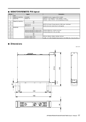
■ MONITOR/REMOTE PIN layout Pin No. 1 2 3 GND REMOTE CONTROL MONITOR Signal STANDBY MODEL ID 4 REMOTE CONTROL NC 5 NC 6 MUTE CH B 7 MUTE CH A 8 MONITOR NC 9 NC 10 PROTECTION/MUTE STATUS CH B 11 PROTECTION/MUTE STATUS CH A 12 NC 13 NC 14 OUTPUT LEVEL CH B 15 OUTPUT LEVEL CH A Description STANDBY Control: Supply 5 VDC, 5 mADC XP7000: 1.0 kΩ, XP5000: 1.2 kΩ, XP3500: 1.5 kΩ, XP2500: 1.8 kΩ, XP1000: 2.2 kΩ (Impedance to GND) MUTE On Control: Connect the pin to...
■ MONITOR/REMOTE PIN layout Pin No. 1 2 3 GND REMOTE CONTROL MONITOR Signal STANDBY MODEL ID 4 REMOTE CONTROL NC 5 NC 6 MUTE CH B 7 MUTE CH A 8 MONITOR NC 9 NC 10 PROTECTION/MUTE STATUS CH B 11 PROTECTION/MUTE STATUS CH A 12 NC 13 NC 14 OUTPUT LEVEL CH B 15 OUTPUT LEVEL CH A Description STANDBY Control: Supply 5 VDC, 5 mADC XP7000: 1.0 kΩ, XP5000: 1.2 kΩ, XP3500: 1.5 kΩ, XP2500: 1.8 kΩ, XP1000: 2.2 kΩ (Impedance to GND) MUTE On Control: Connect the pin to...
Owner's Manual
Page 16
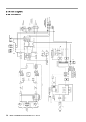
... B-1 - 5way DATA PORT (MONITOR/REMOTE) B OUTPUT LEVEL A OUTPUT LEVEL MUTE PROTECT STATUS STANDBY Model ID ■ Block Diagram ● XP7000/XP5000 16 XP7000/XP5000/XP3500/XP2500/XP1000 Owner's Manual CH A XLR 12 3 G INPUT [+22dBu MAX] - + G - + Euroblock CH B 12 3 XLR OFF HA BA HPF 20Hz 20Hz CH A ATT +4dBu +26dB +32dB HPF 55Hz 55Hz HPF 12dB/oct INV GAIN STEREO BRIDGE PARALLEL HA STEREO BRIDGE PARALLEL CH B ATT...
... B-1 - 5way DATA PORT (MONITOR/REMOTE) B OUTPUT LEVEL A OUTPUT LEVEL MUTE PROTECT STATUS STANDBY Model ID ■ Block Diagram ● XP7000/XP5000 16 XP7000/XP5000/XP3500/XP2500/XP1000 Owner's Manual CH A XLR 12 3 G INPUT [+22dBu MAX] - + G - + Euroblock CH B 12 3 XLR OFF HA BA HPF 20Hz 20Hz CH A ATT +4dBu +26dB +32dB HPF 55Hz 55Hz HPF 12dB/oct INV GAIN STEREO BRIDGE PARALLEL HA STEREO BRIDGE PARALLEL CH B ATT...
Owner's Manual
Page 17
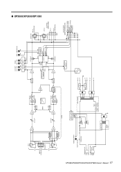
...DATA PORT (MONITOR/REMOTE) B OUTPUT LEVEL A OUTPUT LEVEL MUTE PROTECT STATUS STANDBY Model ID CH B-2 2+ SPEAKON OUTPUT (SPEAKERS) - ● XP3500/XP2500/XP1000 XP7000/XP5000/XP3500/XP2500/XP1000 Owner's Manual 17 CH A XLR 12 3 G INPUT - + [+22dBu MAX] G - + Euroblock CH B 12 3 XLR HA STEREO BRIDGE PARALLEL HA STEREO BRIDGE PARALLEL CH...SP RELAY MODE FAN CONTROL CIRCUIT POWER/STANDBY GR/OR (GR+RE) J destination only POWER SW Except J destination FG RELAY & LED DRIVE CIRCUIT PO SBY RELAY 1 RELAY 2 MAIN TRANS SUB TRANS 130˚C Thermal Thermal cutoff protector +24...
...DATA PORT (MONITOR/REMOTE) B OUTPUT LEVEL A OUTPUT LEVEL MUTE PROTECT STATUS STANDBY Model ID CH B-2 2+ SPEAKON OUTPUT (SPEAKERS) - ● XP3500/XP2500/XP1000 XP7000/XP5000/XP3500/XP2500/XP1000 Owner's Manual 17 CH A XLR 12 3 G INPUT - + [+22dBu MAX] G - + Euroblock CH B 12 3 XLR HA STEREO BRIDGE PARALLEL HA STEREO BRIDGE PARALLEL CH...SP RELAY MODE FAN CONTROL CIRCUIT POWER/STANDBY GR/OR (GR+RE) J destination only POWER SW Except J destination FG RELAY & LED DRIVE CIRCUIT PO SBY RELAY 1 RELAY 2 MAIN TRANS SUB TRANS 130˚C Thermal Thermal cutoff protector +24...
Owner's Manual
Page 18
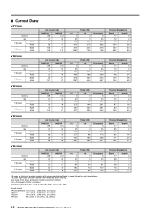
... 17 165 42 208 52 376 95 479 121 18 XP7000/XP5000/XP3500/XP2500/XP1000 Owner's Manual ■ Current Draw XP7000 standby idle 1/8 power 8Ω/ch 4Ω/ch 1/3 power 8Ω/ch 4Ω/ch Line Current (A) 100/120V ...standby idle 1/8 power 8Ω/ch 4Ω/ch 1/3 power 8Ω/ch 4Ω/ch Line Current (A) 100/120V 230/240V 0.08 0.04 1.0 0.5 1.1 0.6 1.2 0.7 2.4 1.3 2.9 1.6 In 5 20 76 91 184 220 Power (W) Out 0 0 28 30 73 80 Dissipated 5 20 48 61 110 140 1/8 power is typical of program material with extremely heavy clipping. Test signal...
... 17 165 42 208 52 376 95 479 121 18 XP7000/XP5000/XP3500/XP2500/XP1000 Owner's Manual ■ Current Draw XP7000 standby idle 1/8 power 8Ω/ch 4Ω/ch 1/3 power 8Ω/ch 4Ω/ch Line Current (A) 100/120V ...standby idle 1/8 power 8Ω/ch 4Ω/ch 1/3 power 8Ω/ch 4Ω/ch Line Current (A) 100/120V 230/240V 0.08 0.04 1.0 0.5 1.1 0.6 1.2 0.7 2.4 1.3 2.9 1.6 In 5 20 76 91 184 220 Power (W) Out 0 0 28 30 73 80 Dissipated 5 20 48 61 110 140 1/8 power is typical of program material with extremely heavy clipping. Test signal...
Owner's Manual
Page 19
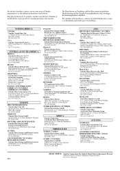
...-5111 COUNTRIES AND TRUST TERRITORIES IN PACIFIC OCEAN Yamaha Corporation, Asia-Pacific Music Marketing Group Nakazawa-cho 10-1, Naka-ku, Hamamatsu, Japan 430-8650 Tel: +81-53-460-2313 PA24 HEAD OFFICE Yamaha Corporation, Pro Audio & Digital Musical Instrument Division Nakazawa-cho 10-1, Naka-ku, ...Hamamatsu, Japan 430-8650 Tel: +81-53-460-2441 Para detalles sobre productos, contacte su tienda Yamaha más cercana o el distribuidor autorizado que se...
...-5111 COUNTRIES AND TRUST TERRITORIES IN PACIFIC OCEAN Yamaha Corporation, Asia-Pacific Music Marketing Group Nakazawa-cho 10-1, Naka-ku, Hamamatsu, Japan 430-8650 Tel: +81-53-460-2313 PA24 HEAD OFFICE Yamaha Corporation, Pro Audio & Digital Musical Instrument Division Nakazawa-cho 10-1, Naka-ku, ...Hamamatsu, Japan 430-8650 Tel: +81-53-460-2441 Para detalles sobre productos, contacte su tienda Yamaha más cercana o el distribuidor autorizado que se...


