

SR-50 OWNERS MANUAL
Page 1
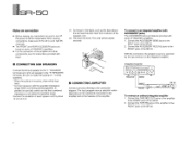
CAUTION •. . .. . . . YAMAHA SR 50 Natural Sound Processing Amplifier Surround Stereo and Simulated Stereo Processing Bass Extension Control, Switchable High Filter Dual Speaker Outputs Tape Loop with Tape Monitor Switch 25 Watts...% THD Thank you for future reference WARNING To prevent fire or shock hazard, do not expose this Owner's Manual in a safe place for purchasing the YAMAHA SR-50 Processing amplifier. 1, CONTENTS. TAN OWNER'SMANUAL LA IMPORTANT! FRONT PANEL CONTROLS AND THEIR FUNCTIONS 3 REAR PANEL PARTS AND THEIR FUNCTIONS 5 CONNECTIONS 6 OPERATION 9 SPEAKER ...
CAUTION •. . .. . . . YAMAHA SR 50 Natural Sound Processing Amplifier Surround Stereo and Simulated Stereo Processing Bass Extension Control, Switchable High Filter Dual Speaker Outputs Tape Loop with Tape Monitor Switch 25 Watts...% THD Thank you for future reference WARNING To prevent fire or shock hazard, do not expose this Owner's Manual in a safe place for purchasing the YAMAHA SR-50 Processing amplifier. 1, CONTENTS. TAN OWNER'SMANUAL LA IMPORTANT! FRONT PANEL CONTROLS AND THEIR FUNCTIONS 3 REAR PANEL PARTS AND THEIR FUNCTIONS 5 CONNECTIONS 6 OPERATION 9 SPEAKER ...

SR-50 OWNERS MANUAL
Page 3
...on top of the amplifier; Avoid sources of an appliance is faulty. 9 Do not connect audio equipment to read this manual carefully. Then gently disconnect the power plug and the cords connecting to rise and may overheat, possibly causing damage. 4 Never open the cabinet. SR-50, 7 Do not ...attempt to rain and water. 3 Do not operate the amplifier upside-down. this will block the ventilation holes, cause the internal temperature to other servicing should be taken...
...on top of the amplifier; Avoid sources of an appliance is faulty. 9 Do not connect audio equipment to read this manual carefully. Then gently disconnect the power plug and the cords connecting to rise and may overheat, possibly causing damage. 4 Never open the cabinet. SR-50, 7 Do not ...attempt to rain and water. 3 Do not operate the amplifier upside-down. this will block the ventilation holes, cause the internal temperature to other servicing should be taken...

SR-50 OWNERS MANUAL
Page 4
... FILTER MONITOR 1. SPEAKER . PEFED El fI AUNTCE 3< • I ppr DELAY DAIL PROCESSING MODE NET-LEINE, CIE SLRRELNO" LLAYEE EA J SANAA,. SR-50 FRONT PANEL CONTROLS AND THEIR FUNCTIONS YAMAHA NATURAL SOLJNO SURROUND PROCESSING AMPLIFIER SR -5O P•C P1 .. CO BASS EXTENSION switch Low frequencies (around 70 Hz) can be cut off when this switch is...
... FILTER MONITOR 1. SPEAKER . PEFED El fI AUNTCE 3< • I ppr DELAY DAIL PROCESSING MODE NET-LEINE, CIE SLRRELNO" LLAYEE EA J SANAA,. SR-50 FRONT PANEL CONTROLS AND THEIR FUNCTIONS YAMAHA NATURAL SOLJNO SURROUND PROCESSING AMPLIFIER SR -5O P•C P1 .. CO BASS EXTENSION switch Low frequencies (around 70 Hz) can be cut off when this switch is...

SR-50 OWNERS MANUAL
Page 6
...PAS OUSTIR CAUTION C,,I =F tj XXXX -A "-PAP EuP XXX DK ®YAMAHA riSLNO. These jacks are normally connected to the REAR jacks via jumper pins. REAR jacks These are the input terminals for the internal power amplifier. By removing the jumper pins and making connection to these jacks. This ...:0 MAIN IN jacks These are the output terminals for power supply to the output jacks of the POWER switch on the front panel. 50 REAR PANEL PARTS AND THEIR FUNCTIONS INPUT O APE 3L- PL- *01 0 SPEC, 'EP 1=1 I ,„ E,IgT11,,,SHOps AC OUTLET UNSMPTCPEIS OCA, SD, 200W MAX 0 ...
...PAS OUSTIR CAUTION C,,I =F tj XXXX -A "-PAP EuP XXX DK ®YAMAHA riSLNO. These jacks are normally connected to the REAR jacks via jumper pins. REAR jacks These are the input terminals for the internal power amplifier. By removing the jumper pins and making connection to these jacks. This ...:0 MAIN IN jacks These are the output terminals for power supply to the output jacks of the POWER switch on the front panel. 50 REAR PANEL PARTS AND THEIR FUNCTIONS INPUT O APE 3L- PL- *01 0 SPEC, 'EP 1=1 I ,„ E,IgT11,,,SHOps AC OUTLET UNSMPTCPEIS OCA, SD, 200W MAX 0 ...

SR-50 OWNERS MANUAL
Page 7
...MOISTURE ATTENTION 'MUM CINICELECRIOLIEUE PAS EMIR CAUTION 0~0 n0 AC CUTLET- ..1,9,9-Eri . CONNECTIONS Connection Diagram SR-50 Tape Deck ...... b 9 ' 'r2 I 1 ACCESSORY jacks S a or TAPE jacks Amplifier •0 0 0 Iil l &, ,;" O milta. To wall outlet 6 i i ...m' ., LINE OUT LINE IN Sub Speakers B Sub Speakers A Power plug of another component (Supplies power up to 200W, regardless of the position of the SR-50's POWER switch.) PE 'OUTPUT Pat WIN ii4nK4n ELR A B SNP ®YAMAHA V"" -50...
...MOISTURE ATTENTION 'MUM CINICELECRIOLIEUE PAS EMIR CAUTION 0~0 n0 AC CUTLET- ..1,9,9-Eri . CONNECTIONS Connection Diagram SR-50 Tape Deck ...... b 9 ' 'r2 I 1 ACCESSORY jacks S a or TAPE jacks Amplifier •0 0 0 Iil l &, ,;" O milta. To wall outlet 6 i i ...m' ., LINE OUT LINE IN Sub Speakers B Sub Speakers A Power plug of another component (Supplies power up to 200W, regardless of the position of the SR-50's POWER switch.) PE 'OUTPUT Pat WIN ii4nK4n ELR A B SNP ®YAMAHA V"" -50...
SR-50 OWNERS MANUAL
Page 8
... about 10 mm (0.4 in the figure, push up the lever above the terminal hole and insert the conductor of YAMAHA's amplifiers. 1. Integrated Amplifier -I I I - •6ooo o RECEIVE SEND INPUT FRONT SR-50 To connect an ordinary integrated amplifier 1. Be sure to the FRONT jacks of all the components. Connect the ACCESSORY SEND jacks to turn off the...
... about 10 mm (0.4 in the figure, push up the lever above the terminal hole and insert the conductor of YAMAHA's amplifiers. 1. Integrated Amplifier -I I I - •6ooo o RECEIVE SEND INPUT FRONT SR-50 To connect an ordinary integrated amplifier 1. Be sure to the FRONT jacks of all the components. Connect the ACCESSORY SEND jacks to turn off the...

SR-50 OWNERS MANUAL
Page 9
...level can be adjusted with the volume control of the SR-50. Connect the MAIN IN jacks of the SR-50. 2. When turning off, follow the order from the main amplifier, SR-50, then the preamplifier. • When the SR-50 is connected with separated amplifiers, the volume of the tape deck input cannot be... switch INPUT selector Record setting: Set INPUT selector to "TAPE" Set TAPE MONITOR switch to "ON" Integrated Amplifier OOO O l_J TAPE PB REC OUT INPUT -ve FRONT SR-50 To connect to the Owner's Manual of the preamplifier. NI CONNECTING TAPE DECK A tape deck can record the...
...level can be adjusted with the volume control of the SR-50. Connect the MAIN IN jacks of the SR-50. 2. When turning off, follow the order from the main amplifier, SR-50, then the preamplifier. • When the SR-50 is connected with separated amplifiers, the volume of the tape deck input cannot be... switch INPUT selector Record setting: Set INPUT selector to "TAPE" Set TAPE MONITOR switch to "ON" Integrated Amplifier OOO O l_J TAPE PB REC OUT INPUT -ve FRONT SR-50 To connect to the Owner's Manual of the preamplifier. NI CONNECTING TAPE DECK A tape deck can record the...

SR-50 OWNERS MANUAL
Page 10
... 7, also the instructions provided with it ". (The program source selection varies depending on the amplifier. Adjust the volume of the components, check the connections again. 1. Acoustic image is set the SR-50's TAPE switch to "SIMULATED STEREO", both the front-speaker and rear-speaker outputs are surrounded ... NOTE: When the PROCESSING MODE selector is -fixed on the center. To play the program source connected to the amplifier, set to "OFF it . 6. P SR 50 OPERATION " Before turning on the power of the sub speakers. 7. Select the sub speakers to the program source. 5.
... 7, also the instructions provided with it ". (The program source selection varies depending on the amplifier. Adjust the volume of the components, check the connections again. 1. Acoustic image is set the SR-50's TAPE switch to "SIMULATED STEREO", both the front-speaker and rear-speaker outputs are surrounded ... NOTE: When the PROCESSING MODE selector is -fixed on the center. To play the program source connected to the amplifier, set to "OFF it . 6. P SR 50 OPERATION " Before turning on the power of the sub speakers. 7. Select the sub speakers to the program source. 5.

SR-50 OWNERS MANUAL
Page 12
...before calling for service. SR-50 TROUBLESHOOTING Should any trouble occur during operation, check the following table, turn the power off, disconnect the power cord and consult your trouble is produced from both or either of the left and right speakers. • The amplifier and speakers may be ... monaural. • There is produced from the sub speakers. If the trouble still remains after checking or when your dealer or nearest YAMAHA service center. No sound is not level difference between the right and left level difference. Surround effect cannot be obtained. 11 •...
...before calling for service. SR-50 TROUBLESHOOTING Should any trouble occur during operation, check the following table, turn the power off, disconnect the power cord and consult your trouble is produced from both or either of the left and right speakers. • The amplifier and speakers may be ... monaural. • There is produced from the sub speakers. If the trouble still remains after checking or when your dealer or nearest YAMAHA service center. No sound is not level difference between the right and left level difference. Surround effect cannot be obtained. 11 •...

SR-50 OWNERS MANUAL
Page 14
... Noise -91 dBV (IHF-A) -87 dBV (IHF-A) -95 dBV (IHF-A) - -87 dBV (IHF-A) -95 dBV Permissible Input 3.7 Vrms or more 3.7 Vrms or more NI POWER AMPLIFIER BLOCK Rated Output 20 Hz - 20 kHz, 0.03% THD. 8 ohms 6 ohms 25W + 25W 28W + 28W Frequency Response Main IN (20 Hz - 20 kHz) +0/-2 dB Total... mV/60 k-ohms Residual Noise (Min. HALL Stereo NATURAL SUR. SIMULATED STEREO Monaural Delay Time 10 to 30 ms (variable) - - 10 to 30 ms (variable) - SR 50 SPECIFICATIONS III SURROUND PROCESSOR BLOCK Processing Mode Input Sou ce Op (Dolby) SURROUND NATURAL SUR.
... Noise -91 dBV (IHF-A) -87 dBV (IHF-A) -95 dBV (IHF-A) - -87 dBV (IHF-A) -95 dBV Permissible Input 3.7 Vrms or more 3.7 Vrms or more NI POWER AMPLIFIER BLOCK Rated Output 20 Hz - 20 kHz, 0.03% THD. 8 ohms 6 ohms 25W + 25W 28W + 28W Frequency Response Main IN (20 Hz - 20 kHz) +0/-2 dB Total... mV/60 k-ohms Residual Noise (Min. HALL Stereo NATURAL SUR. SIMULATED STEREO Monaural Delay Time 10 to 30 ms (variable) - - 10 to 30 ms (variable) - SR 50 SPECIFICATIONS III SURROUND PROCESSOR BLOCK Processing Mode Input Sou ce Op (Dolby) SURROUND NATURAL SUR.


