

Owner's Manual
Page 4
...wonders of surround-sound encoded video sources available in a safe place for later reference. The DSP system takes full advantage of Yamaha's undisputed leadership in the field of digital audio processing to the business of setting up your system, and the DSP system will...Logic Surround Decoder, Dolby Digital Decoder and DTS Decoder. In addition, you a whole new world of a Yamaha Digital Sound Field Processing (DSP) System-an extremely sophisticated audio component. Congratulations! Please read this manual carefully when setting up the system and trying out its many capabilities.
...wonders of surround-sound encoded video sources available in a safe place for later reference. The DSP system takes full advantage of Yamaha's undisputed leadership in the field of digital audio processing to the business of setting up your system, and the DSP system will...Logic Surround Decoder, Dolby Digital Decoder and DTS Decoder. In addition, you a whole new world of a Yamaha Digital Sound Field Processing (DSP) System-an extremely sophisticated audio component. Congratulations! Please read this manual carefully when setting up the system and trying out its many capabilities.

Owner's Manual
Page 18
... of signals. Audio/video source equipment q Use RCA type pin plug cables for each of YAMAHA audio/video units numbered as 1, 3, 4, etc. q The output (or input) terminals of your components. FM ANT GND AM ANT GND EXTERNAL DECODER INPUT MAIN CENTER SURROUND CD OPTICAL DVD/LD... the ground wire disconnected. 14 TV/Satellite tuner Video cassette recorder : Indicates the direction of this unit and other components after all connections are completed. PREPARATION Connections Caution: Plug in some cases better results may be obtained with the exception described later.
... of signals. Audio/video source equipment q Use RCA type pin plug cables for each of YAMAHA audio/video units numbered as 1, 3, 4, etc. q The output (or input) terminals of your components. FM ANT GND AM ANT GND EXTERNAL DECODER INPUT MAIN CENTER SURROUND CD OPTICAL DVD/LD... the ground wire disconnected. 14 TV/Satellite tuner Video cassette recorder : Indicates the direction of this unit and other components after all connections are completed. PREPARATION Connections Caution: Plug in some cases better results may be obtained with the exception described later.

Owner's Manual
Page 19
...models only) REMOTE CONTROL (IN, OUT) terminals These terminals are used for use with the system remote control. In this way, up to the components for details about the S VIDEO terminal.) PREPARATION PAL/NTSC switch (China and General models only) GND Ω UNBAL. model) GND EXTERNAL DECODER ... COAXIAL OPTICAL DIGITAL SIGNAL S VIDEO VIDEO ON SCREEN SELECTOR IN OUT REMOTE CONTROL SUB WOOFER 15 When this unit is connected to 6 components can also operate it with the NTSC and PAL television formats. EXTERNAL DECO MAIN CENTER CD OPTICAL DVD/LD DVD/LD TV/DBS COAXIAL...
...models only) REMOTE CONTROL (IN, OUT) terminals These terminals are used for use with the system remote control. In this way, up to the components for details about the S VIDEO terminal.) PREPARATION PAL/NTSC switch (China and General models only) GND Ω UNBAL. model) GND EXTERNAL DECODER ... COAXIAL OPTICAL DIGITAL SIGNAL S VIDEO VIDEO ON SCREEN SELECTOR IN OUT REMOTE CONTROL SUB WOOFER 15 When this unit is connected to 6 components can also operate it with the NTSC and PAL television formats. EXTERNAL DECO MAIN CENTER CD OPTICAL DVD/LD DVD/LD TV/DBS COAXIAL...
Owner's Manual
Page 29
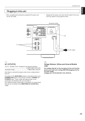
The maximum power (total power consumption of components) that can be connected to the SWITCHED AC OUTLET(S) is controlled by this unit's STANDBY/ON switch or the remote controller's POWER and STANDBY keys. ... this unit is not to any connected unit whenever this unit is turned on the rear panel of this unit must be used for your components to connect the power cords of time. These outlets will supply power to be set for a long period of your local main voltage BEFORE plugging...
The maximum power (total power consumption of components) that can be connected to the SWITCHED AC OUTLET(S) is controlled by this unit's STANDBY/ON switch or the remote controller's POWER and STANDBY keys. ... this unit is not to any connected unit whenever this unit is turned on the rear panel of this unit must be used for your components to connect the power cords of time. These outlets will supply power to be set for a long period of your local main voltage BEFORE plugging...

Owner's Manual
Page 65
...67 for details. 61 Notes ● You can be selected directly. Refer to control Yamaha tape decks. Components which can program the remote controller with the codes for the component that you do not use an LD player. Normally set to control by programming the ...remote controller with the codes for other manufacturers' audio and video components by turning the selector dial. Basic operation 1 Select the position for other Yamaha audio and video components with remote control capability, this remote controller can also enter the code for your...
...67 for details. 61 Notes ● You can be selected directly. Refer to control Yamaha tape decks. Components which can program the remote controller with the codes for the component that you do not use an LD player. Normally set to control by programming the ...remote controller with the codes for other manufacturers' audio and video components by turning the selector dial. Basic operation 1 Select the position for other Yamaha audio and video components with remote control capability, this remote controller can also enter the code for your...
Owner's Manual
Page 68
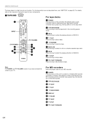
... the MD recorder. 2 REC/PAUSE 3 SKIP 4 PLAY 5 BACKWARD 6 DISPLAY 8 PAUSE 9 SKIP 0 STOP A FAST FORWARD 64 For MD recorders Enter the proper code for a Yamaha MD recorder is used. For the keys which are not described here, see "AMP/TUN" on page 62. For details, refer to the instruction manual... deck. 9 DIR B Press this key to select the playing direction of your MD recorder. 1 POWER This key turns on this unit if a code for your components. Ⅵ TAPE/MD TAPE/MD 1 POWER STANDBY TAPE/MD INPUT (TV POWER) 2 3 4 5 /DTS SURROUND CD 1 MONO MOVIE DVD/LD 4 ROCK PHONO 7 ...
... the MD recorder. 2 REC/PAUSE 3 SKIP 4 PLAY 5 BACKWARD 6 DISPLAY 8 PAUSE 9 SKIP 0 STOP A FAST FORWARD 64 For MD recorders Enter the proper code for a Yamaha MD recorder is used. For the keys which are not described here, see "AMP/TUN" on page 62. For details, refer to the instruction manual... deck. 9 DIR B Press this key to select the playing direction of your MD recorder. 1 POWER This key turns on this unit if a code for your components. Ⅵ TAPE/MD TAPE/MD 1 POWER STANDBY TAPE/MD INPUT (TV POWER) 2 3 4 5 /DTS SURROUND CD 1 MONO MOVIE DVD/LD 4 ROCK PHONO 7 ...

Owner's Manual
Page 69
... CD 1 MONO MOVIE DVD/LD 4 ROCK PHONO 7 HALL EXT. For an CD player: This key turns on this key to the instruction manual for your components. Ⅵ CD CD 1 POWER STANDBY CD INPUT 2 (TV POWER) 3 4 5 /DTS SURROUND CD 1 MONO MOVIE DVD/LD 4 ROCK PHONO 7 HALL EXT. This key functions... as PAUSE/STOP for a Yamaha LD player is used . DEC. 0 MOVIE THEATER 1 TUNER 2 TV SPORTS TV/DBS 5 JAZZ CLUB V-AUX 8 +10 ENTER MOVIE THEATER 2 TAPE/MD 3 DISCO VCR 6 CHURCH 9...
... CD 1 MONO MOVIE DVD/LD 4 ROCK PHONO 7 HALL EXT. For an CD player: This key turns on this key to the instruction manual for your components. Ⅵ CD CD 1 POWER STANDBY CD INPUT 2 (TV POWER) 3 4 5 /DTS SURROUND CD 1 MONO MOVIE DVD/LD 4 ROCK PHONO 7 HALL EXT. This key functions... as PAUSE/STOP for a Yamaha LD player is used . DEC. 0 MOVIE THEATER 1 TUNER 2 TV SPORTS TV/DBS 5 JAZZ CLUB V-AUX 8 +10 ENTER MOVIE THEATER 2 TAPE/MD 3 DISCO VCR 6 CHURCH 9...

Owner's Manual
Page 70
... MENU SET MENU TV EFFECT ON/OFF TV VOLUME DISPLAY TV INPUT (VCR) (*1) Press this key twice to the instruction manual for each of your components. Ⅵ VCR VCR Ⅵ TV TV Note TV POWER, TV VOLUME and TV INPUT function if you have entered the code for your TV. DEC...
... MENU SET MENU TV EFFECT ON/OFF TV VOLUME DISPLAY TV INPUT (VCR) (*1) Press this key twice to the instruction manual for each of your components. Ⅵ VCR VCR Ⅵ TV TV Note TV POWER, TV VOLUME and TV INPUT function if you have entered the code for your TV. DEC...

Owner's Manual
Page 71
...selector dial. REMOTE CONTROLLER English Entering manufacturer codes If you have a component which is not a Yamaha model, you can control the component with the remote controller to check the code entering is successful. Notes ● Some Yamaha CD players and tape decks cannot be controlled, enter another code ...for your component in the corresponding position of the VOLUME and keys at the same time and hold them to...
...selector dial. REMOTE CONTROLLER English Entering manufacturer codes If you have a component which is not a Yamaha model, you can control the component with the remote controller to check the code entering is successful. Notes ● Some Yamaha CD players and tape decks cannot be controlled, enter another code ...for your component in the corresponding position of the VOLUME and keys at the same time and hold them to...

Owner's Manual
Page 72
... DBS tuner VCR DVD player CD player Tape deck Code 0047 2566 3060 4545 YAMAHA 6187 YAMAHA 8524 YAMAHA Position TV CBL/DBS VCR DVD/LD CD TAPE/MD Component TV DBS tuner VCR DVD player CD player Tape deck We recommend that you want to the position for the all code numbers you.../MD 2 Press both of the VOLUME and keys at the same time and hold them until the indicator flashes twice. Code 0037 2455 3072 4545 YAMAHA 6187 YAMAHA 8524 YAMAHA 68
... DBS tuner VCR DVD player CD player Tape deck Code 0047 2566 3060 4545 YAMAHA 6187 YAMAHA 8524 YAMAHA Position TV CBL/DBS VCR DVD/LD CD TAPE/MD Component TV DBS tuner VCR DVD player CD player Tape deck We recommend that you want to the position for the all code numbers you.../MD 2 Press both of the VOLUME and keys at the same time and hold them until the indicator flashes twice. Code 0037 2455 3072 4545 YAMAHA 6187 YAMAHA 8524 YAMAHA 68

Owner's Manual
Page 73
...The protection circuit has been activated because of source is selected when the input signal of short circuit etc. The function "4. The component connected to the GND terminal. Play a source whose signals this unit into the standby mode suddenly soon after the power is turned ... Speaker connections are input to No. 10 is 2-channel stereo (analog/PCM). Incorrect cord connections. Output mode selection for your authorized YAMAHA dealer or service center. Select the appropriate input source with Dolby Digital or DTS do not have passed, connect the power and operate ...
...The protection circuit has been activated because of source is selected when the input signal of short circuit etc. The function "4. The component connected to the GND terminal. Play a source whose signals this unit into the standby mode suddenly soon after the power is turned ... Speaker connections are input to No. 10 is 2-channel stereo (analog/PCM). Incorrect cord connections. Output mode selection for your authorized YAMAHA dealer or service center. Select the appropriate input source with Dolby Digital or DTS do not have passed, connect the power and operate ...

Owner's Manual
Page 74
... minute. This unit is not possible to record the sound field on a tape deck connected to the "ON" position. This unit or another component cannot be recorded by an external electric shock (lightning, excessive static electricity, etc.) or power supply with low voltage. Direct sunlight or lighting (...be changed. The internal microcomputer has been frozen by a tape deck or VCR connected to the remote controller. The code for controlling the component in the SET MENU mode is not preset to this unit. Turn the power to this unit cannot be recorded. MEMORY GUARD" in the...
... minute. This unit is not possible to record the sound field on a tape deck connected to the "ON" position. This unit or another component cannot be recorded by an external electric shock (lightning, excessive static electricity, etc.) or power supply with low voltage. Direct sunlight or lighting (...be changed. The internal microcomputer has been frozen by a tape deck or VCR connected to the remote controller. The code for controlling the component in the SET MENU mode is not preset to this unit. Turn the power to this unit cannot be recorded. MEMORY GUARD" in the...


