Owners Manual
Page 2
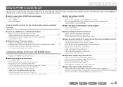
CONTENTS INTRODUCTION Features and capabilities 4 Using the TV OSD to operate the unit 5 View or modify content for the current input source
CONTENTS INTRODUCTION Features and capabilities 4 Using the TV OSD to operate the unit 5 View or modify content for the current input source
Owners Manual
Page 3
... SCENE function (SCENE menu 76 Editing a scene 76 SCENE menu 77 Setting sound program parameters (Sound Program menu 78 Editing sound programs 78 CINEMA DSP parameters 79 Parameters usable in certain sound programs 81 Parameters usable in surround decoder 82 Setting various functions (Setup menu ...99 Displaying/Setting the Advanced Setup menu 99 Setting the impedance of speakers 99 Avoiding crossing remote control signals when using multiple Yamaha receivers 100 Resetting the SIRIUS Satellite Radio™ parental lock code 100 Changing TV format 101 Removing HDMI video output up-...
... SCENE function (SCENE menu 76 Editing a scene 76 SCENE menu 77 Setting sound program parameters (Sound Program menu 78 Editing sound programs 78 CINEMA DSP parameters 79 Parameters usable in certain sound programs 81 Parameters usable in surround decoder 82 Setting various functions (Setup menu ...99 Displaying/Setting the Advanced Setup menu 99 Setting the impedance of speakers 99 Avoiding crossing remote control signals when using multiple Yamaha receivers 100 Resetting the SIRIUS Satellite Radio™ parental lock code 100 Changing TV format 101 Removing HDMI video output up-...
Owners Manual
Page 4
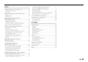
...quality playback using bi-amplification connections 18 ■ Automatic settings for each input source Speaker impedance configuration...18 - Speaker channels and functions ...13 - Yamaha Parametric Room Acoustic Optimizer 33 ■ External component connection (max. 16 inputs) and playback - to 7.1-channel configurations - Protective cover for 2- ... ■ 6 HDMI input jacks (5 + 1 VIDEO AUX) supporting Audio Return Channel and 3D video signal ■ 1-button input/sound program switching (SCENE function 41 ■ Speaker connections for front panel jacks ...7 -
...quality playback using bi-amplification connections 18 ■ Automatic settings for each input source Speaker impedance configuration...18 - Speaker channels and functions ...13 - Yamaha Parametric Room Acoustic Optimizer 33 ■ External component connection (max. 16 inputs) and playback - to 7.1-channel configurations - Protective cover for 2- ... ■ 6 HDMI input jacks (5 + 1 VIDEO AUX) supporting Audio Return Channel and 3D video signal ■ 1-button input/sound program switching (SCENE function 41 ■ Speaker connections for front panel jacks ...7 -
Owners Manual
Page 5
... The OSD is designed to operate the unit INTRODUCTION This unit features a sophisticated on the station/channel currently received 56, 63 - Select a sound program...48 View or modify content for selection 57, 64 - Select an input source ...47 - Display information on -screen display (OSD) ...operations such as the Content window that simplifies operations. Display the list of current input sources. ■ Select an input source, SCENE and sound program - The OSD mainly displays the ON SCREEN and OPTION menus, as well as play, stop and pause using the Utility ...56, 63...
... The OSD is designed to operate the unit INTRODUCTION This unit features a sophisticated on the station/channel currently received 56, 63 - Select a sound program...48 View or modify content for selection 57, 64 - Select an input source ...47 - Display information on -screen display (OSD) ...operations such as the Content window that simplifies operations. Display the list of current input sources. ■ Select an input source, SCENE and sound program - The OSD mainly displays the ON SCREEN and OPTION menus, as well as play, stop and pause using the Utility ...56, 63...
Owners Manual
Page 8
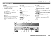
... (☞p. 56) or a SIRIUS preset channel (☞p. 61). j Front panel display Displays information on and standby (☞p. 106). q PROGRAM l / h Selects a sound program (☞p. 41). t VOLUME Adjusts the volume level. This indicator also lights up in any of speakers/headphones (☞p. 40). n INPUT l / h Selects an ...unit is in standby mode. • When the Standby Through function is enabled and audio/video from which is placed in the Yamaha iPod universal dock, is charging while the unit is in order. ZONE2 ZONE CONTROL INFO MEMORY PRESET CATEGORY FM AM INPUT BD ...
... (☞p. 56) or a SIRIUS preset channel (☞p. 61). j Front panel display Displays information on and standby (☞p. 106). q PROGRAM l / h Selects a sound program (☞p. 41). t VOLUME Adjusts the volume level. This indicator also lights up in any of speakers/headphones (☞p. 40). n INPUT l / h Selects an ...unit is in standby mode. • When the Standby Through function is enabled and audio/video from which is placed in the Yamaha iPod universal dock, is charging while the unit is in order. ZONE2 ZONE CONTROL INFO MEMORY PRESET CATEGORY FM AM INPUT BD ...

Owners Manual
Page 9
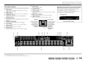
...58). INTRODUCTION Part names and functions l AUDIO1-2 jacks For connecting external components equipped with component video signals, using three cables to input sound into this unit (☞p. 28). Use these jacks to output audio/video signals to an AC wall outlet. TRIGGER OUT CENTER SPEAKERS ... HDMI 2 REMOTE IN HDMI 3 FRONT OUT 75 PB VIDEO Y MONITOR OUT +12V 0.1A MAX. Rear panel a DOCK jack For connecting an optional Yamaha iPod universal dock (such as the AV5-6 or AUDIO1-2 are selected (☞p. 31). c ANTENNA jacks For connecting AM and FM antennas (☞p. 32...
...58). INTRODUCTION Part names and functions l AUDIO1-2 jacks For connecting external components equipped with component video signals, using three cables to input sound into this unit (☞p. 28). Use these jacks to output audio/video signals to an AC wall outlet. TRIGGER OUT CENTER SPEAKERS ... HDMI 2 REMOTE IN HDMI 3 FRONT OUT 75 PB VIDEO Y MONITOR OUT +12V 0.1A MAX. Rear panel a DOCK jack For connecting an optional Yamaha iPod universal dock (such as the AV5-6 or AUDIO1-2 are selected (☞p. 31). c ANTENNA jacks For connecting AM and FM antennas (☞p. 32...
Owners Manual
Page 10
...k m J 1 : "SB" is muted. b SIRIUS indicator Lights up when the sleep timer is on (☞p. 44). SW L CR SL SR SBL SBR Sound program (DSP program) ab c de f g hi j SIRIUS ENHANCER STEREO 3 TUNED SLEEP ZONE 2 VOL. g SLEEP indicator Lights up when a SiriusConnect tuner is ...fINFO repeatedly to the status of information on the remote control are available for operations. Front panel display a HDMI indicator Lights up when a sound field effect that uses CINEMA DSP technology is selected. J 2 : During FM/AM reception, the frequency is turned on (☞p. 11...
...k m J 1 : "SB" is muted. b SIRIUS indicator Lights up when the sleep timer is on (☞p. 44). SW L CR SL SR SBL SBR Sound program (DSP program) ab c de f g hi j SIRIUS ENHANCER STEREO 3 TUNED SLEEP ZONE 2 VOL. g SLEEP indicator Lights up when a SiriusConnect tuner is ...fINFO repeatedly to the status of information on the remote control are available for operations. Front panel display a HDMI indicator Lights up when a sound field effect that uses CINEMA DSP technology is selected. J 2 : During FM/AM reception, the frequency is turned on (☞p. 11...
Owners Manual
Page 11
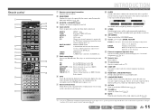
...set the time for external component operations (☞p. 97). J1 MULTI CH INPUT MULTI CH INPUT jacks DOCK A Yamaha iPod universal dock, iPod wireless receiver, or Bluetooth wireless audio receiver TUNER connected to FM. These keys are using...;p. 96). p RECEIVER A (RECEIVER Power) Switches this unit to operate this key glows orange. INTRODUCTION Part names and functions h SLEEP Switches this unit between the sound field effect (sound program) you want to AM. Remote control a b c d e f g h i j MAIN ZONE 2 CODE SET SOURCE RECEIVER HDMI 1 2 3 4 AUDIO 5 ...
...set the time for external component operations (☞p. 97). J1 MULTI CH INPUT MULTI CH INPUT jacks DOCK A Yamaha iPod universal dock, iPod wireless receiver, or Bluetooth wireless audio receiver TUNER connected to FM. These keys are using...;p. 96). p RECEIVER A (RECEIVER Power) Switches this unit to operate this key glows orange. INTRODUCTION Part names and functions h SLEEP Switches this unit between the sound field effect (sound program) you want to AM. Remote control a b c d e f g h i j MAIN ZONE 2 CODE SET SOURCE RECEIVER HDMI 1 2 3 4 AUDIO 5 ...

Owners Manual
Page 13
... is used with 6.1/ 7.1-channel (including surround back channel), sound for bass sounds and low-frequency effect (LFE) sounds included in Dolby Digital and DTS. When used for the front channel sounds (stereo sound) and effect sounds. ■ Surround left and right speakers facing slightly inward to... left and right sides facing the listening position. The same separation as with a richer and more spatial presence is for effect and vocal sounds with 6.1ch sound, arrange these speakers at a height of 4.9 - 5.9 ft. (1.5 - 1.8 m) from the ideal listening position in the front of...
... is used with 6.1/ 7.1-channel (including surround back channel), sound for bass sounds and low-frequency effect (LFE) sounds included in Dolby Digital and DTS. When used for the front channel sounds (stereo sound) and effect sounds. ■ Surround left and right speakers facing slightly inward to... left and right sides facing the listening position. The same separation as with a richer and more spatial presence is for effect and vocal sounds with 6.1ch sound, arrange these speakers at a height of 4.9 - 5.9 ft. (1.5 - 1.8 m) from the ideal listening position in the front of...

Owners Manual
Page 14
...to this unit according to the speaker configuration. Power Amp Assign 7ch Normal (Default) ■ Adding the presence speakers for a richer sound field effect ■ Presence speaker layout (7 speakers + subwoofer + presence speakers) Front speaker R Front speaker L Presence speaker L ... cm) or more Surround back speaker R This unit automatically selects the presence speakers or surround back speakers to output sounds according to the selected sound program. Speaker jacks EXTRA SP jack FRONT L/R, CENTER, SURROUND L/R, SURROUND BACK L/R, SUBWOOFER Presence L/R speakers ■...
...to this unit according to the speaker configuration. Power Amp Assign 7ch Normal (Default) ■ Adding the presence speakers for a richer sound field effect ■ Presence speaker layout (7 speakers + subwoofer + presence speakers) Front speaker R Front speaker L Presence speaker L ... cm) or more Surround back speaker R This unit automatically selects the presence speakers or surround back speakers to output sounds according to the selected sound program. Speaker jacks EXTRA SP jack FRONT L/R, CENTER, SURROUND L/R, SURROUND BACK L/R, SUBWOOFER Presence L/R speakers ■...

Owners Manual
Page 15
... speaker R Front speaker L Subwoofer Surround speaker R Center speaker Surround speaker L This unit can mix 7.1-channel audio source down to 5.1-channel sound. Speaker jacks EXTRA SP jack FRONT L/R, CENTER, SURROUND L/R, SURROUND BACK L/R, SUBWOOFER No used ■ Assigning a speaker configuration A speaker ... Connect the speakers to the following jacks according to the speaker layout. Refer to the speaker layout. amp connections for a high quality sound ■ 5-channel speaker layout (Front speakers (Bi-amp) + 3 speakers) Front speaker L (Bi-amp connection) Front speaker R...
... speaker R Front speaker L Subwoofer Surround speaker R Center speaker Surround speaker L This unit can mix 7.1-channel audio source down to 5.1-channel sound. Speaker jacks EXTRA SP jack FRONT L/R, CENTER, SURROUND L/R, SURROUND BACK L/R, SUBWOOFER No used ■ Assigning a speaker configuration A speaker ... Connect the speakers to the following jacks according to the speaker layout. Refer to the speaker layout. amp connections for a high quality sound ■ 5-channel speaker layout (Front speakers (Bi-amp) + 3 speakers) Front speaker L (Bi-amp connection) Front speaker R...

Owners Manual
Page 16
... the speaker layout. CONNECTIONS Connecting speakers En 16 Power Amp Assign 7ch + 1ZONE Front speaker L Front speaker R J 1 : Sound cannot be controlled. When the built-in amplifier for details on , the speakers that output the sound are switched from both the surround back speakers and the speakers in another room automatically. ■ Using...
... the speaker layout. CONNECTIONS Connecting speakers En 16 Power Amp Assign 7ch + 1ZONE Front speaker L Front speaker R J 1 : Sound cannot be controlled. When the built-in amplifier for details on , the speakers that output the sound are switched from both the surround back speakers and the speakers in another room automatically. ■ Using...
Owners Manual
Page 17
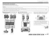
...display when this unit and the speakers, and the other cable into the "-" (negative, black) terminal. • Be careful that output front effect sounds can be connected to the next page En 17 If the speaker cables short circuit, "CHECK SP WIRES!" will appear on this unit is a ...at the same time. Presence speaker R Presence speaker L The presence speakers (PL/PR) that the core of this unit. With the sound programs (☞p. 45), sound with the metal areas of the speaker cable does not touch anything or come into contact with a richer and more spatial presence can be...
...display when this unit and the speakers, and the other cable into the "-" (negative, black) terminal. • Be careful that output front effect sounds can be connected to the next page En 17 If the speaker cables short circuit, "CHECK SP WIRES!" will appear on this unit is a ...at the same time. Presence speaker R Presence speaker L The presence speakers (PL/PR) that the core of this unit. With the sound programs (☞p. 45), sound with the metal areas of the speaker cable does not touch anything or come into contact with a richer and more spatial presence can be...

Owners Manual
Page 21
... cables, connecting the red plug to the red R jack, and the white plug to connect. ■ Audio/Video jacks HDMI jacks Digital video and digital sound are transmitted through a single jack. Connecting external components Cable plugs and jacks This unit is equipped with three plugs. Use fiber-optic cables for optical...
... cables, connecting the red plug to the red R jack, and the white plug to connect. ■ Audio/Video jacks HDMI jacks Digital video and digital sound are transmitted through a single jack. Connecting external components Cable plugs and jacks This unit is equipped with three plugs. Use fiber-optic cables for optical...
Owners Manual
Page 24
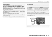
...input source to AV4 with just a single key operation using the SCENE function (☞p. 41). CONNECTIONS Connecting external components When using other TVs To transmit sound from the TV to this unit, connect AV1-6 or AUDIO1-2 jacks to the COAXIAL jack of the AV2 or AV3 with a stereo pin cable. Connecting... TV's audio output jack to one of the AV1 or AV4 with Audio Return Channel function" (☞p. 104). Connect to enjoy the TV sound. ■ Listening to TV audio To transmit sound from the TV to this unit, connect as followings according to the TV: When using a TV that makes TV...
...input source to AV4 with just a single key operation using the SCENE function (☞p. 41). CONNECTIONS Connecting external components When using other TVs To transmit sound from the TV to this unit, connect AV1-6 or AUDIO1-2 jacks to the COAXIAL jack of the AV2 or AV3 with a stereo pin cable. Connecting... TV's audio output jack to one of the AV1 or AV4 with Audio Return Channel function" (☞p. 104). Connect to enjoy the TV sound. ■ Listening to TV audio To transmit sound from the TV to this unit, connect as followings according to the TV: When using a TV that makes TV...

Owners Manual
Page 29
... a multi-format player or an external decoder This unit has 8 sets of your playback component, such as the input source, the digital sound field processor and tone control are performed between the HDMI compatible device and this unit, only the HDMI signal will be displayed on the front... panel to temporarily connect devices such as a game console to 7.1channel multi-channel sound. CONNECTIONS Connecting external components • Be sure to turn down the volume when connecting this unit and the other devices. • When both...
... a multi-format player or an external decoder This unit has 8 sets of your playback component, such as the input source, the digital sound field processor and tone control are performed between the HDMI compatible device and this unit, only the HDMI signal will be displayed on the front... panel to temporarily connect devices such as a game console to 7.1channel multi-channel sound. CONNECTIONS Connecting external components • Be sure to turn down the volume when connecting this unit and the other devices. • When both...
Owners Manual
Page 30
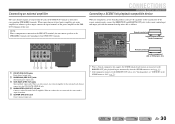
...1 SUBWOOFER 2 EXTRA SP ZONE2/ PRESENCE CONNECTIONS Connecting external components Connecting a SCENE link playback-compatible device When the components are the Yamaha products and have the capability of the transmission of the remote control signals, connect the REMOTE IN and REMOTE OUT jacks to "Off...SURROUND SUR.BACK SUBWOOFER MULTI CH INPUT AUDIO OUT Remote control out Infrared signal receiver or Yamaha component Remote control in amplifier. When two subwoofers are connected, the same sound is connected to the PRE OUT terminals, do not connect speakers to the SPEAKERS terminals ...
...1 SUBWOOFER 2 EXTRA SP ZONE2/ PRESENCE CONNECTIONS Connecting external components Connecting a SCENE link playback-compatible device When the components are the Yamaha products and have the capability of the transmission of the remote control signals, connect the REMOTE IN and REMOTE OUT jacks to "Off...SURROUND SUR.BACK SUBWOOFER MULTI CH INPUT AUDIO OUT Remote control out Infrared signal receiver or Yamaha component Remote control in amplifier. When two subwoofers are connected, the same sound is connected to the PRE OUT terminals, do not connect speakers to the SPEAKERS terminals ...

Owners Manual
Page 33
...which this unit on . • The video input to maximum. Refrain from using a tripod, use the tripod screws to provide an optimal sound field. This unit • The headphones are installed, first use equipment that the test tone does not frighten small children. TV • This...is turned on the front panel display or TV screen. 1 Check the following when using YPAO. • The test tone is equipped with a Yamaha Parametric Room Acoustic Optimizer (YPAO) that adjusts the status, size, and volume balance of the YPAO microphone upwards. Subwoofer • The power is...
...which this unit on . • The video input to maximum. Refrain from using a tripod, use the tripod screws to provide an optimal sound field. This unit • The headphones are installed, first use equipment that the test tone does not frighten small children. TV • This...is turned on the front panel display or TV screen. 1 Check the following when using YPAO. • The test tone is equipped with a Yamaha Parametric Room Acoustic Optimizer (YPAO) that adjusts the status, size, and volume balance of the YPAO microphone upwards. Subwoofer • The power is...

Owners Manual
Page 36
... be reloaded if you are cleared. NOTE When automatic setup parameters are reloaded, manually configured settings are not satisfied with manually configured speaker setup and sound adjustments. b a c CONNECTIONS Setting up the speaker parameters automatically (YPAO) 2 Select the desired menu item (or enable a function) using kCursor B / C / D / E and kENTER. 3 Press kRETURN to this...
... be reloaded if you are cleared. NOTE When automatic setup parameters are reloaded, manually configured settings are not satisfied with manually configured speaker setup and sound adjustments. b a c CONNECTIONS Setting up the speaker parameters automatically (YPAO) 2 Select the desired menu item (or enable a function) using kCursor B / C / D / E and kENTER. 3 Press kRETURN to this...

Owners Manual
Page 37
... is displayed after measurement See "Warning messages" (☞p. 39) for instructions on the unit and use YPAO again. ■ When a warning message is displayed, optimal sound will not be confirmed from the TV screen display. k When "E-1," "E-2," "E-3," "E-4" or "E-6" is displayed during measurement See "Error messages" (☞p. 38) for accurate measurement. When "E-5," "E-7," "E-8" or...
... is displayed after measurement See "Warning messages" (☞p. 39) for instructions on the unit and use YPAO again. ■ When a warning message is displayed, optimal sound will not be confirmed from the TV screen display. k When "E-1," "E-2," "E-3," "E-4" or "E-6" is displayed during measurement See "Error messages" (☞p. 38) for accurate measurement. When "E-5," "E-7," "E-8" or...


