
Owners Manual
Page 1
AV Receiver Owner's Manual English for U.S.A.
AV Receiver Owner's Manual English for U.S.A.
Owners Manual
Page 2
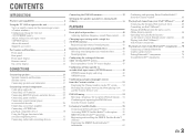
CONTENTS INTRODUCTION Features and capabilities 4 Using the TV OSD to operate the unit 5 View or modify content for the current input source
CONTENTS INTRODUCTION Features and capabilities 4 Using the TV OSD to operate the unit 5 View or modify content for the current input source
Owners Manual
Page 3
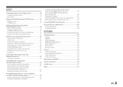
... (Advanced Setup menu 99 Displaying/Setting the Advanced Setup menu 99 Setting the impedance of speakers 99 Avoiding crossing remote control signals when using multiple Yamaha receivers 100 Resetting the SIRIUS Satellite Radio™ parental lock code 100 Changing TV format 101 Removing HDMI video output up-scaling limits......... 101 Initializing...
... (Advanced Setup menu 99 Displaying/Setting the Advanced Setup menu 99 Setting the impedance of speakers 99 Avoiding crossing remote control signals when using multiple Yamaha receivers 100 Resetting the SIRIUS Satellite Radio™ parental lock code 100 Changing TV format 101 Removing HDMI video output up-scaling limits......... 101 Initializing...
Owners Manual
Page 4
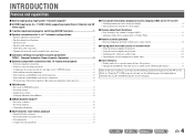
... 18 ■ Automatic settings for each input source External component connection...21 - Speaker cable connection...17 - Configuring the settings specific for speaker acoustic parameters (YPAO - Yamaha Parametric Room Acoustic Optimizer 33 ■ External component connection (max. 16 inputs) and playback - Speaker impedance configuration...18 - Subwoofer cable connection ...20 - Protective cover for...
... 18 ■ Automatic settings for each input source External component connection...21 - Speaker cable connection...17 - Configuring the settings specific for speaker acoustic parameters (YPAO - Yamaha Parametric Room Acoustic Optimizer 33 ■ External component connection (max. 16 inputs) and playback - Speaker impedance configuration...18 - Subwoofer cable connection ...20 - Protective cover for...
Owners Manual
Page 5
Select an input source ...47 - Perform operations such as searching for and registering stations/channels using the TV screen Display information on -screen display (OSD) for selection 57, 64 - Display the list of iPod music sources for the current input source ■ Operate the AM/FM tuner or SIRIUS Satellite Radio - Select a sound program...48 View or modify content for selection 66 - Select a SCENE ...48 - Perform operations such as the Content window that simplifies operations. Display a list of preset stations/channels for the TV screen. Using the TV OSD to...
Select an input source ...47 - Perform operations such as searching for and registering stations/channels using the TV screen Display information on -screen display (OSD) for selection 57, 64 - Display the list of iPod music sources for the current input source ■ Operate the AM/FM tuner or SIRIUS Satellite Radio - Select a sound program...48 View or modify content for selection 66 - Select a SCENE ...48 - Perform operations such as the Content window that simplifies operations. Display a list of preset stations/channels for the TV screen. Using the TV OSD to...

Owners Manual
Page 6
■ HDMI settings - Assign the audio input source for the TV
■ HDMI settings - Assign the audio input source for the TV
Owners Manual
Page 7
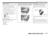
Design and specifications are subject to production. ac Battery compartment cover b Battery compartment Replace the batteries with new ones, and set the remote control codes. NOTE If there are remote control codes for external components registered to the remote control, removing the batteries for the information about each position of the parts. • J1 indicates that the reference is created prior to change in the remote control, may clear the remote control codes. If this manual • Some features are not available in "Part names and functions." Attach the cover ...
Design and specifications are subject to production. ac Battery compartment cover b Battery compartment Replace the batteries with new ones, and set the remote control codes. NOTE If there are remote control codes for external components registered to the remote control, removing the batteries for the information about each position of the parts. • J1 indicates that the reference is created prior to change in the remote control, may clear the remote control codes. If this manual • Some features are not available in "Part names and functions." Attach the cover ...
Owners Manual
Page 8
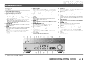
m PHONES jack For plugging headphones in the Yamaha iPod universal dock, is charging while the unit is enabled and audio/video from which is placed in . Press either the left or right key ... the headphones. Press the left or right key repeatedly to this unit, this unit (☞p. 68). b HDMI Through/iPod Charge indicator Lights up when the Yamaha iPod wireless receiver is connected to this key switches that amplifier between on the front panel display (☞p. 10). J1 i FM/AM (CATEGORY l / h) Sets the...
m PHONES jack For plugging headphones in the Yamaha iPod universal dock, is charging while the unit is enabled and audio/video from which is placed in . Press either the left or right key ... the headphones. Press the left or right key repeatedly to this unit, this unit (☞p. 68). b HDMI Through/iPod Charge indicator Lights up when the Yamaha iPod wireless receiver is connected to this key switches that amplifier between on the front panel display (☞p. 10). J1 i FM/AM (CATEGORY l / h) Sets the...

Owners Manual
Page 9
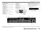
... to receive audio/video signals (☞p. 25). i SIRIUS jack For connecting a SiriusConnect tuner (sold separately) (☞p. 58). Rear panel a DOCK jack For connecting an optional Yamaha iPod universal dock (such as the AV5-6 or AUDIO1-2 are selected (☞p. 31). d MONITOR OUT jacks VIDEO jack COMPONENT VIDEO jacks For connecting a TV capable...
... to receive audio/video signals (☞p. 25). i SIRIUS jack For connecting a SiriusConnect tuner (sold separately) (☞p. 58). Rear panel a DOCK jack For connecting an optional Yamaha iPod universal dock (such as the AV5-6 or AUDIO1-2 are selected (☞p. 31). d MONITOR OUT jacks VIDEO jack COMPONENT VIDEO jacks For connecting a TV capable...
Owners Manual
Page 10
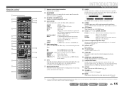
h ZONE2 indicator Lights up when a sound field effect that uses CINEMA DSP technology is selected. En 10 f Tuner indicator Light up according to the status of the input source. j VOLUME indicator Displays the current volume level. Front panel display a HDMI indicator Lights up during normal HDMI communication when any of the HDMI1-5 inputs are output. c CINEMA DSP indicator Lights up when the audio output to cycle through input source J2 → sound program → surround decoder in order. e CINEMA DSP 3D indicator Lights up when the Compressed Music Enhancer ...
h ZONE2 indicator Lights up when a sound field effect that uses CINEMA DSP technology is selected. En 10 f Tuner indicator Light up according to the status of the input source. j VOLUME indicator Displays the current volume level. Front panel display a HDMI indicator Lights up during normal HDMI communication when any of the HDMI1-5 inputs are output. c CINEMA DSP indicator Lights up when the audio output to cycle through input source J2 → sound program → surround decoder in order. e CINEMA DSP 3D indicator Lights up when the Compressed Music Enhancer ...
Owners Manual
Page 11
... an external component on the front panel display (the name of time has elapsed (sleep timer). J1 MULTI CH INPUT MULTI CH INPUT jacks DOCK A Yamaha iPod universal dock, iPod wireless receiver, or Bluetooth wireless audio receiver TUNER connected to the SIRIUS jack. FM/AM tuner SIRIUS A SIRIUS tuner connected to...
... an external component on the front panel display (the name of time has elapsed (sleep timer). J1 MULTI CH INPUT MULTI CH INPUT jacks DOCK A Yamaha iPod universal dock, iPod wireless receiver, or Bluetooth wireless audio receiver TUNER connected to the SIRIUS jack. FM/AM tuner SIRIUS A SIRIUS tuner connected to...
Owners Manual
Page 12
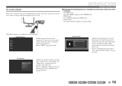
Use this menu to select desired settings, change their values, or check the current status of the source from which music is connected to "Confirming and operating input sources from the Content browse view. Refer to this unit on the TV screen. ON SCREEN menu Detailed settings for music content from the Content window" (☞p. 53) for details. Refer to "Configuring settings specific to "SETUP" (☞p. 72) for each input source. En 12 On-screen display When a TV is currently played back. Refer to an individual input source (OPTION menu)" (☞p. 49) for ...
Use this menu to select desired settings, change their values, or check the current status of the source from which music is connected to "Confirming and operating input sources from the Content browse view. Refer to this unit on the TV screen. ON SCREEN menu Detailed settings for music content from the Content window" (☞p. 53) for details. Refer to "Configuring settings specific to "SETUP" (☞p. 72) for each input source. En 12 On-screen display When a TV is currently played back. Refer to an individual input source (OPTION menu)" (☞p. 49) for ...

Owners Manual
Page 13
When used with 6.1ch sound, sound from the left and right sound surround back speakers is equipped with built-in amplifier. Ex. Presence speaker layout: Place the left and right presence speakers 1.6 - 3.3 ft. (0.5 - 1 m) to the outside of the TV and the speaker aligned. The tops of the listening position. Surround back speaker layout: When used for right and left rear-area is output. ■ Surround back left and right surround speakers. Front speaker layout: Place these to the rear of the room. Ex. Use a subwoofer that is mixed and output from the ...
When used with 6.1ch sound, sound from the left and right sound surround back speakers is equipped with built-in amplifier. Ex. Presence speaker layout: Place the left and right presence speakers 1.6 - 3.3 ft. (0.5 - 1 m) to the outside of the TV and the speaker aligned. The tops of the listening position. Surround back speaker layout: When used for right and left rear-area is output. ■ Surround back left and right surround speakers. Front speaker layout: Place these to the rear of the room. Ex. Use a subwoofer that is mixed and output from the ...

Owners Manual
Page 14
Speaker jacks EXTRA SP jack FRONT L/R, CENTER, SURROUND L/R, SURROUND BACK L/R, SUBWOOFER No used Center speaker Surround speaker L Surround back speaker L 12 in (30 cm) or more Surround back speaker R This unit automatically selects the presence speakers or surround back speakers to output sounds according to the speaker layout. Speakers for a richer sound field effect ■ Presence speaker layout (7 speakers + subwoofer + presence speakers) Front speaker R Front speaker L Presence speaker L Presence speaker R Subwoofer Surround speaker R ■ Connections of ...
Speaker jacks EXTRA SP jack FRONT L/R, CENTER, SURROUND L/R, SURROUND BACK L/R, SUBWOOFER No used Center speaker Surround speaker L Surround back speaker L 12 in (30 cm) or more Surround back speaker R This unit automatically selects the presence speakers or surround back speakers to output sounds according to the speaker layout. Speakers for a richer sound field effect ■ Presence speaker layout (7 speakers + subwoofer + presence speakers) Front speaker R Front speaker L Presence speaker L Presence speaker R Subwoofer Surround speaker R ■ Connections of ...

Owners Manual
Page 15
Refer to "Front/Center/Surround/Surround back speaker and Subwoofer connection" and "Bi-amp connection" for a high quality sound ■ 5-channel speaker layout (Front speakers (Bi-amp) + 3 speakers) Front speaker L (Bi-amp connection) Front speaker R (Bi-amp connection) Subwoofer Surround speaker R CONNECTIONS Connecting speakers ■ Connections of speakers Connect the speakers to the following jacks according to the speaker layout. This enables 7.1-channel sound without surround back speakers ■ 5.1-channel speaker layout (5 speakers + subwoofer) Front speaker R ...
Refer to "Front/Center/Surround/Surround back speaker and Subwoofer connection" and "Bi-amp connection" for a high quality sound ■ 5-channel speaker layout (Front speakers (Bi-amp) + 3 speakers) Front speaker L (Bi-amp connection) Front speaker R (Bi-amp connection) Subwoofer Surround speaker R CONNECTIONS Connecting speakers ■ Connections of speakers Connect the speakers to the following jacks according to the speaker layout. This enables 7.1-channel sound without surround back speakers ■ 5.1-channel speaker layout (5 speakers + subwoofer) Front speaker R ...

Owners Manual
Page 16
When the built-in amplifier for details on , the speakers that output the sound are switched from the surround back speakers to the speakers in another room can also be output from both the surround back speakers and the speakers in the second zone at the same time. J1 ■ Connections of this unit according to the speaker configuration (☞p. 84). CONNECTIONS Connecting speakers En 16 Refer to "Front/Center/Surround/Surround back speaker and Subwoofer connection" and "Multi-zone audio system using the internal amplifier of speakers Connect the speakers to the following ...
When the built-in amplifier for details on , the speakers that output the sound are switched from the surround back speakers to the speakers in another room can also be output from both the surround back speakers and the speakers in the second zone at the same time. J1 ■ Connections of this unit according to the speaker configuration (☞p. 84). CONNECTIONS Connecting speakers En 16 Refer to "Front/Center/Surround/Surround back speaker and Subwoofer connection" and "Multi-zone audio system using the internal amplifier of speakers Connect the speakers to the following ...
Owners Manual
Page 17
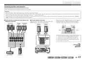
Connecting speakers and subwoofer CONNECTIONS Connecting speakers Connect your speakers to the next page En 17 If the speaker cables short circuit, "CHECK SP WIRES!" With the sound programs (☞p. 45), sound with the metal areas of CINEMA DSP sound programs. • Although you can be created. 0.5 - 1 m PL 0.5 - 1 m PR 1.8 m FL FR 1.8 m HDMI 2 MOTE HDMI 3 FRONT HDMI 4 CENTER HDMI 5 SURROUND SURROUND BACK/BI-AMP SINGLE +12V 0.1A MAX. This may damage this unit is switched on this unit, you cannot output sounds from the power outlet before connecting the speakers....
Connecting speakers and subwoofer CONNECTIONS Connecting speakers Connect your speakers to the next page En 17 If the speaker cables short circuit, "CHECK SP WIRES!" With the sound programs (☞p. 45), sound with the metal areas of CINEMA DSP sound programs. • Although you can be created. 0.5 - 1 m PL 0.5 - 1 m PR 1.8 m FL FR 1.8 m HDMI 2 MOTE HDMI 3 FRONT HDMI 4 CENTER HDMI 5 SURROUND SURROUND BACK/BI-AMP SINGLE +12V 0.1A MAX. This may damage this unit is switched on this unit, you cannot output sounds from the power outlet before connecting the speakers....
Owners Manual
Page 18
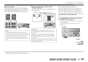
Configure the bi-amp settings to the standby mode. 2 Press MAIN ZONE A while pressing and holding STRAIGHT on the Advanced Setup menu. FRONT SURROUND BACK/BI-AMP SINGLE NOTES • Before making bi-amplification connections, make sure that can be configured as in amplifier damage. CONNECTIONS Connecting speakers ■ Changing speaker impedance This unit is configured for all channels must be maintained at the factory setting. En 18 When this unit is found on the front panel display. When connecting speakers, connect the FRONT jacks and the SURROUND BACK/BI-AMP ...
Configure the bi-amp settings to the standby mode. 2 Press MAIN ZONE A while pressing and holding STRAIGHT on the Advanced Setup menu. FRONT SURROUND BACK/BI-AMP SINGLE NOTES • Before making bi-amplification connections, make sure that can be configured as in amplifier damage. CONNECTIONS Connecting speakers ■ Changing speaker impedance This unit is configured for all channels must be maintained at the factory setting. En 18 When this unit is found on the front panel display. When connecting speakers, connect the FRONT jacks and the SURROUND BACK/BI-AMP ...

Owners Manual
Page 19
The power turns on the front panel. is displayed on , when the settings you made has been configured. 3 2 FRONT 1 4 CONNECTIONS Connecting speakers 4 Tighten the terminal. FRONT Banana plug 1 Remove approximately 0.4 in. (10 mm) of insulation from the ends of the speaker cables, and twist the bare wires of the cables together firmly so that "SP IMP." En 19 Connecting the banana plug Tighten the knob, and then insert the banana plug into the gap on the side of the terminal. SP IMP. -8 MIN 4 Press STRAIGHT repeatedly to select a "6ΩMIN." ■ Connecting speakers This ...
The power turns on the front panel. is displayed on , when the settings you made has been configured. 3 2 FRONT 1 4 CONNECTIONS Connecting speakers 4 Tighten the terminal. FRONT Banana plug 1 Remove approximately 0.4 in. (10 mm) of insulation from the ends of the speaker cables, and twist the bare wires of the cables together firmly so that "SP IMP." En 19 Connecting the banana plug Tighten the knob, and then insert the banana plug into the gap on the side of the terminal. SP IMP. -8 MIN 4 Press STRAIGHT repeatedly to select a "6ΩMIN." ■ Connecting speakers This ...

Owners Manual
Page 20
VOLUME CROSSOVER/ HIGH CUT MIN MAX MIN MAX Subwoofer examples NOTE After connection, applying this setting to this unit with an audio pin cable. 2 Set the subwoofer volume as follows. With using "Power Amp Assign" function, you can connect to the following speakers. • Presence L/R speakers • Zone2 speakers ■ Connecting the subwoofer Red: positive (+) Black: negative (-) EX ZPOR 1 Press down the tab and insert the bare end of the speaker cable into the hole in the terminal. 2 Release the tab to secure the wire. 1 Connect the subwoofer input jack to activate all ...
VOLUME CROSSOVER/ HIGH CUT MIN MAX MIN MAX Subwoofer examples NOTE After connection, applying this setting to this unit with an audio pin cable. 2 Set the subwoofer volume as follows. With using "Power Amp Assign" function, you can connect to the following speakers. • Presence L/R speakers • Zone2 speakers ■ Connecting the subwoofer Red: positive (+) Black: negative (-) EX ZPOR 1 Press down the tab and insert the bare end of the speaker cable into the hole in the terminal. 2 Release the tab to secure the wire. 1 Connect the subwoofer input jack to activate all ...
