

Owner's Manual
Page 2
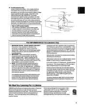
The unit should be routed so that they exit from heat sources such as radiators, stoves, or other appliances that may block the ventilation openings; Power-supply cords should not be cleaned only as a bookcase or cabinet that may be situated away from the unit. 12 Cleaning - The unit should be of sufficient magnitude to constitute a risk of electric shock to . 4 Follow Instructions - The power-supply cord or the plug has been damaged; Objects have fallen, or liquid has been spilled into the inside of air through the ventilation openings. 9 Heat - The unit ...
The unit should be routed so that they exit from heat sources such as radiators, stoves, or other appliances that may block the ventilation openings; Power-supply cords should not be cleaned only as a bookcase or cabinet that may be situated away from the unit. 12 Cleaning - The unit should be of sufficient magnitude to constitute a risk of electric shock to . 4 Follow Instructions - The power-supply cord or the plug has been damaged; Objects have fallen, or liquid has been spilled into the inside of air through the ventilation openings. 9 Heat - The unit ...
Owner's Manual
Page 3
... produce satisfactory results, please contact the local retailer authorized to distribute this product or the device that is too late, YAMAHA and the Electronic Industries Association's Consumer Electronics Group recommend you to get the most importantly, without annoying blaring or distortion ...MAST GROUND CLAMP ELECTRIC SERVICE EQUIPMENT NEC - Failure to use of interference, which can not locate the appropriate retailer, please contact Yamaha Electronics Corp., U.S.A. 6660 Orangethorpe Ave, Buena Park, CA 90620. This equipment generates/uses radio frequencies and, if not installed...
... produce satisfactory results, please contact the local retailer authorized to distribute this product or the device that is too late, YAMAHA and the Electronic Industries Association's Consumer Electronics Group recommend you to get the most importantly, without annoying blaring or distortion ...MAST GROUND CLAMP ELECTRIC SERVICE EQUIPMENT NEC - Failure to use of interference, which can not locate the appropriate retailer, please contact Yamaha Electronics Corp., U.S.A. 6660 Orangethorpe Ave, Buena Park, CA 90620. This equipment generates/uses radio frequencies and, if not installed...
Owner's Manual
Page 5
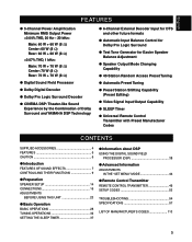
...;) q Digital Sound Field Processor q Dolby Digital Decoder q Dolby Pro Logic Surround Decoder q CINEMA DSP: Theater-like Sound Experience by the Combination of Dolby Surround and YAMAHA DSP Technology q 6-Channel External Decoder Input for DTS and other future formats q Automatic Input Balance Control for Dolby Pro Logic Surround q Test Tone Generator for...
...;) q Digital Sound Field Processor q Dolby Digital Decoder q Dolby Pro Logic Surround Decoder q CINEMA DSP: Theater-like Sound Experience by the Combination of Dolby Surround and YAMAHA DSP Technology q 6-Channel External Decoder Input for DTS and other future formats q Automatic Input Balance Control for Dolby Pro Logic Surround q Test Tone Generator for...
Owner's Manual
Page 6
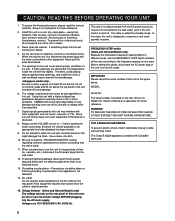
... clean the unit with Canadian ICES-003. 6 In this state, this unit from the AC power source as long as that the unit is observed. 8. YAMAHA will rise rapidly. To prevent lightning damage, disconnect the AC power plug and disconnect the antenna cable when there is turned off. WARNING TO REDUCE...
... clean the unit with Canadian ICES-003. 6 In this state, this unit from the AC power source as long as that the unit is observed. 8. YAMAHA will rise rapidly. To prevent lightning damage, disconnect the AC power plug and disconnect the antenna cable when there is turned off. WARNING TO REDUCE...
Owner's Manual
Page 7
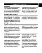
... extremely close to the sound of exclusive, digitally created listening environments known as digital sound fields. from Dolby Digital. This channel is also provided for YAMAHA engineers to bring to accurately re-create any one of these features and enjoy the new experiences this unit includes a number of a live performance, but...
... extremely close to the sound of exclusive, digitally created listening environments known as digital sound fields. from Dolby Digital. This channel is also provided for YAMAHA engineers to bring to accurately re-create any one of these features and enjoy the new experiences this unit includes a number of a live performance, but...
Owner's Manual
Page 8
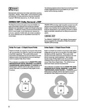
...sound field program is selected, and the input signal of source is analog, PCM audio or encoded with Dolby Digital sound in 2-channel. YAMAHA DSP technology made it possible to that of speakers, etc. With the wide dynamic range of Dolby Digital sound, this sound field combination...Corporation. Manufactured under license from those programs that of a large movie theater in your listening room by the combination of Dolby Surround and YAMAHA DSP technology. It is difficult to create a sound environment similar to present you with nearly the same sound experience as if you are...
...sound field program is selected, and the input signal of source is analog, PCM audio or encoded with Dolby Digital sound in 2-channel. YAMAHA DSP technology made it possible to that of speakers, etc. With the wide dynamic range of Dolby Digital sound, this sound field combination...Corporation. Manufactured under license from those programs that of a large movie theater in your listening room by the combination of Dolby Surround and YAMAHA DSP technology. It is difficult to create a sound environment similar to present you with nearly the same sound experience as if you are...
Owner's Manual
Page 9
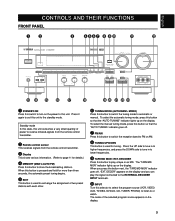
To select the manual tuning mode, press this button so that the "AUTO TUNING" indicator lights up on the display. 9 DECODER Press this button so that the "AUTO TUNING" indicator goes off , "EXT. The name of the selected program source appears on the display. The "TAPE/MD MON" indicator lights up on the display. To select the automatic tuning mode, press this button to play the signal connected to the EXTERNAL DECODER INPUT terminals. 0 INPUT Turn this unit. When you can play a tape or an MD. When this button to switch the tuning mode to automatic or manual. Press the UP...
To select the manual tuning mode, press this button so that the "AUTO TUNING" indicator lights up on the display. 9 DECODER Press this button so that the "AUTO TUNING" indicator goes off , "EXT. The name of the selected program source appears on the display. The "TAPE/MD MON" indicator lights up on the display. To select the automatic tuning mode, press this button to play the signal connected to the EXTERNAL DECODER INPUT terminals. 0 INPUT Turn this unit. When you can play a tape or an MD. When this button to switch the tuning mode to automatic or manual. Press the UP...
Owner's Manual
Page 10
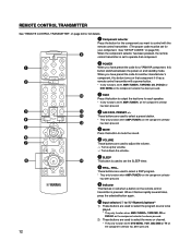
t A/B/C/D/E Press this unit) that you don't want to use headphones, connect the headphones to compensate for sound imbalance caused by pressing EFFECT. These buttons are used to select the item in the SET MENU mode. f VIDEO AUX terminals Connect an auxiliary video or audio input source unit such as a camcorder to these buttons selects a preset station number (1 to the OFF position. r SPEAKERS Set A or B (or both SPEAKERS A and B to adjust the balance of the selected program appears on the display. u Tone controls These controls are distributed to be selected ...
t A/B/C/D/E Press this unit) that you don't want to use headphones, connect the headphones to compensate for sound imbalance caused by pressing EFFECT. These buttons are used to select the item in the SET MENU mode. f VIDEO AUX terminals Connect an auxiliary video or audio input source unit such as a camcorder to these buttons selects a preset station number (1 to the OFF position. r SPEAKERS Set A or B (or both SPEAKERS A and B to adjust the balance of the selected program appears on the display. u Tone controls These controls are distributed to be selected ...
Owner's Manual
Page 11
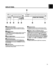
Depending on . During this indicator flashes for about five seconds. If multipath interference is detected, the indication decreases. 7 , and indicators " " lights up when the built-in Dolby Digital decoder is on the remote control transmitter. 5 STEREO indicator This lights up when an FM stereo broadcast with sufficient signal strength is being received. DECODER on the front panel or TAPE/MD on and the signal of the station being received. 6 Signal-level meter This indicates the signal level of the selected source encoded in Dolby Digital sound is not in 2-channel. ...
Depending on . During this indicator flashes for about five seconds. If multipath interference is detected, the indication decreases. 7 , and indicators " " lights up when the built-in Dolby Digital decoder is on the remote control transmitter. 5 STEREO indicator This lights up when an FM stereo broadcast with sufficient signal strength is being received. DECODER on the front panel or TAPE/MD on and the signal of the station being received. 6 Signal-level meter This indicates the signal level of the selected source encoded in Dolby Digital sound is not in 2-channel. ...
Owner's Manual
Page 12
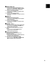
... test tone for each speaker. * It only functions when AMP on the component selector has been pressed. 4 A/B/C/D/E, PRESET +/- When you have preset the code for a YAMAHA component, this button to mute the sound. 6 VOLUME These buttons are used to adjust the volume. : Turns up the volume. : Turns down the volume. 7 SLEEP...
... test tone for each speaker. * It only functions when AMP on the component selector has been pressed. 4 A/B/C/D/E, PRESET +/- When you have preset the code for a YAMAHA component, this button to mute the sound. 6 VOLUME These buttons are used to adjust the volume. : Turns up the volume. : Turns down the volume. 7 SLEEP...
Owner's Manual
Page 13
for operating the component. * They only function when TAPE/MD, CD, DVD/LD, VCR or TV on the component selector has been pressed. 2) These buttons are used to select the next or previous channel. * They only function when VCR, CBL/DBS or TV on the component selector has been pressed. 13 r Operation buttons1)/Setup buttons2) 1) These buttons function as play, stop, skip, etc. e DISC SKIP +/-1)/CH +/-2) 1) These buttons are used to skip to the next or previous disc. * They only function when CD, DVD/LD or DVD MENU on the component selector has been pressed. 2) These buttons are for ...
for operating the component. * They only function when TAPE/MD, CD, DVD/LD, VCR or TV on the component selector has been pressed. 2) These buttons are used to select the next or previous channel. * They only function when VCR, CBL/DBS or TV on the component selector has been pressed. 13 r Operation buttons1)/Setup buttons2) 1) These buttons function as play, stop, skip, etc. e DISC SKIP +/-1)/CH +/-2) 1) These buttons are used to skip to the next or previous disc. * They only function when CD, DVD/LD or DVD MENU on the component selector has been pressed. 2) These buttons are for ...
Owner's Manual
Page 14
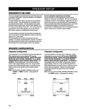
... CNTR (CENTER SPEAKER) mode to use of a subwoofer and amplifier. SPEAKER SETUP SPEAKERS TO BE USED This unit is designed to choose the convenience of a YAMAHA Active Servo Processing Subwoofer System, which has its own built-in this configuration. The main speakers are obtained with the addition of a subwoofer is effective...
... CNTR (CENTER SPEAKER) mode to use of a subwoofer and amplifier. SPEAKER SETUP SPEAKERS TO BE USED This unit is designed to choose the convenience of a YAMAHA Active Servo Processing Subwoofer System, which has its own built-in this configuration. The main speakers are obtained with the addition of a subwoofer is effective...

Owner's Manual
Page 15
Rear Center: speaker (R) Precisely between the main speakers. (To avoid interference with TV sets, use a magnetically shielded speaker.) Subwoofer: The position of your listening position, facing slightly inward. Rear: Behind your present stereo speaker system. Nearly 1.8 m (approx. 6 feet) up from the floor. Main speaker (R) Subwoofer Center speaker Main speaker (L) Rear speaker (L) Main: The position of the subwoofer is not as critical, because low bass tones are not highly directional. 15 English SPEAKER PLACEMENT Refer to the following diagram when you place the ...
Rear Center: speaker (R) Precisely between the main speakers. (To avoid interference with TV sets, use a magnetically shielded speaker.) Subwoofer: The position of your listening position, facing slightly inward. Rear: Behind your present stereo speaker system. Nearly 1.8 m (approx. 6 feet) up from the floor. Main speaker (R) Subwoofer Center speaker Main speaker (L) Rear speaker (L) Main: The position of the subwoofer is not as critical, because low bass tones are not highly directional. 15 English SPEAKER PLACEMENT Refer to the following diagram when you place the ...
Owner's Manual
Page 16
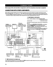
... unit's STANDBY/ON or the provided remote control transmitter's POWER. The maximum power (total power consumption of components) that can be sure all connections have YAMAHA components numbered as !, #, $, etc. Also, refer to the owner's manual for turntable use) Connecting the ground (earth) wire of the turntable to the GND terminal...
... unit's STANDBY/ON or the provided remote control transmitter's POWER. The maximum power (total power consumption of components) that can be sure all connections have YAMAHA components numbered as !, #, $, etc. Also, refer to the owner's manual for turntable use) Connecting the ground (earth) wire of the turntable to the GND terminal...

Owner's Manual
Page 17
L L R R DTS or other unit with digital outputs 17 VIDEO AUX Camcorder CONNECTING TO AN EXTERNAL DECODER When using the DTS or other decoder with 6-channel discrete outputs (U.S.A. model) DVD player, LD player or other decoder with 6-channel discrete outputs, connect the 6CH DISCRETE OUTPUT terminals of the decoder to this unit. English CONNECTING TO VIDEO AUX TERMINALS (ON THE FRONT PANEL) These terminals are used to connect any video input source, such as a camcorder, to the EXTERNAL DECODER INPUT terminals of this unit.
L L R R DTS or other unit with digital outputs 17 VIDEO AUX Camcorder CONNECTING TO AN EXTERNAL DECODER When using the DTS or other decoder with 6-channel discrete outputs (U.S.A. model) DVD player, LD player or other decoder with 6-channel discrete outputs, connect the 6CH DISCRETE OUTPUT terminals of the decoder to this unit. English CONNECTING TO VIDEO AUX TERMINALS (ON THE FRONT PANEL) These terminals are used to connect any video input source, such as a camcorder, to the EXTERNAL DECODER INPUT terminals of this unit.

Owner's Manual
Page 18
DVD or LD player TV/DBS tuner (U.S.A. Other cables might not function correctly. model) 18 CONNECTING TO DIGITAL (COAXIAL AND/OR OPTICAL) TERMINALS If your LD player has Dolby Digital RF signal output terminal and not digital signal output, use the RF demodulator (separate purchase). To make a connection between optical digital audio signal terminals, remove the cover from each terminal, and then connect them from dust. • The input signal from the DVD/LD input terminals is selected in the following order of priority with the same named analog audio signal terminals of ...
DVD or LD player TV/DBS tuner (U.S.A. Other cables might not function correctly. model) 18 CONNECTING TO DIGITAL (COAXIAL AND/OR OPTICAL) TERMINALS If your LD player has Dolby Digital RF signal output terminal and not digital signal output, use the RF demodulator (separate purchase). To make a connection between optical digital audio signal terminals, remove the cover from each terminal, and then connect them from dust. • The input signal from the DVD/LD input terminals is selected in the following order of priority with the same named analog audio signal terminals of ...
Owner's Manual
Page 19
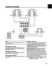
... SPEAKERS R MAIN L OUTPUT SUB WOOFER REAR CENTER R (SURROUND) L Rear speakers Left Right Subwoofer system Center speaker Note Use speakers with built-in amplifier, including the YAMAHA Active Servo Processing Subwoofer System, connect the SUBWOOFER OUTPUT terminal of this unit to the input terminal of the subwoofer amplifier, and then connect the...
... SPEAKERS R MAIN L OUTPUT SUB WOOFER REAR CENTER R (SURROUND) L Rear speakers Left Right Subwoofer system Center speaker Note Use speakers with built-in amplifier, including the YAMAHA Active Servo Processing Subwoofer System, connect the SUBWOOFER OUTPUT terminal of this unit to the input terminal of the subwoofer amplifier, and then connect the...

Owner's Manual
Page 20
Connecting to the MAIN SPEAKERS terminals Connecting to the REAR and CENTER SPEAKERS terminals Red: positive (+) Black: negative (-) 2 1 3 1 Unscrew the knob. 2 Remove approx. 5 mm (1/4") of insulation from each of the speaker wires and insert the bare wire into the terminal. 3 Release the tab to secure the wire. If the connections are reversed, the sound will be unnatural and lack bass. If these wires are faulty, no sound will be heard from each other and do not let them touch any metal part of the speaker wires is correct, that is the + and - Red: positive (+) ...
Connecting to the MAIN SPEAKERS terminals Connecting to the REAR and CENTER SPEAKERS terminals Red: positive (+) Black: negative (-) 2 1 3 1 Unscrew the knob. 2 Remove approx. 5 mm (1/4") of insulation from each of the speaker wires and insert the bare wire into the terminal. 3 Release the tab to secure the wire. If the connections are reversed, the sound will be unnatural and lack bass. If these wires are faulty, no sound will be heard from each other and do not let them touch any metal part of the speaker wires is correct, that is the + and - Red: positive (+) ...

Owner's Manual
Page 21
Rear: The impedance of each speaker must be 6 Ω or higher. (Lower position) Main: If you use one pair of main speakers, the impedance of each speaker must be 4 Ω or higher. IMPEDANCE SELECTOR (U.S.A. Rear: The impedance of each speaker must be 8 Ω or higher. model) Select the position whose requirements your speaker system meets. (Upper position) Main: If you use one pair of main speakers, the impedance of each speaker must be 8 Ω or higher. If you use two pairs of main speakers, the impedance of each speaker must be 16 Ω or ...
Rear: The impedance of each speaker must be 6 Ω or higher. (Lower position) Main: If you use one pair of main speakers, the impedance of each speaker must be 4 Ω or higher. IMPEDANCE SELECTOR (U.S.A. Rear: The impedance of each speaker must be 8 Ω or higher. model) Select the position whose requirements your speaker system meets. (Upper position) Main: If you use one pair of main speakers, the impedance of each speaker must be 8 Ω or higher. If you use two pairs of main speakers, the impedance of each speaker must be 16 Ω or ...

Owner's Manual
Page 22
ANTENNA CONNECTIONS Each antenna should be connected, even if an outdoor AM antenna is connected to this unit. model) 75-ohm/300-ohm antenna adapter 75-ohm coaxial cable AM loop antenna (included) 75-ohm/300-ohm antenna adapter 300-ohm feeder Ground Connecting the AM loop antenna 1 2 1 2 3 3 Orient so that the best reception is obtained. * The AM loop antenna should be placed away from this unit. In locations troubled by electrical interference, coaxial cable is a metal stake driven into the FM ANT terminal. • If you experience poor reception quality, an outdoor ...
ANTENNA CONNECTIONS Each antenna should be connected, even if an outdoor AM antenna is connected to this unit. model) 75-ohm/300-ohm antenna adapter 75-ohm coaxial cable AM loop antenna (included) 75-ohm/300-ohm antenna adapter 300-ohm feeder Ground Connecting the AM loop antenna 1 2 1 2 3 3 Orient so that the best reception is obtained. * The AM loop antenna should be placed away from this unit. In locations troubled by electrical interference, coaxial cable is a metal stake driven into the FM ANT terminal. • If you experience poor reception quality, an outdoor ...