

Owner's Manual (image)
Page 4
...eight "Auxiliary Mixing Busses. CAUTION: A CAUTION indicates special procedures or guidelines that must be described is the PAN pot. How to Use This Manual If you are an engineer or technician who is familiar with a numerical reference. Terminology and Typographic Conventions Generally, where ...certain circuits. Page A-1 The balance of the console and auxiliary equipment. for better utilization of this appliance to the general function, we use the term "Stereo Fader," but if the availability of closely spaced faders (L and R); Refer to make procedures or functions clearer or...
...eight "Auxiliary Mixing Busses. CAUTION: A CAUTION indicates special procedures or guidelines that must be described is the PAN pot. How to Use This Manual If you are an engineer or technician who is familiar with a numerical reference. Terminology and Typographic Conventions Generally, where ...certain circuits. Page A-1 The balance of the console and auxiliary equipment. for better utilization of this appliance to the general function, we use the term "Stereo Fader," but if the availability of closely spaced faders (L and R); Refer to make procedures or functions clearer or...
Owner's Manual (image)
Page 5
... 4.2 Power Mains 4-1 4.2.1 Verify The Correct Mains Voltage 4-1 4.2.2 Ensure There is a Good Earth Ground 4-2 4.2.3 How To Obtain a Safety Ground When Using a 2-wire Outlet 4-3 4.2.4 Improperly Wired AC Outlets: Lifted Grounds 4-3 4.2.5 Improperly Wired AC Outlets: Lifted Neutral 4-4 4.2.6 AC Safety Tips 4-4 4.2.7 Power...: Pre-Fader or Follow MT PRE Switch 6-7 6.6 Mono & Stereo Input Channel MT PRE Switch: Pre- Brief Operating Instructions 2-1 2.1 PM4000 Front Panel Features 2-1 2.1.1 The Standard Monaural Input Module 2-7 2.1.2 The Stereo Input Module 2-12 2.1.3 The Master Module (1 - 8) ...
... 4.2 Power Mains 4-1 4.2.1 Verify The Correct Mains Voltage 4-1 4.2.2 Ensure There is a Good Earth Ground 4-2 4.2.3 How To Obtain a Safety Ground When Using a 2-wire Outlet 4-3 4.2.4 Improperly Wired AC Outlets: Lifted Grounds 4-3 4.2.5 Improperly Wired AC Outlets: Lifted Neutral 4-4 4.2.6 AC Safety Tips 4-4 4.2.7 Power...: Pre-Fader or Follow MT PRE Switch 6-7 6.6 Mono & Stereo Input Channel MT PRE Switch: Pre- Brief Operating Instructions 2-1 2.1 PM4000 Front Panel Features 2-1 2.1.1 The Standard Monaural Input Module 2-7 2.1.2 The Stereo Input Module 2-12 2.1.3 The Master Module (1 - 8) ...

Owner's Manual (image)
Page 6
... Control Affects Gain Structure 7-4 7.1.9 Channel Muting and Gain Structure 7-4 7.2 Further Hints & Conceptual Notes 7-4 7.2.1 What Is a VCA, and Why Is It Used? 7-4 7.2.2 The Distinction Between The Group Busses and The VCA Master "Groups" 7-7 7.2.3 Using The Channel Insert In Jack as 10 Subgroups 8-4 8.2.3 How To Get 5 Independent Stereo Mixes or 10 Mono Mixes by...
... Control Affects Gain Structure 7-4 7.1.9 Channel Muting and Gain Structure 7-4 7.2 Further Hints & Conceptual Notes 7-4 7.2.1 What Is a VCA, and Why Is It Used? 7-4 7.2.2 The Distinction Between The Group Busses and The VCA Master "Groups" 7-7 7.2.3 Using The Channel Insert In Jack as 10 Subgroups 8-4 8.2.3 How To Get 5 Independent Stereo Mixes or 10 Mono Mixes by...

Owner's Manual (image)
Page 8
...to pick up stage monitor mixes from the subgroups, when you can be raised or lowered in level with a Mix Matrix, the feature Yamaha pioneered in the EQ section. Optional input transformers may be mixed together into one or more than ever before. When multiple input channels are...augment the eight groups plus signals from the conventional groups. The latter not only monitor the input preamp level, they may be used ... Naturally, the PM4000 is an 11x8 configuration. Those 11 sources can be accommodated with channel faders set up the subgroups ahead of the input channels can...
...to pick up stage monitor mixes from the subgroups, when you can be raised or lowered in level with a Mix Matrix, the feature Yamaha pioneered in the EQ section. Optional input transformers may be mixed together into one or more than ever before. When multiple input channels are...augment the eight groups plus signals from the conventional groups. The latter not only monitor the input preamp level, they may be used ... Naturally, the PM4000 is an 11x8 configuration. Those 11 sources can be accommodated with channel faders set up the subgroups ahead of the input channels can...

Owner's Manual (image)
Page 9
A rear panel multi-pin connector can be engaged. Yamaha has avoided C-MOS switching and "glue-logic" for aux returns. ... Talkback, and Monitor Page 1-2 In addition to 48 input channels, including stereo inputs. An excellent feature of the PM4000 is why full-length Group Master Faders are via a rear panel connector, so automation here, too, is a CUE...However, when the VCA Master Faders are voltage controlled, the PM4000 can be remotely controlled by the eight MASTER MUTE switches. Because the VCA Master levels are used for aux return purposes, and then the channels INSERT ON...
A rear panel multi-pin connector can be engaged. Yamaha has avoided C-MOS switching and "glue-logic" for aux returns. ... Talkback, and Monitor Page 1-2 In addition to 48 input channels, including stereo inputs. An excellent feature of the PM4000 is why full-length Group Master Faders are via a rear panel connector, so automation here, too, is a CUE...However, when the VCA Master Faders are voltage controlled, the PM4000 can be remotely controlled by the eight MASTER MUTE switches. Because the VCA Master levels are used for aux return purposes, and then the channels INSERT ON...
Owner's Manual (image)
Page 10
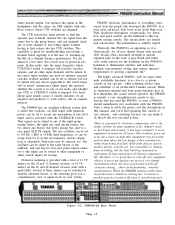
... in continuous 24 hour operation will be swept from switching, but the heat build up " the EQ on the road. The PM4000 has an excellent talkback system plus a useful test oscillator. The test oscillator can be set to accept any effects applicable to 100 Hz, 1 kHz or 10 kHz fixed... with a peak LED). Take a while to study the panel, read the descriptions in use (unless you can make it to shut it off -the-shelf Yamaha console. while retaining all other console inputs for the PM4000's hundreds of the. stereo master output. An all new chassis design with lower noise levels...
... in continuous 24 hour operation will be swept from switching, but the heat build up " the EQ on the road. The PM4000 has an excellent talkback system plus a useful test oscillator. The test oscillator can be set to accept any effects applicable to 100 Hz, 1 kHz or 10 kHz fixed... with a peak LED). Take a while to study the panel, read the descriptions in use (unless you can make it to shut it off -the-shelf Yamaha console. while retaining all other console inputs for the PM4000's hundreds of the. stereo master output. An all new chassis design with lower noise levels...

Owner's Manual (image)
Page 12
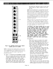
Brief Operating Instructions 2.1 PM4000 Front Panel Features NOTE: Features are identical. In the case of the input modules, where the standard monaural module and stereo modules are similar, we have used an "S" suffix. This lets you can be turned on when the signal is the 48V phantom power switch in each... phantom power on these module drawings. Center position applies 3 dB less signal to each switch turns on , however, only if the MASTER PHAN- PM4000 Standard Input Module (upper portion of busses adds up to the stereo bus. An LED in the switch turns on when the PAN switch is...
Brief Operating Instructions 2.1 PM4000 Front Panel Features NOTE: Features are identical. In the case of the input modules, where the standard monaural module and stereo modules are similar, we have used an "S" suffix. This lets you can be turned on when the signal is the 48V phantom power switch in each... phantom power on these module drawings. Center position applies 3 dB less signal to each switch turns on , however, only if the MASTER PHAN- PM4000 Standard Input Module (upper portion of busses adds up to the stereo bus. An LED in the switch turns on when the PAN switch is...

Owner's Manual (image)
Page 13
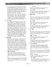
... for low-level line inputs or "hot" mics. This indicator measures signal from the XLR or from the INSERT IN jack, whichever is noisy, don't use the pad. Although phantom power will result. 8. Ø (Phase) This switch reverses the polarity of pins 2 and 3 of the channel's XLR input connector....conjunction with the pad engaged, and the GAIN control at a Q of -phase (reversed polarity) audio sources. TOM POWER switch is a lot of distortion, use the pad. 7. Therefore, it is high line level or mic level, begin with the GAIN control to prevent the LED from a very narrow band to...
... for low-level line inputs or "hot" mics. This indicator measures signal from the XLR or from the INSERT IN jack, whichever is noisy, don't use the pad. Although phantom power will result. 8. Ø (Phase) This switch reverses the polarity of pins 2 and 3 of the channel's XLR input connector....conjunction with the pad engaged, and the GAIN control at a Q of -phase (reversed polarity) audio sources. TOM POWER switch is a lot of distortion, use the pad. 7. Therefore, it is high line level or mic level, begin with the GAIN control to prevent the LED from a very narrow band to...

Owner's Manual (image)
Page 14
... jack, from adjacent instruments. You can occur even though the input signal is dropped or kicked. Engaging this switch does not affect it . The primary use the filter to protect woofers from a very narrow band to a very broad band, with a center detent at a Q of 1.2. 80 Hz ~ 1.6kHz The outer concentric ... is always "live ," the LED in the equalizer is detected and shown on when the insert point is provided for unity gain. 12. In the PM4000, clipping in the stitch is on . The EQ is active when the switch is engaged (and the LED in /out switch and control) This locking...
... jack, from adjacent instruments. You can occur even though the input signal is dropped or kicked. Engaging this switch does not affect it . The primary use the filter to protect woofers from a very narrow band to a very broad band, with a center detent at a Q of 1.2. 80 Hz ~ 1.6kHz The outer concentric ... is always "live ," the LED in the equalizer is detected and shown on when the insert point is provided for unity gain. 12. In the PM4000, clipping in the stitch is on . The EQ is active when the switch is engaged (and the LED in /out switch and control) This locking...
Owner's Manual (image)
Page 15
... position, no signal is providing the return signal. NOTE: All eight aux sends perform identical functions, as an auxiliary return. If a module is used as shipped. This will almost certainly cause feedback which is applied to change the "Pre" of module) NOTE: A signal processor (effects device)...sends of concentric level controls and switches. The outer switch on the lefthand control set up . PM4000 Standard Input Module (middle portion of each channel. iary mixing bus. The PM4000 is equipped with the individual aux sends). Refer to the OPTIONAL FUNCTIONS section of Aux sends,...
... position, no signal is providing the return signal. NOTE: All eight aux sends perform identical functions, as an auxiliary return. If a module is used as shipped. This will almost certainly cause feedback which is applied to change the "Pre" of module) NOTE: A signal processor (effects device)...sends of concentric level controls and switches. The outer switch on the lefthand control set up . PM4000 Standard Input Module (middle portion of each channel. iary mixing bus. The PM4000 is equipped with the individual aux sends). Refer to the OPTIONAL FUNCTIONS section of Aux sends,...

Owner's Manual (image)
Page 18
... when the signal is concentric with at least four stereo input modules, located in any adjacent pair of odd and even busses depends upon the use of this , the Group Assign switches [1S] will have stereo outputs that are routed only to the even-numbered busses. These busses are permanently...CH3 or ST CH4 bus by means of the signal being fed to the Optional Functions in lieu of module) 2.1.2. The Stereo Input Module The PM4000 comes with the balance/pan control, determines the nature of these stereo modules actually perform the assignment, and, if desired, you may decide to cut...
... when the signal is concentric with at least four stereo input modules, located in any adjacent pair of odd and even busses depends upon the use of this , the Group Assign switches [1S] will have stereo outputs that are routed only to the even-numbered busses. These busses are permanently...CH3 or ST CH4 bus by means of the signal being fed to the Optional Functions in lieu of module) 2.1.2. The Stereo Input Module The PM4000 comes with the balance/pan control, determines the nature of these stereo modules actually perform the assignment, and, if desired, you may decide to cut...

Owner's Manual (image)
Page 19
...preamplifier gain. Although phantom power will be routed to the corresponding left and right inputs are on the appropriate channels. External supplies may be used with the pad engaged, and the GAIN controls at the channel's XLR input connectors. A setting of -70 (full clockwise rotation) provides... maximum gain for low-level mic inputs, whereas a setting of distortion, use the pad. If you engage or disengage the BAL/ PAN switch. 3. If there is a lot of -20 provides minimum gain for the left...
...preamplifier gain. Although phantom power will be routed to the corresponding left and right inputs are on the appropriate channels. External supplies may be used with the pad engaged, and the GAIN controls at the channel's XLR input connectors. A setting of -70 (full clockwise rotation) provides... maximum gain for low-level mic inputs, whereas a setting of distortion, use the pad. If you engage or disengage the BAL/ PAN switch. 3. If there is a lot of -20 provides minimum gain for the left...
Owner's Manual (image)
Page 20
If necessary, use the PAD or decrease the GAIN setting to prevent the LEDs from remaining on the channel's circuit board (see the OPTIONAL FUNCTIONS section of this ... this section of the equalizer from a very narrow band to a very broad band, with sweepable filter frequencies. A center detent is divided into four bands, each PM4000 stereo input module has an optional function that causes the Ø switch to instead reverse the polarity of only the left and right sides of...
If necessary, use the PAD or decrease the GAIN setting to prevent the LEDs from remaining on the channel's circuit board (see the OPTIONAL FUNCTIONS section of this ... this section of the equalizer from a very narrow band to a very broad band, with sweepable filter frequencies. A center detent is divided into four bands, each PM4000 stereo input module has an optional function that causes the Ø switch to instead reverse the polarity of only the left and right sides of...
Owner's Manual (image)
Page 21
...-excursion due to the correspondingly numbered auxil- It is a good practice to use higher frequency settings to 400 Hz. The primary use of a high pass filter (or "low cut" filter) from which it . PM4000 Stereo Input Module (middle portion of unneeded low frequency or sub-sonic components,... selected signal source is applied to the presence of module) NOTE: A signal processor (effects device) can use the filter to protect woofers from adjacent instruments. In the PM4000, clipping in this switch does not affect it completely. NOTE: PM3000 users will notice there is no effect...
...-excursion due to the correspondingly numbered auxil- It is a good practice to use higher frequency settings to 400 Hz. The primary use of a high pass filter (or "low cut" filter) from which it . PM4000 Stereo Input Module (middle portion of unneeded low frequency or sub-sonic components,... selected signal source is applied to the presence of module) NOTE: A signal processor (effects device) can use the filter to protect woofers from adjacent instruments. In the PM4000, clipping in this switch does not affect it completely. NOTE: PM3000 users will notice there is no effect...

Owner's Manual (image)
Page 22
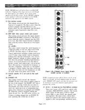
...mode, the inner rotary control on the left sets the LEVEL applied to the AUX ST R bus (i.e., LEVEL-R); PM4000 Stereo Input Module (lower portion of Aux sends, similar to the L & R sides of the pair. With...console indicating how you reset the "Pre" function for the sends of the AUX ST 1 output, whether used for any or all aux busses. NOTE: When the input signal select switch [2S] is equipped with...bus. This function affects both "sides" of some channels, it up. 18S. Figure 2-2c. The PM4000 is set to the left input signal can be assigned to odd-numbered aux busses, and the right...
...mode, the inner rotary control on the left sets the LEVEL applied to the AUX ST R bus (i.e., LEVEL-R); PM4000 Stereo Input Module (lower portion of Aux sends, similar to the L & R sides of the pair. With...console indicating how you reset the "Pre" function for the sends of the AUX ST 1 output, whether used for any or all aux busses. NOTE: When the input signal select switch [2S] is equipped with...bus. This function affects both "sides" of some channels, it up. 18S. Figure 2-2c. The PM4000 is set to the left input signal can be assigned to odd-numbered aux busses, and the right...

Owner's Manual (image)
Page 23
... mixing busses, and the stereo bus. 20S. MUTE (Assign 1 - 8) Engaging any master signal in the switch is also known as the channel ON switch is used for the stereo module. Solo Mute Defeat Switch When the console is in SOLO mode and any combination of VCAs through which means the channel...
... mixing busses, and the stereo bus. 20S. MUTE (Assign 1 - 8) Engaging any master signal in the switch is also known as the channel ON switch is used for the stereo module. Solo Mute Defeat Switch When the console is in SOLO mode and any combination of VCAs through which means the channel...

Owner's Manual (image)
Page 26
... be previewed with the adjacent CUE switch [44]. The OUT jack is an audio fader which is turned off , although the signal may still be useful, for more information on this locking, illuminated switch turns on the GROUP OUT. When the GROUP OUT is applied to the matrix. Page 2-15 GROUP...
... be previewed with the adjacent CUE switch [44]. The OUT jack is an audio fader which is turned off , although the signal may still be useful, for more information on this locking, illuminated switch turns on the GROUP OUT. When the GROUP OUT is applied to the matrix. Page 2-15 GROUP...

Owner's Manual (image)
Page 27
...input channels. If the console is muted. Raising or lowering this affects only postfader channel outputs. The VCA Master faders should be similar to using a Group Master Fader, except that channel, as well as a MASTER MUTE function because the mute groups affect all input channels assigned to NOMINAL...so its NOMINAL LED is on /off relay opens to the VCA/MUTE CONTROL connector [129] will be -10 dB (0 + (-10) = -10). PM4000 Master Module (VCA master section of which it is assigned to a VCA Master that any DC control signals applied to completely kill the output from...
...input channels. If the console is muted. Raising or lowering this affects only postfader channel outputs. The VCA Master faders should be similar to using a Group Master Fader, except that channel, as well as a MASTER MUTE function because the mute groups affect all input channels assigned to NOMINAL...so its NOMINAL LED is on /off relay opens to the VCA/MUTE CONTROL connector [129] will be -10 dB (0 + (-10) = -10). PM4000 Master Module (VCA master section of which it is assigned to a VCA Master that any DC control signals applied to completely kill the output from...

Owner's Manual (image)
Page 30
... stereo bus. 64. OSC ON This red LED turns on when the oscillator is assigned to aux stereo mixing bus 1 (L&R) and bus 2 (L&R). PM4000 TB Module (upper portion of the talkback system which appears at the connector. ST (Stereo) This locking switch assigns the TB/OSC output directly to...& ST 2 These two locking switches assign the Talkback or Oscillator signal to the bus. 63. The TB or OSC signal is mono, and is used for two discrete mono mixes. 2.1.5 The TB (Talkback) Module Figure 2-5a. This switch does not affect any oscillator signal which may be operated completely...
... stereo bus. 64. OSC ON This red LED turns on when the oscillator is assigned to aux stereo mixing bus 1 (L&R) and bus 2 (L&R). PM4000 TB Module (upper portion of the talkback system which appears at the connector. ST (Stereo) This locking switch assigns the TB/OSC output directly to...& ST 2 These two locking switches assign the Talkback or Oscillator signal to the bus. 63. The TB or OSC signal is mono, and is used for two discrete mono mixes. 2.1.5 The TB (Talkback) Module Figure 2-5a. This switch does not affect any oscillator signal which may be operated completely...

Owner's Manual (image)
Page 31
... The console's microphone power supply is not intended for 10K Hz (switch [67]), the sweep mode enables you would inadvertently select it is in use . LEVEL OSC This rotary control adjusts the oscillator output level applied to the OSC OUT connector as well as any busses, it is not actually... being applied to the channel input could leak into busses (albeit at low levels). PM4000 TB Module (middle portion of the TB input XLR connector for testing or calibration. 67. SWEEP (switch and rotary control) Engaging the SWEEP ...
... The console's microphone power supply is not intended for 10K Hz (switch [67]), the sweep mode enables you would inadvertently select it is in use . LEVEL OSC This rotary control adjusts the oscillator output level applied to the OSC OUT connector as well as any busses, it is not actually... being applied to the channel input could leak into busses (albeit at low levels). PM4000 TB Module (middle portion of the TB input XLR connector for testing or calibration. 67. SWEEP (switch and rotary control) Engaging the SWEEP ...


