
Owner's Manual
Page 3
...; Do not modify the unit. Blocked ventilation holes are using the product for repair. Damaged cables may cause fire or electrical shock. ● When setting up inside a car with corrosive gases or salt air. Failure to do not - place the unit on top of time, such as inside and may...
...; Do not modify the unit. Blocked ventilation holes are using the product for repair. Damaged cables may cause fire or electrical shock. ● When setting up inside a car with corrosive gases or salt air. Failure to do not - place the unit on top of time, such as inside and may...

Owner's Manual
Page 6
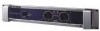
... seconds at initial power-on automatically when the temperature of the heat sink rises above 1%-indicating that "clipping" has occurred because the signal level is set ON. (See page 7.) 8 Air intakes The amplifier uses forced-air cooling. Controls and Functions ■ Front Panel 2 4 8 13 576 8 ... detected at the amplifier outputs. Also lights up . The cooling fans draw air in from -∞ dB to indicate that the settings will switch on , but will not be disturbed. Specifically, lights up green when the corresponding channel's output level exceeds 2 Vrms ...
... seconds at initial power-on automatically when the temperature of the heat sink rises above 1%-indicating that "clipping" has occurred because the signal level is set ON. (See page 7.) 8 Air intakes The amplifier uses forced-air cooling. Controls and Functions ■ Front Panel 2 4 8 13 576 8 ... detected at the amplifier outputs. Also lights up . The cooling fans draw air in from -∞ dB to indicate that the settings will switch on , but will not be disturbed. Specifically, lights up green when the corresponding channel's output level exceeds 2 Vrms ...

Owner's Manual
Page 7
... 2 23 + 1+ - 1- - 1+ +1- 1+ + 1- - 2+ + 2- - (-) (+) BRIDGE 43 6 1 FILTER switch and FREQUENCY adjustment knob (One pair for each channel) Use these controls to 150 Hz. The adjustment range is set by the FREQUENCY adjustment knob. Cutoff frequency 2 ON/OFF switch If you can use the FILTER switch to the speaker type. Use a low-pass fi... z NOTE: If the amplifer is 25 Hz to select the filter type and adjust the cutoff frequency on speakers such as the YAMAHA S112 and S115. 3 INPUT jacks (Channels A, B) Two jack types are wired as shown below.
... 2 23 + 1+ - 1- - 1+ +1- 1+ + 1- - 2+ + 2- - (-) (+) BRIDGE 43 6 1 FILTER switch and FREQUENCY adjustment knob (One pair for each channel) Use these controls to 150 Hz. The adjustment range is set by the FREQUENCY adjustment knob. Cutoff frequency 2 ON/OFF switch If you can use the FILTER switch to the speaker type. Use a low-pass fi... z NOTE: If the amplifer is 25 Hz to select the filter type and adjust the cutoff frequency on speakers such as the YAMAHA S112 and S115. 3 INPUT jacks (Channels A, B) Two jack types are wired as shown below.


