Owner's Manual
Page 2
... NOT REMOVE COVER (OR BACK). REFER SERVICING TO QUALIFIED SERVICE PERSONNEL. The wire which is coloured BLUE must be connected to qualified service personnel. The exclamation point within the product's enclosure that the connection can be connected to constitute a risk of time. 14 Refer all instructions. 5 Do not use leads or a cord that have received appropriate guidance on or pinched particularly at plugs, convenience...
... NOT REMOVE COVER (OR BACK). REFER SERVICING TO QUALIFIED SERVICE PERSONNEL. The wire which is coloured BLUE must be connected to qualified service personnel. The exclamation point within the product's enclosure that the connection can be connected to constitute a risk of time. 14 Refer all instructions. 5 Do not use leads or a cord that have received appropriate guidance on or pinched particularly at plugs, convenience...

Owner's Manual
Page 3
... a long time, make sure that receive direct sunlight. - For safe operation - Failure to this unit. Using the unit with a protective grounding connection. place the unit on a power cord covered by a carpet. ● Be sure to connect to become wet. This should be careful not to this unit. Even when the power switch is a fire hazard. ● Turn off , remove the power plug from the AC...
... a long time, make sure that receive direct sunlight. - For safe operation - Failure to this unit. Using the unit with a protective grounding connection. place the unit on a power cord covered by a carpet. ● Be sure to connect to become wet. This should be careful not to this unit. Even when the power switch is a fire hazard. ● Turn off , remove the power plug from the AC...
Owner's Manual
Page 4
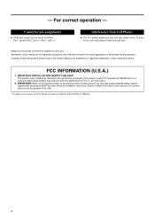
... follows Pin 1: ground; Follow all installation instructions. For correct operation - Interference from the unit. Always turn the power off when the amplifier is not in use this product MUST be used in this Owner's Manual are wired as indicated in the instructions contained in this unit may induce noise. IMPORTANT: When connecting this manual are for explanatory purposes only, and may...
... follows Pin 1: ground; Follow all installation instructions. For correct operation - Interference from the unit. Always turn the power off when the amplifier is not in use this product MUST be used in this Owner's Manual are wired as indicated in the instructions contained in this unit may induce noise. IMPORTANT: When connecting this manual are for explanatory purposes only, and may...

Owner's Manual
Page 5
... reliability. This Owner's Manual covers the four models: P7000S, P5000S, P3500S and P2500S power amplifiers. Contents Controls and Functions 6 Front Panel 6 Rear Panel 7 Speaker Connections 9 Speaker impedance 9 Wiring 10 Rack Mounting 11 Specifications 12 General Specifications 12 Block Diagram 13 Dimensions 14 Current Draw 14 Troubleshooting 15 5 Features • With two types of input jacks (balanced XLR and balanced phone) and three types of output jacks (Speakon...
... reliability. This Owner's Manual covers the four models: P7000S, P5000S, P3500S and P2500S power amplifiers. Contents Controls and Functions 6 Front Panel 6 Rear Panel 7 Speaker Connections 9 Speaker impedance 9 Wiring 10 Rack Mounting 11 Specifications 12 General Specifications 12 Block Diagram 13 Dimensions 14 Current Draw 14 Troubleshooting 15 5 Features • With two types of input jacks (balanced XLR and balanced phone) and three types of output jacks (Speakon...

Owner's Manual
Page 6
... at the amplifier outputs. NOTE: If you wish to lock in the knob settings, you do not come on at initial power-on or off and normal operation resumes. 4 CLIP indicator Lights up red when the output signal distortion on the rear panel is detected at time of screw holes. Controls and Functions ■ Front Panel 2 4 8 13 576 8 1 POWER switch and indicator Press to...
... at the amplifier outputs. NOTE: If you wish to lock in the knob settings, you do not come on at initial power-on or off and normal operation resumes. 4 CLIP indicator Lights up red when the output signal distortion on the rear panel is detected at time of screw holes. Controls and Functions ■ Front Panel 2 4 8 13 576 8 1 POWER switch and indicator Press to...

Owner's Manual
Page 7
... switch to adjust the cutoff frequency. If you select SUBWOOFER or LOW CUT, you set to enhance speaker output. You use any filter. SUBWOOFER..... hot 21 ground 3 cold • Phone jack Phone jacks are wired as to BRIDGE mode, only the switch and knob for Channel A are effective. (The Channel B frequency controls are provided for each channel) Use these controls to OFF. The results (the actual change in the low-frequency balance) will vary accord- Use a low...
... switch to adjust the cutoff frequency. If you select SUBWOOFER or LOW CUT, you set to enhance speaker output. You use any filter. SUBWOOFER..... hot 21 ground 3 cold • Phone jack Phone jacks are wired as to BRIDGE mode, only the switch and knob for Channel A are effective. (The Channel B frequency controls are provided for each channel) Use these controls to OFF. The results (the actual change in the low-frequency balance) will vary accord- Use a low...

Owner's Manual
Page 8
...Channel A input signal is a screw-type ground terminal. To adjust the volume, you are having a problem with a conventional stereo amplifier). Channel A and B volumes can be independently adjusted. • BRIDGE mode The Channel A input signal is output from the BRIDGE output jacks. 4 STEREO/PARALLEL/BRIDGE switch Use this switch to select the operating mode. • STEREO mode Channels A and B operate independently (as with hum or noise, use the Channel A volume control knob. 5 SPEAKER jacks Neutrik NL4FC Speakon output connectors, 5-way binding post output jacks, Phone output...
...Channel A input signal is a screw-type ground terminal. To adjust the volume, you are having a problem with a conventional stereo amplifier). Channel A and B volumes can be independently adjusted. • BRIDGE mode The Channel A input signal is output from the BRIDGE output jacks. 4 STEREO/PARALLEL/BRIDGE switch Use this switch to select the operating mode. • STEREO mode Channels A and B operate independently (as with hum or noise, use the Channel A volume control knob. 5 SPEAKER jacks Neutrik NL4FC Speakon output connectors, 5-way binding post output jacks, Phone output...
Owner's Manual
Page 9
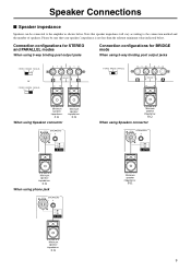
... using phone jack LOCK LOCK SPEAKERS 3 2 23 + 1+ - 1- 1+ + 1- - 2+ + 2- - Minimum speaker impedance: 4 Ω When using Speakon connector LOCK LOCK SPEAKERS 3 2 23 + 1+ - 1- 1+ + 1- - 2+ + 2- - Please be connected to the connection method and the number of speakers. Note that your speakers' impedance is not less than the relevant minimum value indicated below . Connection configurations for STEREO and PARALLEL modes When using 5-way binding post output jacks Connection configurations for BRIDGE mode When using 5-way binding post output jacks STEREO...
... using phone jack LOCK LOCK SPEAKERS 3 2 23 + 1+ - 1- 1+ + 1- - 2+ + 2- - Minimum speaker impedance: 4 Ω When using Speakon connector LOCK LOCK SPEAKERS 3 2 23 + 1+ - 1- 1+ + 1- - 2+ + 2- - Please be connected to the connection method and the number of speakers. Note that your speakers' impedance is not less than the relevant minimum value indicated below . Connection configurations for STEREO and PARALLEL modes When using 5-way binding post output jacks Connection configurations for BRIDGE mode When using 5-way binding post output jacks STEREO...

Owner's Manual
Page 10
...;er. Speakon connector (1) Turn off the POWER switch. (2) Remove the cover attachment screws and remove the pro- Tighten the terminals to securely clamp the wires. Bare wire Chassis (4) Reattach the protective cover over the speaker terminals. 10 Neutrik NL4FC plugs CHANNEL A STEREO or PARALLEL BRIDGE 1+ A+ 1+ + 1- B- 2- 15mm ■ Wiring 5-way binding post (1) Turn off the POWER switch. (2) Insert the Neutrik NL4FC plugs into the jack on the rear of the ampli...
...;er. Speakon connector (1) Turn off the POWER switch. (2) Remove the cover attachment screws and remove the pro- Tighten the terminals to securely clamp the wires. Bare wire Chassis (4) Reattach the protective cover over the speaker terminals. 10 Neutrik NL4FC plugs CHANNEL A STEREO or PARALLEL BRIDGE 1+ A+ 1+ + 1- B- 2- 15mm ■ Wiring 5-way binding post (1) Turn off the POWER switch. (2) Insert the Neutrik NL4FC plugs into the jack on the rear of the ampli...

Owner's Manual
Page 11
... open -backed rack, and when mounting any number of each amplifier, as shown below. 11 Note: EIA stands for Electronic Industries Alliance. Ventilation panel(s) Use 1U-size blank panel(s). 480 44 Unit: mm If mounting up to install ventilation panel(s) as shown below. Rack Mounting Mounting in a standard EIA rack If you are mounting multiple power...
... open -backed rack, and when mounting any number of each amplifier, as shown below. 11 Note: EIA stands for Electronic Industries Alliance. Ventilation panel(s) Use 1U-size blank panel(s). 480 44 Unit: mm If mounting up to install ventilation panel(s) as shown below. Rack Mounting Mounting in a standard EIA rack If you are mounting multiple power...

Owner's Manual
Page 12
Yamaha Corp. max.) 32.1 dB Input Impedance 30 kΩ/balanced, 15 kΩ/unbalanced Controls Front Panel POWER switch (Push on/Push off) Two 31-step Volume control knobs (one per ch) Rear Panel MODE switch (STEREO/PARALLEL/BRIDGE) Two FILTER switches (SUBWOOFER/LOW CUT/OFF) Two fc knobs (25 to change or modify products or specifications at any time without prior notice. min. 20 Hz - 20...
Yamaha Corp. max.) 32.1 dB Input Impedance 30 kΩ/balanced, 15 kΩ/unbalanced Controls Front Panel POWER switch (Push on/Push off) Two 31-step Volume control knobs (one per ch) Rear Panel MODE switch (STEREO/PARALLEL/BRIDGE) Two FILTER switches (SUBWOOFER/LOW CUT/OFF) Two fc knobs (25 to change or modify products or specifications at any time without prior notice. min. 20 Hz - 20...

Owner's Manual
Page 14
■ Dimensions ■ Current Draw P7000S standby idle 1/8 power 8Ω/ch 4Ω/ch 1/3 power 8Ω/ch 4Ω/ch P5000S standby idle 1/8 power 8Ω/ch 4Ω/ch 1/3 power 8Ω/ch 4Ω/ch P3500S standby idle 1/8 power 8Ω/ch 4Ω/ch 1/3 power 8Ω/ch 4Ω/ch Line Current (A) 100/120V 230/240V 0.08 0.04 1.0 0.5 5.4 3.0 8.5 4.7 12.8 7.0 20.6 11.3 Line Current (A) 100/120V 230/240V...
■ Dimensions ■ Current Draw P7000S standby idle 1/8 power 8Ω/ch 4Ω/ch 1/3 power 8Ω/ch 4Ω/ch P5000S standby idle 1/8 power 8Ω/ch 4Ω/ch 1/3 power 8Ω/ch 4Ω/ch P3500S standby idle 1/8 power 8Ω/ch 4Ω/ch 1/3 power 8Ω/ch 4Ω/ch Line Current (A) 100/120V 230/240V 0.08 0.04 1.0 0.5 5.4 3.0 8.5 4.7 12.8 7.0 20.6 11.3 Line Current (A) 100/120V 230/240V...

Owner's Manual
Page 15
... take appropriate measures to protect the power transistors. Consult your dealer or the nearest Yamaha service center. PROTECTION indicator lights. The amplifier load is a short at least 4 Ω (STEREO/PARALLEL mode) or 8 Ω (BRIDGE mode). The thermal protection circuit operates to improve the airflow around the amplifier. Use a speaker system with an impedance of program material with extremely heavy...
... take appropriate measures to protect the power transistors. Consult your dealer or the nearest Yamaha service center. PROTECTION indicator lights. The amplifier load is a short at least 4 Ω (STEREO/PARALLEL mode) or 8 Ω (BRIDGE mode). The thermal protection circuit operates to improve the airflow around the amplifier. Use a speaker system with an impedance of program material with extremely heavy...

Owner's Manual
Page 16
...-2441 Yamaha Pro Audio global web site http://www.yamahaproaudio.com/ Yamaha Manual Library http://www.yamaha.co.jp/manual/ U.R.G., Pro Audio & Digital Musical Instrument Division, Yamaha Corporation © 2003 Yamaha Corporation ...TURKEY/CYPRUS Yamaha Music Europe GmbH Siemensstraße 22-34, 25462 Rellingen, Germany Tel: 04101-3030 OTHER COUNTRIES Yamaha Music Gulf FZE LOB 16-513, P.O.Box 17328,...Yamaha Music Asia Pte., Ltd. #03-11 A-Z Building 140 Paya Lebor Road, Singapore 409015 Tel: 747-4374 TAIWAN Yamaha KHS Music Co., Ltd. 3F, #6, Sec.2, Nan Jing E. Nusantik Gedung Yamaha Music Center...
...-2441 Yamaha Pro Audio global web site http://www.yamahaproaudio.com/ Yamaha Manual Library http://www.yamaha.co.jp/manual/ U.R.G., Pro Audio & Digital Musical Instrument Division, Yamaha Corporation © 2003 Yamaha Corporation ...TURKEY/CYPRUS Yamaha Music Europe GmbH Siemensstraße 22-34, 25462 Rellingen, Germany Tel: 04101-3030 OTHER COUNTRIES Yamaha Music Gulf FZE LOB 16-513, P.O.Box 17328,...Yamaha Music Asia Pte., Ltd. #03-11 A-Z Building 140 Paya Lebor Road, Singapore 409015 Tel: 747-4374 TAIWAN Yamaha KHS Music Co., Ltd. 3F, #6, Sec.2, Nan Jing E. Nusantik Gedung Yamaha Music Center...


