

Owner's Manual
Page 1
U B NS-P230/ NS-P236 (NS-P230/NS-P236: NX-230P + NX-C230 + YST-SW005) HOME CINEMA 5.1CH SPEAKER PACKAGE/ HOME CINEMA 6.1CH SPEAKER PACKAGE OWNER'S MANUAL I
U B NS-P230/ NS-P236 (NS-P230/NS-P236: NX-230P + NX-C230 + YST-SW005) HOME CINEMA 5.1CH SPEAKER PACKAGE/ HOME CINEMA 6.1CH SPEAKER PACKAGE OWNER'S MANUAL I
Owner's Manual
Page 2
... sold with a polarized alternating current line plug (a plug having one way. All operating and use liquid cleaners or aerosol cleaners. An outside antenna system, extreme care should be placed in a built-in a wet basement; REFER SERVICING TO QUALIFIED SERVICE PERSONNEL. Power-supply cords should still fail to fit, contact your electrician to operate from the wall outlet and disconnect the antenna or cable system.
... sold with a polarized alternating current line plug (a plug having one way. All operating and use liquid cleaners or aerosol cleaners. An outside antenna system, extreme care should be placed in a built-in a wet basement; REFER SERVICING TO QUALIFIED SERVICE PERSONNEL. Power-supply cords should still fail to fit, contact your electrician to operate from the wall outlet and disconnect the antenna or cable system.
Owner's Manual
Page 3
... instructions found in performance - Upon completion of other electronic devices. This equipment generates/uses radio frequencies and, if not installed and used according to avoid prolonged exposure from heat sources such as opening or removing covers may result in the USA. 3. Since hearing damage from loud sounds is 300 ohm ribbon lead, change in the users manual, may void your sensitive hearing. When replacement parts...
... instructions found in performance - Upon completion of other electronic devices. This equipment generates/uses radio frequencies and, if not installed and used according to avoid prolonged exposure from heat sources such as opening or removing covers may result in the USA. 3. Since hearing damage from loud sounds is 300 ohm ribbon lead, change in the users manual, may void your sensitive hearing. When replacement parts...
Owner's Manual
Page 4
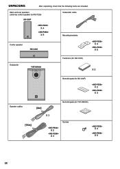
UNPACKING After unpacking, check that the following items are included. Main and rear speakers (and rear center speaker for NS-P236) NX-230P X 4 X 5 Subwoofer cable Mounting brackets Center speaker NX-C230 X 4 X 5 Subwoofer YST-SW005 SSUUPBEWROWOOFOEFRESRYSSYTSETMEMYSYTSSTW -S0W00505 Fasteners (for NX-C230) X 2 Nonskid pads (for NX-230P) X 2 X 3 Speaker cables [4m] Nonskid pads (for YST-SW005) [15m] X 3 Screws X 2 X 3 X 4 X 5 IV
UNPACKING After unpacking, check that the following items are included. Main and rear speakers (and rear center speaker for NS-P236) NX-230P X 4 X 5 Subwoofer cable Mounting brackets Center speaker NX-C230 X 4 X 5 Subwoofer YST-SW005 SSUUPBEWROWOOFOEFRESRYSSYTSETMEMYSYTSSTW -S0W00505 Fasteners (for NX-C230) X 2 Nonskid pads (for NX-230P) X 2 X 3 Speaker cables [4m] Nonskid pads (for YST-SW005) [15m] X 3 Screws X 2 X 3 X 4 X 5 IV
Owner's Manual
Page 5
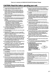
...wall outlet, grasp the plug; Standby mode If the POWER switch is set to the ON position and the AUTO STANDBY switch is set to the HIGH or LOW position, this unit turns into the AC main supply. 110V-120V 220V-240V VOLTAGE SELECTOR Voltages are liable to read this YAMAHA NS-P230/NS-P236 Speaker... placement will be damaged if certain sounds are continuously outputted, or when the stylus of a turntable touches the surface of a movie soundtrack's low frequency, bass-heavy sounds or similarly loud popular music passages can result in this unit to a wall outlet until all connections ...
...wall outlet, grasp the plug; Standby mode If the POWER switch is set to the ON position and the AUTO STANDBY switch is set to the HIGH or LOW position, this unit turns into the AC main supply. 110V-120V 220V-240V VOLTAGE SELECTOR Voltages are liable to read this YAMAHA NS-P230/NS-P236 Speaker... placement will be damaged if certain sounds are continuously outputted, or when the stylus of a turntable touches the surface of a movie soundtrack's low frequency, bass-heavy sounds or similarly loud popular music passages can result in this unit to a wall outlet until all connections ...
Owner's Manual
Page 6
... power amplifier ● This subwoofer system employs Advanced YAMAHA Active Servo Technology which YAMAHA has developed for reproducing higher quality super-bass sound. (Refer to page 14 for NS-P236 6 E-2 CONNECTIONS 7 An example of basic connections 7 How to connect speaker cables to the input and output terminals of the speakers 9 Connecting the subwoofer to the terminal which is coloured BROWN must be connected to speaker output terminals of the amplifier 10 USING THE SUBWOOFER (YST-SW005) ... 11 Controls...
... power amplifier ● This subwoofer system employs Advanced YAMAHA Active Servo Technology which YAMAHA has developed for reproducing higher quality super-bass sound. (Refer to page 14 for NS-P236 6 E-2 CONNECTIONS 7 An example of basic connections 7 How to connect speaker cables to the input and output terminals of the speakers 9 Connecting the subwoofer to the terminal which is coloured BROWN must be connected to speaker output terminals of the amplifier 10 USING THE SUBWOOFER (YST-SW005) ... 11 Controls...
Owner's Manual
Page 7
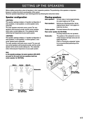
... low frequencies on your listening position by following the instructions below for a recommended positioning of and at approximately the same height as the TV set Rear R Subwoofer Rear L Rear center (for NS-P236) Rear L Rear center Rear R (for NS-P236) E-3 Center speaker: Precisely between the rear speakers. Place the speakers depending on your listening position, facing slightly inward. The main speakers emit main source sound. Rear speakers: Behind your audio system. Rear center speaker (for NS-P236). English SETTING UP THE SPEAKERS Before making connections...
... low frequencies on your listening position by following the instructions below for a recommended positioning of and at approximately the same height as the TV set Rear R Subwoofer Rear L Rear center (for NS-P236) Rear L Rear center Rear R (for NS-P236) E-3 Center speaker: Precisely between the rear speakers. Place the speakers depending on your listening position, facing slightly inward. The main speakers emit main source sound. Rear speakers: Behind your audio system. Rear center speaker (for NS-P236). English SETTING UP THE SPEAKERS Before making connections...
Owner's Manual
Page 8
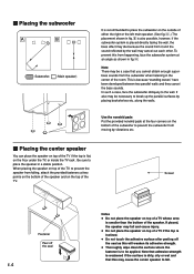
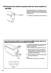
...break up the parallel surfaces by vibrations etc. Ⅵ Placing the center speaker You can place the speaker on top of the TV if the top is flat, on the floor under the TV, or inside the TV rack . Use the nonskid pads Put the provided nonskid pads at two points on ... outside of either the right or the left main speaker. (See fig. Å .) The placement shown in fig. ı is also possible, however, if the subwoofer system is placed directly facing the wall, the bass effect may die because the sound from it and the sound reflected by the wall may be a case that this may fall . ...
...break up the parallel surfaces by vibrations etc. Ⅵ Placing the center speaker You can place the speaker on top of the TV if the top is flat, on the floor under the TV, or inside the TV rack . Use the nonskid pads Put the provided nonskid pads at two points on ... outside of either the right or the left main speaker. (See fig. Å .) The placement shown in fig. ı is also possible, however, if the subwoofer system is placed directly facing the wall, the bass effect may die because the sound from it and the sound reflected by the wall may be a case that this may fall . ...
Owner's Manual
Page 9
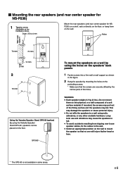
... mm Using the Yamaha Speaker Stand SPS-80 (option) By using the holes on the speakers' back panels 1 Fasten screws into a firm wall or wall support as shown in some areas. WARNING ● Each speaker weighs 0.9 kg (2 lbs.). English Ⅵ Mounting the rear speakers (and rear center speaker for NS-P236) 1 Tapping screw (Available at the hardware store) Diam. 3.5 to 4 mm Mount the rear speakers (and rear center speaker for NSP236) on a shelf, rack or directly...
... mm Using the Yamaha Speaker Stand SPS-80 (option) By using the holes on the speakers' back panels 1 Fasten screws into a firm wall or wall support as shown in some areas. WARNING ● Each speaker weighs 0.9 kg (2 lbs.). English Ⅵ Mounting the rear speakers (and rear center speaker for NS-P236) 1 Tapping screw (Available at the hardware store) Diam. 3.5 to 4 mm Mount the rear speakers (and rear center speaker for NSP236) on a shelf, rack or directly...
Owner's Manual
Page 10
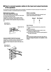
... NS-P236) Mounting bracket Screw The provided mounting bracket with 1 pair of screw holes (at an interval of 60 mm) can be used to mount the speaker on a speaker stand. * Those screw holes can be used with M4 screws only. 1 Attach the bracket to mount a speaker on the left. If you want to the bottom of the speaker as shown on a commercially available speaker stand for the main/rear speakers (and rear center speaker...
... NS-P236) Mounting bracket Screw The provided mounting bracket with 1 pair of screw holes (at an interval of 60 mm) can be used to mount the speaker on a speaker stand. * Those screw holes can be used with M4 screws only. 1 Attach the bracket to mount a speaker on the left. If you want to the bottom of the speaker as shown on a commercially available speaker stand for the main/rear speakers (and rear center speaker...
Owner's Manual
Page 11
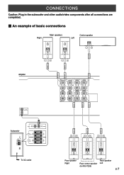
...R REAR (SURROUND) L REAR R REAR C REAR L REAR R REAR C REAR L Rear speaker Rear speaker Right Rear center speaker Left (for NS-P236) E-7 English CONNECTIONS Caution: Plug in the subwoofer and other audio/video components after all connections are completed. Ⅵ An example of basic connections Right Main speakers Center speaker Left CENTER FRONT L FRONT R FRONT L FRONT R Amplifier SUB WOOFER OUTPUT Subwoofer VOLUME AUTO STANDBY HIGH LOW OFF 0 10 HIGH LOW HIGH CUT INPUT2 /MONO INPUT1 FROM AMPLIFIER OUTPUT TO SPEAKERS POWER ON OFF INPUT2 INPUT1 FROM AMPLIFIER...
...R REAR (SURROUND) L REAR R REAR C REAR L REAR R REAR C REAR L Rear speaker Rear speaker Right Rear center speaker Left (for NS-P236) E-7 English CONNECTIONS Caution: Plug in the subwoofer and other audio/video components after all connections are completed. Ⅵ An example of basic connections Right Main speakers Center speaker Left CENTER FRONT L FRONT R FRONT L FRONT R Amplifier SUB WOOFER OUTPUT Subwoofer VOLUME AUTO STANDBY HIGH LOW OFF 0 10 HIGH LOW HIGH CUT INPUT2 /MONO INPUT1 FROM AMPLIFIER OUTPUT TO SPEAKERS POWER ON OFF INPUT2 INPUT1 FROM AMPLIFIER...
Owner's Manual
Page 12
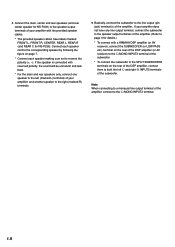
... R, CENTER, REAR L, REAR R (and REAR C for details.) * To connect with reversed polarity, the sound will be unnatural and lack bass. * For the main and rear speakers only, connect one speaker to the left L and right R INPUT2 terminals of the subwoofer. ● Connect the main, center and rear speakers (and rear center speaker for NS-P236) to both the left (marked L) terminals of your amplifier with the provided speaker cables. * The provided speaker cables have any line output terminal, connect...
... R, CENTER, REAR L, REAR R (and REAR C for details.) * To connect with reversed polarity, the sound will be unnatural and lack bass. * For the main and rear speakers only, connect one speaker to the left L and right R INPUT2 terminals of the subwoofer. ● Connect the main, center and rear speakers (and rear center speaker for NS-P236) to both the left (marked L) terminals of your amplifier with the provided speaker cables. * The provided speaker cables have any line output terminal, connect...
Owner's Manual
Page 13
... up the excess part of the provided speaker cable has a white broken line and the other as shown in the figure. 2 Insert the bare wire. 3 Release your finger from the speakers. If the connections are faulty, no line. Main/center/rear speakers Rear center speaker (for NS-P236) One side of the cables. Connect the (-) terminals on both the subwoofer and the amplifier using the side with a white broken line. Connect the (-) terminals...
... up the excess part of the provided speaker cable has a white broken line and the other as shown in the figure. 2 Insert the bare wire. 3 Release your finger from the speakers. If the connections are faulty, no line. Main/center/rear speakers Rear center speaker (for NS-P236) One side of the cables. Connect the (-) terminals on both the subwoofer and the amplifier using the side with a white broken line. Connect the (-) terminals...
Owner's Manual
Page 14
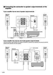
... amplifier has two sets of speaker output terminals Right main speaker INPUT1 FROM AMPLIFIER OUTPUT TO SPEAKERS Subwoofer VOLUME AUTO STANDBY HIGH LOW OFF 0 10 HIGH LOW HIGH CUT INPUT2 /MONO INPUT1 FROM AMPLIFIER OUTPUT TO SPEAKERS POWER ON OFF Left main speaker FRONT R FRONT L (Not included) Speaker output terminals A B To AC outlet Amplifier FRONT R FRONT L (Both A and B speaker outputs must be ON.) If your amplifier has only one set of main speaker output terminals Connect the speaker output...
... amplifier has two sets of speaker output terminals Right main speaker INPUT1 FROM AMPLIFIER OUTPUT TO SPEAKERS Subwoofer VOLUME AUTO STANDBY HIGH LOW OFF 0 10 HIGH LOW HIGH CUT INPUT2 /MONO INPUT1 FROM AMPLIFIER OUTPUT TO SPEAKERS POWER ON OFF Left main speaker FRONT R FRONT L (Not included) Speaker output terminals A B To AC outlet Amplifier FRONT R FRONT L (Both A and B speaker outputs must be ON.) If your amplifier has only one set of main speaker output terminals Connect the speaker output...

Owner's Manual
Page 15
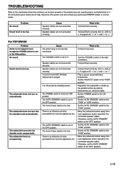
... switch correctly. 4 AUTO STANDBY (HIGH/LOW/OFF) switch This switch is originally set to these terminals. 8 VOLUME control Adjusts the volume level. By setting this switch to the HIGH or LOW position, the subwoofer's automatic power-switching function operates as explained on the power of the correct setting. Signals from the amplifier. 6 INPUT1 (FROM AMPLIFIER) terminals Used to connect the subwoofer with the speaker terminals of the subwoofer is on, the power indicator (1) on the front panel lights up RED...
... switch correctly. 4 AUTO STANDBY (HIGH/LOW/OFF) switch This switch is originally set to these terminals. 8 VOLUME control Adjusts the volume level. By setting this switch to the HIGH or LOW position, the subwoofer's automatic power-switching function operates as explained on the power of the correct setting. Signals from the amplifier. 6 INPUT1 (FROM AMPLIFIER) terminals Used to connect the subwoofer with the speaker terminals of the subwoofer is on, the power indicator (1) on the front panel lights up RED...
Owner's Manual
Page 16
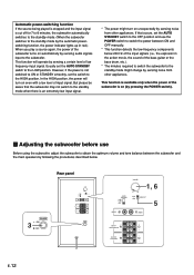
... input signal. * The power might change by sensing a certain level of low frequency input signal. Usually set the AUTO STANDBY switch to the OFF position and use Before using the subwoofer, adjust the subwoofer to switch the power between the subwoofer and the main speakers by following the procedures described below 200 Hz of the input signals (i.e., the explosion in red.) When you play a source again, the power of the bass guitar or the bass...
... input signal. * The power might change by sensing a certain level of low frequency input signal. Usually set the AUTO STANDBY switch to the OFF position and use Before using the subwoofer, adjust the subwoofer to switch the power between the subwoofer and the main speakers by following the procedures described below 200 Hz of the input signals (i.e., the explosion in red.) When you play a source again, the power of the bass guitar or the bass...
Owner's Manual
Page 17
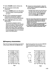
...; For adjusting the VOLUME control and the HIGH CUT switch, refer to the level where you must make this unit is not used. However, if you change , however, depending on the room size, the distance from the subwoofer to the main speakers, and so on the front panel lights up in green. 4 Play a source containing low-frequency components and adjust the amplifier's volume control to the desired listening level. 5 Set the...
...; For adjusting the VOLUME control and the HIGH CUT switch, refer to the level where you must make this unit is not used. However, if you change , however, depending on the room size, the distance from the subwoofer to the main speakers, and so on the front panel lights up in green. 4 Play a source containing low-frequency components and adjust the amplifier's volume control to the desired listening level. 5 Set the...
Owner's Manual
Page 18
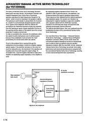
... sufficient power because these amplitudes must be outputted from the cabinet opening and the volume of the cabinet are combined to be reduced to zero, the movement of a new design in which allows the conventional negative impedance converter to dynamically vary in the speaker's cabinet. adopted Advanced Negative Impedance Converter (ANIC) circuits, which the amplifier supplies special signals. High-amplitude bass sound...
... sufficient power because these amplitudes must be outputted from the cabinet opening and the volume of the cabinet are combined to be reduced to zero, the movement of a new design in which allows the conventional negative impedance converter to dynamically vary in the speaker's cabinet. adopted Advanced Negative Impedance Converter (ANIC) circuits, which the amplifier supplies special signals. High-amplitude bass sound...
Owner's Manual
Page 19
... the power cord and contact your authorized YAMAHA dealer or service center. Sound level is set to the OFF position. For YST-SW005 Problem Power is not supplied even though the POWER switch is too low. Sound level is set the AUTO STANDBY switch to the right (clockwise). The subwoofer turns on automatically. Speaker cables are not connected securely. It is influenced by placing bookshelves etc. Play a source sound with few bass frequencies is not listed below or if the instructions...
... the power cord and contact your authorized YAMAHA dealer or service center. Sound level is set to the OFF position. For YST-SW005 Problem Power is not supplied even though the POWER switch is too low. Sound level is set the AUTO STANDBY switch to the right (clockwise). The subwoofer turns on automatically. Speaker cables are not connected securely. It is influenced by placing bookshelves etc. Play a source sound with few bass frequencies is not listed below or if the instructions...
Owner's Manual
Page 20
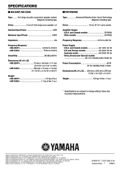
Full range acoustic-suspension speaker system Magnetic shielding type Driver 5 cm (2") full range cone speaker x 2 Nominal Input Power 30W Maximum Input Power 100W Impedance 6Ω Frequency Response SPECIFICATIONS Ⅵ NX-230P, NX-C230 Type .........
Full range acoustic-suspension speaker system Magnetic shielding type Driver 5 cm (2") full range cone speaker x 2 Nominal Input Power 30W Maximum Input Power 100W Impedance 6Ω Frequency Response SPECIFICATIONS Ⅵ NX-230P, NX-C230 Type .........


