

Owner's Manual
Page 1
... 10 AUX 3 0 10 AUX 3 0 10 AUX 3 0 10 AUX 3 0 10 AUX 3 0 10 AUX 3 0 10 AUX 3 0 10 AUX 3 0 10 AUX 3 0 10 AUX 3 0 10 AUX 3 0 10 AUX 3 0 10 AUX 3 0 10 AUX 3 0 10 AUX 3 0 10 AUX 3 0 10 AUX 3 0 10 AUX 3 0 10 AUX 3 0 10 AUX 3 0 10 AUX 3 0 10 AUX 3 0 10 AUX 3 -15 +15 HIGH -15 +15 HIGH MIXING CONSOLE PEAK +6 +4 +2 0 -2 -4 -7 -10 -15 -20 GROUP 1 GROUP 2 PEAK +6 +4 +2 0 -2 -4 -7 -10 -15 -20 GROUP 3 GROUP 4 L ST2/MONITOR R METER SELECT PEAK +6 +4 +2 0 -2 -4 -7 -10 -15 -20 L STEREO 1 R POWER PHANTOM 10...
... 10 AUX 3 0 10 AUX 3 0 10 AUX 3 0 10 AUX 3 0 10 AUX 3 0 10 AUX 3 0 10 AUX 3 0 10 AUX 3 0 10 AUX 3 0 10 AUX 3 0 10 AUX 3 0 10 AUX 3 0 10 AUX 3 0 10 AUX 3 0 10 AUX 3 0 10 AUX 3 0 10 AUX 3 0 10 AUX 3 0 10 AUX 3 0 10 AUX 3 0 10 AUX 3 0 10 AUX 3 0 10 AUX 3 -15 +15 HIGH -15 +15 HIGH MIXING CONSOLE PEAK +6 +4 +2 0 -2 -4 -7 -10 -15 -20 GROUP 1 GROUP 2 PEAK +6 +4 +2 0 -2 -4 -7 -10 -15 -20 GROUP 3 GROUP 4 L ST2/MONITOR R METER SELECT PEAK +6 +4 +2 0 -2 -4 -7 -10 -15 -20 L STEREO 1 R POWER PHANTOM 10...
Owner's Manual
Page 3
KEMBLE MUSIC (U.K.) LTD. 5-2 BS2 01 2/5 MX400 User's Guide Contents i Contents 1 Introduction 1 Features of the MX400 1 2 Front and rear panels 2 Input modules 2 Stereo module 5 AUX SEND module 7 GROUP module 7 ST2/MONITOR module 8 Master module (L-ST1-R 9 Meters 10 3 Rear panel 11 4 Appendix 14 General specifications 14 Input Specifications 15 Output Specifications 16 Dimensions 16 IMPORTANT NOTICE FOR THE UNITED KINGDOM Connecting the Plug and Cord IMPORTANT: The wires in this mains lead are coloured in accordance with the following code: BLUE...
KEMBLE MUSIC (U.K.) LTD. 5-2 BS2 01 2/5 MX400 User's Guide Contents i Contents 1 Introduction 1 Features of the MX400 1 2 Front and rear panels 2 Input modules 2 Stereo module 5 AUX SEND module 7 GROUP module 7 ST2/MONITOR module 8 Master module (L-ST1-R 9 Meters 10 3 Rear panel 11 4 Appendix 14 General specifications 14 Input Specifications 15 Output Specifications 16 Dimensions 16 IMPORTANT NOTICE FOR THE UNITED KINGDOM Connecting the Plug and Cord IMPORTANT: The wires in this mains lead are coloured in accordance with the following code: BLUE...
Owner's Manual
Page 4
... Yamaha service personnel. MX400 User's Guide Opening the case and/or tampering with care. 4. including the AC power cord - by gripping the connector, not the cord. 7. ii Precautions Precautions 1. Do Not Open the Case or Attempt Repairs or Modifications Yourself This product contains no user-serviceable parts. Refer all equipment used in your local AC mains supply. Always power off before making connections Always turn the power...
... Yamaha service personnel. MX400 User's Guide Opening the case and/or tampering with care. 4. including the AC power cord - by gripping the connector, not the cord. 7. ii Precautions Precautions 1. Do Not Open the Case or Attempt Repairs or Modifications Yourself This product contains no user-serviceable parts. Refer all equipment used in your local AC mains supply. Always power off before making connections Always turn the power...
Owner's Manual
Page 5
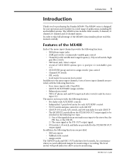
... for monitoring or recording. MX400 User's Guide In order to be switched in a wide range of the MX400's functionality, please read this manual carefully. The level meters with 2 band EQ • GROUP/AUX/STEREO assign switches • Balance/pan control • TRS 1/4" phone jack and RCA input jack select switch (only for stereo input 1/2) The master section provides the following features. • Five fader-style AUX SEND controls • Independent 3 point level meter for each AUX SEND control • TO ST switch and pan control...
... for monitoring or recording. MX400 User's Guide In order to be switched in a wide range of the MX400's functionality, please read this manual carefully. The level meters with 2 band EQ • GROUP/AUX/STEREO assign switches • Balance/pan control • TRS 1/4" phone jack and RCA input jack select switch (only for stereo input 1/2) The master section provides the following features. • Five fader-style AUX SEND controls • Independent 3 point level meter for each AUX SEND control • TO ST switch and pan control...
Owner's Manual
Page 6
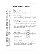
... being input. If the PEAK indicator lights frequently, lower the GAIN control to an appropriate level. Set the signal level based on -16 GAIN -60 4 SIGNAL indicator and PEAK indicator When the post EQ signal level (nominal level 0dB) reaches -10dB, the SIGNAL indicator will light. MX400 User's Guide Signal source GAIN control position 20dB pad switch Dynamic mic (low level) -60 ~ -50 off -16 GAIN -60 Condenser mic (high level) -35 off -16 GAIN -60 Audio device, electronic musical instrument (low level...
... being input. If the PEAK indicator lights frequently, lower the GAIN control to an appropriate level. Set the signal level based on -16 GAIN -60 4 SIGNAL indicator and PEAK indicator When the post EQ signal level (nominal level 0dB) reaches -10dB, the SIGNAL indicator will light. MX400 User's Guide Signal source GAIN control position 20dB pad switch Dynamic mic (low level) -60 ~ -50 off -16 GAIN -60 Condenser mic (high level) -35 off -16 GAIN -60 Audio device, electronic musical instrument (low level...
Owner's Manual
Page 7
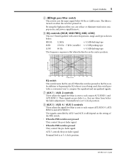
.... MX400 User's Guide Input modules 3 5 80 high pass filter switch This switch cuts the input signal below . HIGH: 12 kHz +/-15dB shelving type MID: 250 Hz ~ 5 kHz (variable) +/-15dB peaking type LOW: 80 Hz +/-15dB shelving type The frequency response is pressed in . AUX 5 controls the post-fader signal. By using the high pass filter, you can reduce or eliminate wind noise, mic pop noise...
.... MX400 User's Guide Input modules 3 5 80 high pass filter switch This switch cuts the input signal below . HIGH: 12 kHz +/-15dB shelving type MID: 250 Hz ~ 5 kHz (variable) +/-15dB peaking type LOW: 80 Hz +/-15dB shelving type The frequency response is pressed in . AUX 5 controls the post-fader signal. By using the high pass filter, you can reduce or eliminate wind noise, mic pop noise...

Owner's Manual
Page 8
... for Pre-Fader Listen. This switch allows you to monitor the signal of the input module regardless of the fader position, the settings of the other input modules to the L and odd (ODD) groups whose assign switches are not in the input module is being input. C Fader This adjusts the signal level that are pressed. When the switch is pressed in use the PFL switch to 10dB of the STEREO module will light...
... for Pre-Fader Listen. This switch allows you to monitor the signal of the input module regardless of the fader position, the settings of the other input modules to the L and odd (ODD) groups whose assign switches are not in the input module is being input. C Fader This adjusts the signal level that are pressed. When the switch is pressed in use the PFL switch to 10dB of the STEREO module will light...
Owner's Manual
Page 9
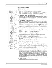
... to the group outputs and the ST output. NAL indicator will light. This indicator indicates that a signal is a 2-band equalizer with center frequencies, range, and type as shown below adjusts the stereo posi- MX400 User's Guide This switch is set to the center position, the same amount of the PEAK indicator. 6 4 EQ controls (HIGH, LOW) This is being input. 5 When the post EQ signal level reaches 3dB...
... to the group outputs and the ST output. NAL indicator will light. This indicator indicates that a signal is a 2-band equalizer with center frequencies, range, and type as shown below adjusts the stereo posi- MX400 User's Guide This switch is set to the center position, the same amount of the PEAK indicator. 6 4 EQ controls (HIGH, LOW) This is being input. 5 When the post EQ signal level reaches 3dB...

Owner's Manual
Page 10
... also use . You may listen to an individual module, or to monitor the signal of the stereo module regardless of the fader position, the settings of the ON switch, the group assign switches, or the AUX settings. As the name suggests, the signal is an acronym for Pre-Fader Listen. MX400 User's Guide This switch allows you to two or more modules simultaneously. 6 Front and rear panels 9 ON switch This switch turns the stereo module...
... also use . You may listen to an individual module, or to monitor the signal of the stereo module regardless of the fader position, the settings of the ON switch, the group assign switches, or the AUX settings. As the name suggests, the signal is an acronym for Pre-Fader Listen. MX400 User's Guide This switch allows you to two or more modules simultaneously. 6 Front and rear panels 9 ON switch This switch turns the stereo module...

Owner's Manual
Page 11
... AUX SEND signal. A position at the zero (0) marking is on . The group is the nominal level. MX400 User's Guide When off , no signal will be output from the corresponding GROUP OUT jack. 4 AFL (After Fader Listen) switch This monitors the GROUP signal. GROUP module 1 TO ST switch This sends the GROUP signal to the stereo bus. 2 PAN control This adjusts the panning of the signal sent to 10dB of gain. 2 PEAK indicator This indicator lights when the level of the AUX SEND output...
... AUX SEND signal. A position at the zero (0) marking is on . The group is the nominal level. MX400 User's Guide When off , no signal will be output from the corresponding GROUP OUT jack. 4 AFL (After Fader Listen) switch This monitors the GROUP signal. GROUP module 1 TO ST switch This sends the GROUP signal to the stereo bus. 2 PAN control This adjusts the panning of the signal sent to 10dB of gain. 2 PEAK indicator This indicator lights when the level of the AUX SEND output...

Owner's Manual
Page 12
... is turned on . This signal will light when the PFL switch of the ST2/MONITOR output. MX400 User's Guide When the switch is pressed in the "MONI" position, the signal will be taken from the PFL bus, AFL bus, or the 2TR IN jack. 4 ON switch This switch turns the ST2/MONITOR module on , the 2TR IN input signal will be output from the ST2/MONI OUT jack. 6 ST2/MONITOR fader This fader controls the signal level of...
... is turned on . This signal will light when the PFL switch of the ST2/MONITOR output. MX400 User's Guide When the switch is pressed in the "MONI" position, the signal will be taken from the PFL bus, AFL bus, or the 2TR IN jack. 4 ON switch This switch turns the ST2/MONITOR module on , the 2TR IN input signal will be output from the ST2/MONI OUT jack. 6 ST2/MONITOR fader This fader controls the signal level of...

Owner's Manual
Page 13
... supplied. The TAPE IN control adjusts the input signal level of the REC OUT jack. R MX400 User's Guide The nominal input level is the nominal output level. 5 5 0 0 0 5 5 10 10 15 15 20 20 25 25 30 30 40 40 ∞ ∞ L - Master module (L-ST1-R) 9 Master module (L-ST1-R) POWER PHANTOM 1 POWER indicator 1 2 This indicator lights when the power switch is turned on. 2 PHANTOM indicator This indicator lights when the PHANTOM switch is turned on /off. Headphones connected here can be output. 0 L-ST1-R faders...
... supplied. The TAPE IN control adjusts the input signal level of the REC OUT jack. R MX400 User's Guide The nominal input level is the nominal output level. 5 5 0 0 0 5 5 10 10 15 15 20 20 25 25 30 30 40 40 ∞ ∞ L - Master module (L-ST1-R) 9 Master module (L-ST1-R) POWER PHANTOM 1 POWER indicator 1 2 This indicator lights when the power switch is turned on. 2 PHANTOM indicator This indicator lights when the PHANTOM switch is turned on /off. Headphones connected here can be output. 0 L-ST1-R faders...

Owner's Manual
Page 14
... 3/4 or ST2/MONITOR L/R, 3) STEREO L/R. The "PEAK" position indicates that the output level is not pressed in ( ), the central meter group will indicate the GROUP 3/4 signal level. 10 Front and rear panels Meters PEAK +6 +4 +2 0 -2 -4 -7 -10 -15 -20 GROUP 1 GROUP 2 1 PEAK +6 +4 +2 0 -2 -4 -7 -10 -15 -20 GROUP 3 GROUP 4 L ST2/MONITOR R METER SELECT PEAK +6 +4 +2 0 -2 -4 -7 -10 -15 -20 L STEREO 1 R The MX400 provides six LED meters, and three types of output level can be monitored. The "0" position indicates the nominal output level. MX400 User's Guide
... 3/4 or ST2/MONITOR L/R, 3) STEREO L/R. The "PEAK" position indicates that the output level is not pressed in ( ), the central meter group will indicate the GROUP 3/4 signal level. 10 Front and rear panels Meters PEAK +6 +4 +2 0 -2 -4 -7 -10 -15 -20 GROUP 1 GROUP 2 1 PEAK +6 +4 +2 0 -2 -4 -7 -10 -15 -20 GROUP 3 GROUP 4 L ST2/MONITOR R METER SELECT PEAK +6 +4 +2 0 -2 -4 -7 -10 -15 -20 L STEREO 1 R The MX400 provides six LED meters, and three types of output level can be monitored. The "0" position indicates the nominal output level. MX400 User's Guide

Owner's Manual
Page 15
... output level: 0dB MX400 User's Guide Rear panel 11 Rear panel INPUT A 8 7 6 5 4 3 2 1 1 INPUT B 8 7 6 5 4 3 2 1 2 INPUT INSERT I /O jacks (0dB) These are 1/4" phone jacks patched in , and sleeve=ground. • Nominal input level: 0dB • Nominal output level: 0dB 4 DIRECT OUT jacks (0dB) These are unbalanced 1/4" phone jacks which input the signal for each input module. When the PHANTOM switch is turned on , make sure that those devices which do not require phantom power are connected to these jacks. Phantom power is on /off using the PHANTOM switch...
... output level: 0dB MX400 User's Guide Rear panel 11 Rear panel INPUT A 8 7 6 5 4 3 2 1 1 INPUT B 8 7 6 5 4 3 2 1 2 INPUT INSERT I /O jacks (0dB) These are 1/4" phone jacks patched in , and sleeve=ground. • Nominal input level: 0dB • Nominal output level: 0dB 4 DIRECT OUT jacks (0dB) These are unbalanced 1/4" phone jacks which input the signal for each input module. When the PHANTOM switch is turned on , make sure that those devices which do not require phantom power are connected to these jacks. Phantom power is on /off using the PHANTOM switch...

Owner's Manual
Page 16
... L -10dBV R L B R ST INPUT 4 L/ MONO R ST INPUT 1 L/ MONO A R L B R ST INPUT 3 L/ MONO R J 68 97 0 A B Phantom Power Warning 5 GROUP SUB IN jacks (+4dB) To prevent hazard or damage, connect only microphones and cables that conform to a DAT or cassette recorder. These jacks are selected by the A/B switch. • Nominal input level: +4dB or -10dB A ST INPUT 1/2 B jacks These are selected by the A/B switch. • Nominal input level: +4dB or -10dB MX400 User's Guide These jacks are RCA pin jacks which input a stereo source. These...
... L -10dBV R L B R ST INPUT 4 L/ MONO R ST INPUT 1 L/ MONO A R L B R ST INPUT 3 L/ MONO R J 68 97 0 A B Phantom Power Warning 5 GROUP SUB IN jacks (+4dB) To prevent hazard or damage, connect only microphones and cables that conform to a DAT or cassette recorder. These jacks are selected by the A/B switch. • Nominal input level: +4dB or -10dB A ST INPUT 1/2 B jacks These are selected by the A/B switch. • Nominal input level: +4dB or -10dB MX400 User's Guide These jacks are RCA pin jacks which input a stereo source. These...

Owner's Manual
Page 17
...=ground E ST INSERT I/O jacks (0dB) These are 1/4" phone jacks patched in front of the L-ST1-R fader of the master module. J PHANTOM power switch This switch turns the internal phantom power supply on /off . Rear panel 13 0VU *O (SPVOE B ST INPUT 3/4 jacks These are unbalanced 1/4" phone jacks which input a stereo source. • Nominal input level: +4dB or -10dB C AUX SEND jacks (+4dB) These are unbalanced 1/4" phone jacks which output the signal of the stereo L,R bus. • Nominal output level: +4dB I POWER switch This switch turns the power on /off...
...=ground E ST INSERT I/O jacks (0dB) These are 1/4" phone jacks patched in front of the L-ST1-R fader of the master module. J PHANTOM power switch This switch turns the internal phantom power supply on /off . Rear panel 13 0VU *O (SPVOE B ST INPUT 3/4 jacks These are unbalanced 1/4" phone jacks which input a stereo source. • Nominal input level: +4dB or -10dB C AUX SEND jacks (+4dB) These are unbalanced 1/4" phone jacks which output the signal of the stereo L,R bus. • Nominal output level: +4dB I POWER switch This switch turns the power on /off...

Owner's Manual
Page 18
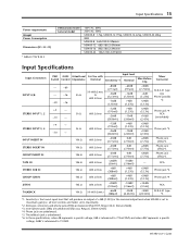
... EQ Input module HPF Input module GAIN control Meters (0 LED = +4dB* output level) Input module, stereo input module indicators AUX SEND indicators 20 Hz~20 kHz +1, -2dB (ST L/R, GROUP @ 600 Ω AUX SEND @ 600 Ω) Less than 0.1% (20 Hz~20 kHz @ 14dB*) (ST L/R, GROUP @ 600 Ω AUX SEND @ 600 Ω) -70dB (between adjacent channels) -70dB (between outputs) -128dB* equivalent input noise (CH 1~24) -96dB* residual noise (STEREO 1,2, GROUP 1~4, AUX SEND 1~5) -87dB* (STEREO 1,2, GROUP 1~4) Measured with master faders at nominal level and all assign switches...
... EQ Input module HPF Input module GAIN control Meters (0 LED = +4dB* output level) Input module, stereo input module indicators AUX SEND indicators 20 Hz~20 kHz +1, -2dB (ST L/R, GROUP @ 600 Ω AUX SEND @ 600 Ω) Less than 0.1% (20 Hz~20 kHz @ 14dB*) (ST L/R, GROUP @ 600 Ω AUX SEND @ 600 Ω) -70dB (between adjacent channels) -70dB (between outputs) -128dB* equivalent input noise (CH 1~24) -96dB* residual noise (STEREO 1,2, GROUP 1~4, AUX SEND 1~5) -87dB* (STEREO 1,2, GROUP 1~4) Measured with master faders at nominal level and all assign switches...
Owner's Manual
Page 19
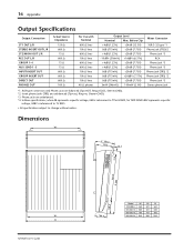
... MX400-8 17kg, MX400-12 19kg, MX400-16 22kg, MX400-24 28kg 80W MX400-8 562×180.2×596mm MX400-12 682×180.2×596mm MX400-16 802×180.2×596mm MX400-24 1042×180.2×596mm Input Specifications Input Connection INPUT A/B STEREO INPUT 1, 2 STEREO INPUT 3, 4 INPUT INSERT IN STEREO INSERT IN GROUP INSERT IN TAPE IN STEREO SUB IN GROUP SUB IN 2TR IN TALKBACK PAD GAIN Actual Load For Use with Input level Switch Control Impedance...
... MX400-8 17kg, MX400-12 19kg, MX400-16 22kg, MX400-24 28kg 80W MX400-8 562×180.2×596mm MX400-12 682×180.2×596mm MX400-16 802×180.2×596mm MX400-24 1042×180.2×596mm Input Specifications Input Connection INPUT A/B STEREO INPUT 1, 2 STEREO INPUT 3, 4 INPUT INSERT IN STEREO INSERT IN GROUP INSERT IN TAPE IN STEREO SUB IN GROUP SUB IN 2TR IN TALKBACK PAD GAIN Actual Load For Use with Input level Switch Control Impedance...
Owner's Manual
Page 20
... Output Specifications Output Connection ST1 OUT L/R STEREO INSERT OUT L/R ST2/MONI OUT L/R REC OUT L/R GROUP 1~4 AUX SEND 1~5 INPUT INSERT OUT GROUP INSERT OUT DIRECT OUT PHONES OUT Actual Source Impedance 150 Ω 600 Ω 75 Ω 600 Ω 75 Ω 75 Ω 600 Ω 600 Ω 600 Ω 100 Ω For Use with Nominal 600 Ω lines 10k Ω lines 600 Ω lines 10k Ω lines...
... Output Specifications Output Connection ST1 OUT L/R STEREO INSERT OUT L/R ST2/MONI OUT L/R REC OUT L/R GROUP 1~4 AUX SEND 1~5 INPUT INSERT OUT GROUP INSERT OUT DIRECT OUT PHONES OUT Actual Source Impedance 150 Ω 600 Ω 75 Ω 600 Ω 75 Ω 75 Ω 600 Ω 600 Ω 600 Ω 100 Ω For Use with Nominal 600 Ω lines 10k Ω lines 600 Ω lines 10k Ω lines...
Owner's Manual
Page 75
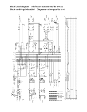
... CH IN [-16] -60 GROUP SUB IN ST SUB IN [+4] TAPE IN [-10dBV] [-3] AUX [-6] 1 2 3 GROUP 4 L R STEREO 1 2 3 AUX 4 5 L R PFL PFL CTRL AFL AFL CTRL GROUP INSERT I/O 0dB 1-4 SUM INV TO ST PAN (+V) AFL ST INSERT I/O L 0dB SUM INV SUM INV ST INSERT I /O * 0dB 1- PAD HA A B 20dB GAIN HPF 80 EQ EQ LOW MID MID FREQ HIGH PEAK SIGNAL BA L/ MONO A R ST INPUT 1-2 L B R L/ MONO ST INPUT 3-4 R PAD HA +4 -10 PAD...
... CH IN [-16] -60 GROUP SUB IN ST SUB IN [+4] TAPE IN [-10dBV] [-3] AUX [-6] 1 2 3 GROUP 4 L R STEREO 1 2 3 AUX 4 5 L R PFL PFL CTRL AFL AFL CTRL GROUP INSERT I/O 0dB 1-4 SUM INV TO ST PAN (+V) AFL ST INSERT I/O L 0dB SUM INV SUM INV ST INSERT I /O * 0dB 1- PAD HA A B 20dB GAIN HPF 80 EQ EQ LOW MID MID FREQ HIGH PEAK SIGNAL BA L/ MONO A R ST INPUT 1-2 L B R L/ MONO ST INPUT 3-4 R PAD HA +4 -10 PAD...


