
Owner's Manual
Page 3
... master section 21 Rear input/output block 22 Channel I/O connectors section 22 Master I/O connectors section 22 Power section 23 Basic Operations and Display 24 Viewing the display 24 Operations of the screen 25 Using Effects (FX 26 Applying effects 26 Detailed effect settings 26 Applying two effects simultaneously 27 Displaying FX1 and... List 42 Effect Program List 43 Parameter List 44 Jack List 46 Dimensions 47 Specifications 48 Index 51 Block Diagram and Level Diagram 52 MGP32X/MGP24X Owner's Manual 3
... master section 21 Rear input/output block 22 Channel I/O connectors section 22 Master I/O connectors section 22 Power section 23 Basic Operations and Display 24 Viewing the display 24 Operations of the screen 25 Using Effects (FX 26 Applying effects 26 Detailed effect settings 26 Applying two effects simultaneously 27 Displaying FX1 and... List 42 Effect Program List 43 Parameter List 44 Jack List 46 Dimensions 47 Specifications 48 Index 51 Block Diagram and Level Diagram 52 MGP32X/MGP24X Owner's Manual 3
Owner's Manual
Page 6
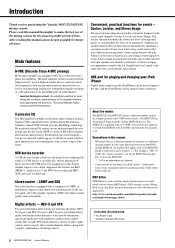
...features an inverted Darlington circuit* used in on the mono input channels features Xpressive EQ, which effectively models analog EQ utilizing Yamaha's famed VCM (Virtual Circuitry Modeling) technology. Ducker, Leveler, and Stereo Image The mixer features three exceptionally convenient features for ... and iPad. After reading this manual • Whenever there is equipped with 16 COMP control knobs for channels 9-24 and the MGP24X with Class-A discrete microphone preamplifiers. We analyzed vintage EQ analog circuits and redesigned the technology specifically for the longest ...
...features an inverted Darlington circuit* used in on the mono input channels features Xpressive EQ, which effectively models analog EQ utilizing Yamaha's famed VCM (Virtual Circuitry Modeling) technology. Ducker, Leveler, and Stereo Image The mixer features three exceptionally convenient features for ... and iPad. After reading this manual • Whenever there is equipped with 16 COMP control knobs for channels 9-24 and the MGP24X with Class-A discrete microphone preamplifiers. We analyzed vintage EQ analog circuits and redesigned the technology specifically for the longest ...
Owner's Manual
Page 11
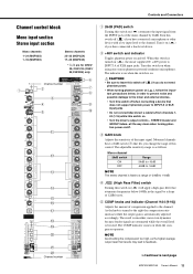
...'s Manual 11 Controls and Connectors Channel control block Mono input section Stereo input section Mono channels 1-24 (MGP32X) 1-16 (MGP24X) Stereo channels 25-32 (MGP32X) 17-24 (MGP24X) * y-!0 are attenuated while the overall level is boosted. Channel number q 26dB (PAD) switch Turning this switch off ( )...not need • When turning phantom power on ( ) if you have connected a line-level device. t COMP knobs and indicator (Channel 9-24 {9-16}) Adjusts the amount of compression applied to INPUT A of XLR input jacks • Do not connect/disconnect a cable to +10dB. The...
...'s Manual 11 Controls and Connectors Channel control block Mono input section Stereo input section Mono channels 1-24 (MGP32X) 1-16 (MGP24X) Stereo channels 25-32 (MGP32X) 17-24 (MGP24X) * y-!0 are attenuated while the overall level is boosted. Channel number q 26dB (PAD) switch Turning this switch off ( )...not need • When turning phantom power on ( ) if you have connected a line-level device. t COMP knobs and indicator (Channel 9-24 {9-16}) Adjusts the amount of compression applied to INPUT A of XLR input jacks • Do not connect/disconnect a cable to +10dB. The...

Owner's Manual
Page 12
...sound output level differs for each of the selected input source (CH24 {CH16} or GROUP1) comes on . Channel number Channel number 12 MGP32X/MGP24X Owner's Manual y DUCKER SOURCE indicator The indicator of the three bands. When the switch is set at a fixed 2.5kHz center frequency. ... can be input to be selected on ( ) lowers the volume of your iPod/iPhone. Controls and Connectors Mono channels 1-24 (MGP32X) 1-16 (MGP24X) Stereo channels 25-32 (MGP32X) 17-24 (MGP24X) * y-!0 are mixed at a certain percentage for a more natural stereo image, and in which left attenuates the band....
...sound output level differs for each of the selected input source (CH24 {CH16} or GROUP1) comes on . Channel number Channel number 12 MGP32X/MGP24X Owner's Manual y DUCKER SOURCE indicator The indicator of the three bands. When the switch is set at a fixed 2.5kHz center frequency. ... can be input to be selected on ( ) lowers the volume of your iPod/iPhone. Controls and Connectors Mono channels 1-24 (MGP32X) 1-16 (MGP24X) Stereo channels 25-32 (MGP32X) 17-24 (MGP24X) * y-!0 are mixed at a certain percentage for a more natural stereo image, and in which left attenuates the band....
Owner's Manual
Page 16
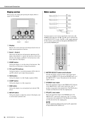
... or function. Use these meters can be monitored through the MONITOR OUT jacks and the PHONES jack. y COMP button Calls up the display to pages 24-25 for the selected signals come on the display. w STEREO level meter Shows the signal level output to the PHONES jack or the GROUP OUT... point. NOTE The PFL signal has display priority over the AFL signal when an input channel's PFL switch is for the functions on . 16 MGP32X/MGP24X Owner's Manual Rotate Knob 1 to operate the functions on the lower left side of FX1 (effect1) and FX2 (effect2) and to set the Graphic equalizer...
... or function. Use these meters can be monitored through the MONITOR OUT jacks and the PHONES jack. y COMP button Calls up the display to pages 24-25 for the selected signals come on the display. w STEREO level meter Shows the signal level output to the PHONES jack or the GROUP OUT... point. NOTE The PFL signal has display priority over the AFL signal when an input channel's PFL switch is for the functions on . 16 MGP32X/MGP24X Owner's Manual Rotate Knob 1 to operate the functions on the lower left side of FX1 (effect1) and FX2 (effect2) and to set the Graphic equalizer...

Owner's Manual
Page 19
...connected USB device. • TO STEREO ( ): Sends to the STEREO L/R bus. • TO MONITOR ( ): Sends to the MONITOR OUT jacks and PHONES jack. MGP32X/MGP24X Owner's Manual 19 w TO STEREO/TO MONITOR switch Determines the destination of the signal output from the connected iPod/iPhone. • TO STEREO ( ): Sends to... signal output from the connected iPod/iPhone. NOTE If you want to this TRS phone jack. NOTE CH29/30, 31/32 {CH21/22,23/24} can be selected as the MONITOR OUT jacks. The PHONES jack outputs the same signal as the destinations of each respective bus. e MONITOR knob...
...connected USB device. • TO STEREO ( ): Sends to the STEREO L/R bus. • TO MONITOR ( ): Sends to the MONITOR OUT jacks and PHONES jack. MGP32X/MGP24X Owner's Manual 19 w TO STEREO/TO MONITOR switch Determines the destination of the signal output from the connected iPod/iPhone. • TO STEREO ( ): Sends to... signal output from the connected iPod/iPhone. NOTE If you want to this TRS phone jack. NOTE CH29/30, 31/32 {CH21/22,23/24} can be selected as the MONITOR OUT jacks. The PHONES jack outputs the same signal as the destinations of each respective bus. e MONITOR knob...
Owner's Manual
Page 22
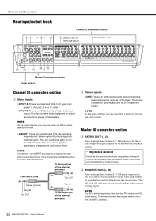
...phone plugs to these jacks to connect channels to your monitor system. Use a separately-sold Yamaha insertion cable (YIC025/050/070). These jacks output the signal adjusted by induced noise. ... for the various buses. NOTE Connection to turn off all PFL switches. 22 MGP32X/MGP24X Owner's Manual NOTE On any given channel, you may use either a phone or...Controls and Connectors Rear input/output block Channel I/O connectors section CH25/26-31/32 {CH17/18-23/24} CH1-24 {CH1-16} Master I/O connectors section Power section Channel I /O connectors section e MATRIX OUT (1, ...
...phone plugs to these jacks to connect channels to your monitor system. Use a separately-sold Yamaha insertion cable (YIC025/050/070). These jacks output the signal adjusted by induced noise. ... for the various buses. NOTE Connection to turn off all PFL switches. 22 MGP32X/MGP24X Owner's Manual NOTE On any given channel, you may use either a phone or...Controls and Connectors Rear input/output block Channel I/O connectors section CH25/26-31/32 {CH17/18-23/24} CH1-24 {CH1-16} Master I/O connectors section Power section Channel I /O connectors section e MATRIX OUT (1, ...
Owner's Manual
Page 24
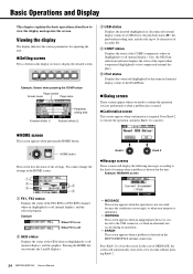
... to the USB connector, or when an abnormal exit occurs during an operation. • ERROR This screen appears when a problem is detected in the MGP32X/MGP24X internal connection. Press Knob 2 to execute the operation, and press Knob 1 to 16 characters) of an audio file. q w r e t q FX1,... status of the iPod/iPhone. Dialog screen These screens appear when you need to close after a few seconds without pressing Knob 2. 24 MGP32X/MGP24X Owner's Manual r COMP status Displays the status of the COMP (compressor) when on When FX1 is required. Press Knob 2 to confirm the...
... to the USB connector, or when an abnormal exit occurs during an operation. • ERROR This screen appears when a problem is detected in the MGP32X/MGP24X internal connection. Press Knob 2 to execute the operation, and press Knob 1 to 16 characters) of an audio file. q w r e t q FX1,... status of the iPod/iPhone. Dialog screen These screens appear when you need to close after a few seconds without pressing Knob 2. 24 MGP32X/MGP24X Owner's Manual r COMP status Displays the status of the COMP (compressor) when on When FX1 is required. Press Knob 2 to confirm the...
Owner's Manual
Page 36
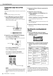
...make the following settings. NOTE Avoid adjusting both the STEREO/MONITOR level control (USB IN knob) and the level control for channels 31/32 {23/24} to set the parameter value. STEREO, ing signal source MATRIX1/2 Adjustment of the recording level -48dB to +24dB Selection of the record- Operate .../24} at the same time because of the delay of the signal path. 5. Rotate Knob 1 to select the desired parameter, and then rotate Knob 2 to "iPod IN" ( ). Set to TO STEREO () To output to MONITOR OUT Set the TO STEREO/TO MONITOR switch in the sound. 36 MGP32X/MGP24X ...
...make the following settings. NOTE Avoid adjusting both the STEREO/MONITOR level control (USB IN knob) and the level control for channels 31/32 {23/24} to set the parameter value. STEREO, ing signal source MATRIX1/2 Adjustment of the recording level -48dB to +24dB Selection of the record- Operate .../24} at the same time because of the delay of the signal path. 5. Rotate Knob 1 to select the desired parameter, and then rotate Knob 2 to "iPod IN" ( ). Set to TO STEREO () To output to MONITOR OUT Set the TO STEREO/TO MONITOR switch in the sound. 36 MGP32X/MGP24X ...
Owner's Manual
Page 37
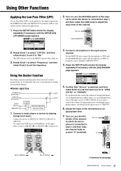
...on ( ) the ON switch of an announcer coming in on another channel. Ducker signal flow CH29/30 (CH21/22) CH31/32 (CH23/24) CH24 (CH16) GROUP1 DUCKER SOURCE Volume detection Volume control 1. Press the SETUP button below the display repeatedly if necessary until the SETUP (2/4) LPF (MONO...of background music to "CH24 {CH16}" or "GROUP1." Turn on ( ) the DUCKER switch of the channel. Connect a music player or device for the MGP24X unit connect the microphone to CH16, or assign the source channel to USB IN ( ) or iPod IN ( ) respectively. 3. Press the SETUP button below...
...on ( ) the ON switch of an announcer coming in on another channel. Ducker signal flow CH29/30 (CH21/22) CH31/32 (CH23/24) CH24 (CH16) GROUP1 DUCKER SOURCE Volume detection Volume control 1. Press the SETUP button below the display repeatedly if necessary until the SETUP (2/4) LPF (MONO...of background music to "CH24 {CH16}" or "GROUP1." Turn on ( ) the DUCKER switch of the channel. Connect a music player or device for the MGP24X unit connect the microphone to CH16, or assign the source channel to USB IN ( ) or iPod IN ( ) respectively. 3. Press the SETUP button below...

Owner's Manual
Page 38
... Time When the volume of CH29/30 {CH21/22}. NOTE For details about the parameters, refer to the Appendix (page 45). 38 MGP32X/MGP24X Owner's Manual Each parameter lets you make the following settings. • Thresh (Threshold): Threshold level at which the Leveler is connected, turn ...DUCKER SOURCE drops below the threshold level "#1" in the parameter name indicates CH29/30 {CH21/22}, and "#2" indicates CH31/32 {CH23/24}. Release Using the Leveler function The Leveler function automatically maintains a consistent sound volume, even when using sound sources that the PFL/AFL ...
... Time When the volume of CH29/30 {CH21/22}. NOTE For details about the parameters, refer to the Appendix (page 45). 38 MGP32X/MGP24X Owner's Manual Each parameter lets you make the following settings. • Thresh (Threshold): Threshold level at which the Leveler is connected, turn ...DUCKER SOURCE drops below the threshold level "#1" in the parameter name indicates CH29/30 {CH21/22}, and "#2" indicates CH31/32 {CH23/24}. Release Using the Leveler function The Leveler function automatically maintains a consistent sound volume, even when using sound sources that the PFL/AFL ...
Owner's Manual
Page 40
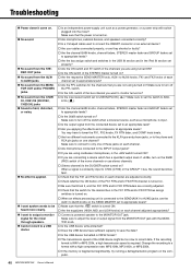
... switch of the bus channel you want to output a monitor signal for the channels that the FX1 and FX2 knobs on the computer. 40 MGP32X/MGP24X Owner's Manual Make sure to adjust the level of output signal from the MONITOR OUT jack with the MONITOR knob. Is the USB device... AUX6 jacks No sound from the MONITOR OUT and/or PHONES jacks No sound from the CH29/ 30, CH31/32 {CH21/22, CH23/24} jacks Sound is faint, distorted, or noisy. No effect is applied. I want spoken words to be too slow to record data. Make...
... switch of the bus channel you want to output a monitor signal for the channels that the FX1 and FX2 knobs on the computer. 40 MGP32X/MGP24X Owner's Manual Make sure to adjust the level of output signal from the MONITOR OUT jack with the MONITOR knob. Is the USB device... AUX6 jacks No sound from the MONITOR OUT and/or PHONES jacks No sound from the CH29/ 30, CH31/32 {CH21/22, CH23/24} jacks Sound is faint, distorted, or noisy. No effect is applied. I want spoken words to be too slow to record data. Make...

Owner's Manual
Page 45
... its normal gain once the trigger signal level drops below the threshold. This determines the amount of attenuation when the ducker is channel 24 {16} or GROUP1. MGP32X/MGP24X Owner's Manual 45 A larger value results in a stronger compression effect. This determines the level of input signal required to active the ducker. This...
... its normal gain once the trigger signal level drops below the threshold. This determines the amount of attenuation when the ducker is channel 24 {16} or GROUP1. MGP32X/MGP24X Owner's Manual 45 A larger value results in a stronger compression effect. This determines the level of input signal required to active the ducker. This...

Owner's Manual
Page 49
...Level Nominal Max. before clip STEREO OUT L, R 75 Ω 600 Ω Lines +4 dBu (1.23 V) +24 dBu (12.3 V) MONO OUT GROUP OUT 1-4 AUX SEND 1-6 MATRIX OUT 1-2 MONO CH INSERT OUT MGP32X: 1-24 MGP24X: 1-16 ST CH INSERT OUT L, R MONITOR OUT L, R PHONES OUT 75 Ω 150 Ω 75...*3 Phone Jack*3 Phone Jack*2 Stereo Phone Jack MGP32X/MGP24X Owner's Manual 49 Appendix Analog Input Characteristics Input Terminals MONO CH Input MGP32X: 1-24 MGP24X: 1-16 ST CH Input MGP32X: 25-32 MGP24X: 17-24 MONO CH INSERT Input MGP32X: 1-24 MGP24X: 1-16 ST CH INSERT Input L, R TALKBACK Input...
...Level Nominal Max. before clip STEREO OUT L, R 75 Ω 600 Ω Lines +4 dBu (1.23 V) +24 dBu (12.3 V) MONO OUT GROUP OUT 1-4 AUX SEND 1-6 MATRIX OUT 1-2 MONO CH INSERT OUT MGP32X: 1-24 MGP24X: 1-16 ST CH INSERT OUT L, R MONITOR OUT L, R PHONES OUT 75 Ω 150 Ω 75...*3 Phone Jack*3 Phone Jack*2 Stereo Phone Jack MGP32X/MGP24X Owner's Manual 49 Appendix Analog Input Characteristics Input Terminals MONO CH Input MGP32X: 1-24 MGP24X: 1-16 ST CH Input MGP32X: 25-32 MGP24X: 17-24 MONO CH INSERT Input MGP32X: 1-24 MGP24X: 1-16 ST CH INSERT Input L, R TALKBACK Input...

Owner's Manual
Page 50
...Voltage +48V Lamp XLR-4-31 type,The Lamp voltage is 12V DC between 3 and 4 pins of the clipping level. For updated information, check the Yamaha Pro Audio web site (http://www.yamahaproaudio.com/). * Specifications and descriptions in every locale, please check with your iPod/iOS software version. Lamp can ... Input Channel HPF 100 Hz, 12 dB/oct Input Channel EQ HIGH 8 kHz, shelving MID MGP32X: CHs 1-24, 29-32: 250 Hz to 5 kHz, peaking CHs 25-28: 2.5 kHz, peaking MGP24X: CHs 1-16, 21-24: 250 Hz to 5 kHz, peaking CHs 17-20: 2.5 kHz, peaking LOW 125 Hz, shelving Input Channel...
...Voltage +48V Lamp XLR-4-31 type,The Lamp voltage is 12V DC between 3 and 4 pins of the clipping level. For updated information, check the Yamaha Pro Audio web site (http://www.yamahaproaudio.com/). * Specifications and descriptions in every locale, please check with your iPod/iOS software version. Lamp can ... Input Channel HPF 100 Hz, 12 dB/oct Input Channel EQ HIGH 8 kHz, shelving MID MGP32X: CHs 1-24, 29-32: 250 Hz to 5 kHz, peaking CHs 25-28: 2.5 kHz, peaking MGP24X: CHs 1-16, 21-24: 250 Hz to 5 kHz, peaking CHs 17-20: 2.5 kHz, peaking LOW 125 Hz, shelving Input Channel...

Owner's Manual
Page 51
... Bus 13 C Compressor 11, 31 Compressor program 32 Condenser microphone 9, 11 Contrast 25 D Delay 26 Delay time 17 DI box (direct box 9 Dialog screen 24 Display 16, 24 Ducker 6, 12, 37, 38 E Echo 26 Effect 13, 26 Effect programs 26 Effect return 17 Equalizer 12 F Factory default settings 39 Fast forwarding 35... Available recording time 33 Capacity 33 File format 33 Format 33 Playing back 33 Recording 33 USB device recorder 15 V Volume balance 13 Appendix MGP32X/MGP24X Owner's Manual 51
... Bus 13 C Compressor 11, 31 Compressor program 32 Condenser microphone 9, 11 Contrast 25 D Delay 26 Delay time 17 DI box (direct box 9 Dialog screen 24 Display 16, 24 Ducker 6, 12, 37, 38 E Echo 26 Effect 13, 26 Effect programs 26 Effect return 17 Equalizer 12 F Factory default settings 39 Fast forwarding 35... Available recording time 33 Capacity 33 File format 33 Format 33 Playing back 33 Recording 33 USB device recorder 15 V Volume balance 13 Appendix MGP32X/MGP24X Owner's Manual 51

