
Owner's Manual
Page 6
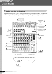
...Mixer Basics Quick Guide Mixer Basics Getting Sound to the input devices you are using. 2 Microphones, instruments 1, 4 GAIN controls 4 PEAK indicators Equalizer PAN 5 ON switches 4 PFL switches 5 ST switches ON ON ON ON ON ON ON ON ON 1, 7 Channel faders 1 GROUP 1-2 fader 2 Speakers Power Amp 2, 4 Monitor Speakers 2, 4 Headphones 3 PHANTOM switch 4, 7 Level meter 1, 6, 7 STEREO... OUT Master fader 1, 3 POWER switch 6 MG124CX/MG124C Owner's Manual Note that operations and procedures will vary somewhat according to...
...Mixer Basics Quick Guide Mixer Basics Getting Sound to the input devices you are using. 2 Microphones, instruments 1, 4 GAIN controls 4 PEAK indicators Equalizer PAN 5 ON switches 4 PFL switches 5 ST switches ON ON ON ON ON ON ON ON ON 1, 7 Channel faders 1 GROUP 1-2 fader 2 Speakers Power Amp 2, 4 Monitor Speakers 2, 4 Headphones 3 PHANTOM switch 4, 7 Level meter 1, 6, 7 STEREO... OUT Master fader 1, 3 POWER switch 6 MG124CX/MG124C Owner's Manual Note that operations and procedures will vary somewhat according to...
Owner's Manual
Page 7
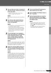
...guitars and basses through an intermediary device such as a direct box, preamp, or amp simulator. MG124CX/MG124C Owner's Manual 7 Note that the PHONES jack outputs the pre-fader signal from all the way down. * STEREO OUT Master Fader, Channel Fader, GROUP 1-2 Fader, Gain Control, etc. Reverse this order ... via the headphones. 5 Turn on which the PFL switch is turned off . NOTE Set the equalizer and the pan controls to avoid distortion. Mixer Basics Quick Guide 1 Be sure that your speakers, power up the devices in degraded sound and noise. 3 To avoid damage to the power...
...guitars and basses through an intermediary device such as a direct box, preamp, or amp simulator. MG124CX/MG124C Owner's Manual 7 Note that the PHONES jack outputs the pre-fader signal from all the way down. * STEREO OUT Master Fader, Channel Fader, GROUP 1-2 Fader, Gain Control, etc. Reverse this order ... via the headphones. 5 Turn on which the PFL switch is turned off . NOTE Set the equalizer and the pan controls to avoid distortion. Mixer Basics Quick Guide 1 Be sure that your speakers, power up the devices in degraded sound and noise. 3 To avoid damage to the power...
Owner's Manual
Page 13
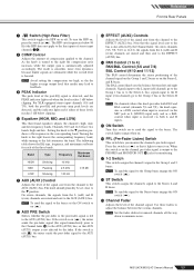
...if either of the channel signal on the Group 1 and 2 buses or on ( ), the mixer sends the pre-fader signal (the signal immediately prior to the Channel fader I) to the AUX ... switch in the corresponding band. G 1-2 Switch This switch assigns the channel's signal to the Stereo L bus; As the knob is turned to adjust the balance between left attenuates the band. ... Channel Fader Adjusts the level of the post-EQ signal is not affected by the Channel fader. MG124CX/MG124C Owner's Manual 13 Setting the knob to the t position produces a flat response in ...
...if either of the channel signal on the Group 1 and 2 buses or on ( ), the mixer sends the pre-fader signal (the signal immediately prior to the Channel fader I) to the AUX ... switch in the corresponding band. G 1-2 Switch This switch assigns the channel's signal to the Stereo L bus; As the knob is turned to adjust the balance between left attenuates the band. ... Channel Fader Adjusts the level of the post-EQ signal is not affected by the Channel fader. MG124CX/MG124C Owner's Manual 13 Setting the knob to the t position produces a flat response in ...
Owner's Manual
Page 14
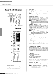
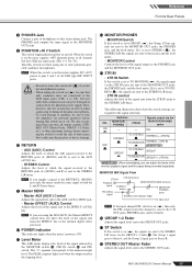
...switch, and the PFL switches on the signal output via the STEREO OUT jacks. Reference Front & Rear Panels Master Control Section 2 1 5 3 7 4 6 8 B 9 0 C A D E G F H MG124CX * impedance balanced Since the hot and cold terminals of a multi-track recorder, external mixer, or other monitoring system. • EFFECT (AUX2) This...such as monaural and will send the identical signal to your main speakers. NOTE The mixer's STEREO OUT Master Fader has no affect on the input channels. 14 MG124CX/MG124C Owner's Manual The signal received by these jacks when you want to connect a...
...switch, and the PFL switches on the signal output via the STEREO OUT jacks. Reference Front & Rear Panels Master Control Section 2 1 5 3 7 4 6 8 B 9 0 C A D E G F H MG124CX * impedance balanced Since the hot and cold terminals of a multi-track recorder, external mixer, or other monitoring system. • EFFECT (AUX2) This...such as monaural and will send the identical signal to your main speakers. NOTE The mixer's STEREO OUT Master Fader has no affect on the input channels. 14 MG124CX/MG124C Owner's Manual The signal received by these jacks when you want to connect a...
Owner's Manual
Page 15
... switch is sent to the C-R OUT jacks, PHONES jacks, and level meter. MG124CX/MG124C Owner's Manual 15 We also recommend that channel is on the mixer supplies +48V phantom power to all output controls (STEREO OUT Master Fader, GROUP 1-2 Fader, etc.) to their minimum settings before turning ... via the MONITOR/PHONES jacks PFL OFF STEREO GROUP TO STEREO STEREO (+ 2TR IN) TO MONITOR STEREO + 2TR IN * TO STEREO GROUP TO MONITOR GROUP (+ 2TR IN) * : When overdubbing, you supply a signal to the RETURN L (MONO) jack only, the mixer sends the same signal to the phantom power supply. D ...
... switch is sent to the C-R OUT jacks, PHONES jacks, and level meter. MG124CX/MG124C Owner's Manual 15 We also recommend that channel is on the mixer supplies +48V phantom power to all output controls (STEREO OUT Master Fader, GROUP 1-2 Fader, etc.) to their minimum settings before turning ... via the MONITOR/PHONES jacks PFL OFF STEREO GROUP TO STEREO STEREO (+ 2TR IN) TO MONITOR STEREO + 2TR IN * TO STEREO GROUP TO MONITOR GROUP (+ 2TR IN) * : When overdubbing, you supply a signal to the RETURN L (MONO) jack only, the mixer sends the same signal to the phantom power supply. D ...
Owner's Manual
Page 16
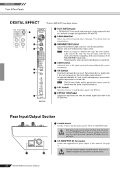
Reference Front & Rear Panels DIGITAL EFFECT *Only the MG124CX has digital effects. 1 2 3 4 5 ON 6 7 MG124CX 1 FOOT SWITCH Jack A YAMAHA FC5 foot switch (sold separately) can be connected to this jack and used to toggle the digital effects ON and OFF. 2 PROGRAM ...effect (regardless of the current position of the signal sent from the internal digital effect unit to use the mixer for the selected effect. NOTE When you do not plan to the STEREO bus. CAUTION 16 MG124CX/MG124C Owner's Manual Rear Input/Output Section 1 POWER Switch Use this connector (see page 5).
Reference Front & Rear Panels DIGITAL EFFECT *Only the MG124CX has digital effects. 1 2 3 4 5 ON 6 7 MG124CX 1 FOOT SWITCH Jack A YAMAHA FC5 foot switch (sold separately) can be connected to this jack and used to toggle the digital effects ON and OFF. 2 PROGRAM ...effect (regardless of the current position of the signal sent from the internal digital effect unit to use the mixer for the selected effect. NOTE When you do not plan to the STEREO bus. CAUTION 16 MG124CX/MG124C Owner's Manual Rear Input/Output Section 1 POWER Switch Use this connector (see page 5).
Owner's Manual
Page 18
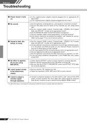
... switches are they shorted? ❑ If the above checks do not identify the problem, call Yamaha for service. (Refer to the page 71 for a list of the channels you are using MG124CX) ❑ Check that the EFFECT control on each channel is correctly adjusted. ❑ Be ...properly plugged into the mixer? ■ No sound. ❑ Are microphones, external devices, and speakers connected correctly? ❑ Are the ON switch and ST switch of service centers.) ■ Sound is faint, distorted, or noisy. ❑ Are the channel GAIN controls, Channel fader, STEREO OUT master fader and...
... switches are they shorted? ❑ If the above checks do not identify the problem, call Yamaha for service. (Refer to the page 71 for a list of the channels you are using MG124CX) ❑ Check that the EFFECT control on each channel is correctly adjusted. ❑ Be ...properly plugged into the mixer? ■ No sound. ❑ Are microphones, external devices, and speakers connected correctly? ❑ Are the ON switch and ST switch of service centers.) ■ Sound is faint, distorted, or noisy. ❑ Are the channel GAIN controls, Channel fader, STEREO OUT master fader and...


