Service Manual
Page 10
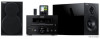
...etc. This unit supports DAB tuning. Section) (L/R drive, 1 kHz, 10 % THD, 6 ohms 20 W + 20 W Rated Output Voltage/Output Impedance SUBWOOFER 2.0 V/47 k-ohms Headphone Jack Rated Output/Output Impedance CD etc., 1 kHz, 150 mV 0.6 V/32 ohms Frequency Response 20 Hz to product improvements. and... other countries. CRX-330/NS-BP100 10 B British model "iPod" is a trademark of Apple Inc., registered in the U.S. CRX-330/NS-BP100 ■ SPECIFICATIONS CRX-330 ■ Audio Section Minimum RMS Output Power (Power Amp.
...etc. This unit supports DAB tuning. Section) (L/R drive, 1 kHz, 10 % THD, 6 ohms 20 W + 20 W Rated Output Voltage/Output Impedance SUBWOOFER 2.0 V/47 k-ohms Headphone Jack Rated Output/Output Impedance CD etc., 1 kHz, 150 mV 0.6 V/32 ohms Frequency Response 20 Hz to product improvements. and... other countries. CRX-330/NS-BP100 10 B British model "iPod" is a trademark of Apple Inc., registered in the U.S. CRX-330/NS-BP100 ■ SPECIFICATIONS CRX-330 ■ Audio Section Minimum RMS Output Power (Power Amp.
Service Manual
Page 44
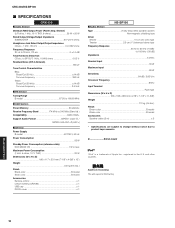
...D218 E5 D220 F3 D221 G4 3 D224 H4 D225 H3 81 54 D226 I3 D227 I4 D228 E3 4 1 D229 E3 D230 D3 IC209 85 28 1 SUBWOOFER OUT IC203 D231 D3 D240 D3 D241 D3 4 IC203 E4 IC205 H3 15 14 CB202 IC207 E3 IC208 D5 IC209 C3 IC210 D3 A 1 B 2 ... (16 pin) 2 IC211 (12 pin) 2 IC211 (12 pin) AC cable ON AC cable OFF AC cable ON LD_GND N.C. Location No replacement part available. A B C CRX-330/NS-BP100 1 ■ PRINTED CIRCUIT BOARDS D E POWER (1) (W2) POWER (1) (W4) AMPGND AMPGND +15V +15V MAIN (1) P.C.B. (Side A) • Semiconductor Location Ref No. PD DVD_VR...
...D218 E5 D220 F3 D221 G4 3 D224 H4 D225 H3 81 54 D226 I3 D227 I4 D228 E3 4 1 D229 E3 D230 D3 IC209 85 28 1 SUBWOOFER OUT IC203 D231 D3 D240 D3 D241 D3 4 IC203 E4 IC205 H3 15 14 CB202 IC207 E3 IC208 D5 IC209 C3 IC210 D3 A 1 B 2 ... (16 pin) 2 IC211 (12 pin) 2 IC211 (12 pin) AC cable ON AC cable OFF AC cable ON LD_GND N.C. Location No replacement part available. A B C CRX-330/NS-BP100 1 ■ PRINTED CIRCUIT BOARDS D E POWER (1) (W2) POWER (1) (W4) AMPGND AMPGND +15V +15V MAIN (1) P.C.B. (Side A) • Semiconductor Location Ref No. PD DVD_VR...

Service Manual
Page 51
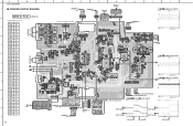
... VOLINL 12 /2dB stepVolume 0~87dB,-∞ IGOUTR 13 0~+20dB /2dB step Volume VOLINR 14 0~87dB,-∞ MCU I J K L M N CRX-330/NS-BP100 4.8 4.8 12.0 4.8 IC205 4.8 4.8 IC205 4.8 0 4.8 2.4 2.4 4.8 2.4 2.4 IC207 2.4 0 2.4 2.4 2.4 IC207 0 4.8 4.8 IC209 4.8 0 0.7 0 0 0.7 0 3.2 3.2 -27.4 0 0.7 0 0 0 0.7 12.0 4.8 4.8 4.8 IC209 0 3.2 0 3.2 SW OUT 0 -26.6 0 0 -27.0 0 SUBWOOFER OUT No replacement part available. OUTPUT1 1 8 2. -INPUT1 3. +INPUT1 2 7 4. OUTPUT2 4 5 8. 1 2 3 4 5 6 7 8 9 10 A B C D SCHEMATIC DIAGRAMS MAIN 1/3 W201 Page 53 M2...
... VOLINL 12 /2dB stepVolume 0~87dB,-∞ IGOUTR 13 0~+20dB /2dB step Volume VOLINR 14 0~87dB,-∞ MCU I J K L M N CRX-330/NS-BP100 4.8 4.8 12.0 4.8 IC205 4.8 4.8 IC205 4.8 0 4.8 2.4 2.4 4.8 2.4 2.4 IC207 2.4 0 2.4 2.4 2.4 IC207 0 4.8 4.8 IC209 4.8 0 0.7 0 0 0.7 0 3.2 3.2 -27.4 0 0.7 0 0 0 0.7 12.0 4.8 4.8 4.8 IC209 0 3.2 0 3.2 SW OUT 0 -26.6 0 0 -27.0 0 SUBWOOFER OUT No replacement part available. OUTPUT1 1 8 2. -INPUT1 3. +INPUT1 2 7 4. OUTPUT2 4 5 8. 1 2 3 4 5 6 7 8 9 10 A B C D SCHEMATIC DIAGRAMS MAIN 1/3 W201 Page 53 M2...
Owners Manual
Page 5
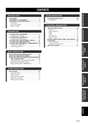
INTRODUCTION PREPARATION CONTENTS INTRODUCTION FEATURES 2 SUPPLIED ACCESSORIES 2 CONTROLS AND FUNCTIONS 3 Front panel 3 Front panel display 4 Remote control 5 PREPARATION CONNECTING SPEAKERS 9 Connecting a subwoofer 10 CONNECTING ANTENNAS 11 Connecting the FM antenna 11 CONNECTING THE POWER CABLES .......... 11 CONNECTING HEADPHONES 11 CONNECTING EXTERNAL COMPONENTS ...12 Connecting a USB device 12 ...
INTRODUCTION PREPARATION CONTENTS INTRODUCTION FEATURES 2 SUPPLIED ACCESSORIES 2 CONTROLS AND FUNCTIONS 3 Front panel 3 Front panel display 4 Remote control 5 PREPARATION CONNECTING SPEAKERS 9 Connecting a subwoofer 10 CONNECTING ANTENNAS 11 Connecting the FM antenna 11 CONNECTING THE POWER CABLES .......... 11 CONNECTING HEADPHONES 11 CONNECTING EXTERNAL COMPONENTS ...12 Connecting a USB device 12 ...
Owners Manual
Page 13
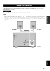
... on the rear panel of this unit until all cable connections are completed. Right speaker MAINS Speaker cables Left speaker TUNER FM ANT 75 UNBAL SUBWOOFER OUT SPEAKERS R L Rear panel English 9 En This could damage this unit. Notes • Be sure to the owner's manual supplied for the speakers. PREPARATION CONNECTING...
... on the rear panel of this unit until all cable connections are completed. Right speaker MAINS Speaker cables Left speaker TUNER FM ANT 75 UNBAL SUBWOOFER OUT SPEAKERS R L Rear panel English 9 En This could damage this unit. Notes • Be sure to the owner's manual supplied for the speakers. PREPARATION CONNECTING...
Owners Manual
Page 14
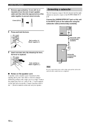
...One cable is replaced. Connect the plain cable to the "+"(red) terminals on the subwoofer using the subwoofer cable (commercially available). Note Do not connect the power cable of this unit and the subwoofer until all cable connections are mixed to the INPUT jack on this unit and your ...running side by side. By releasing the lever, the lever is colored or shaped differently, perhaps with a stripe, groove or ridge. Connect the SUBWOOFER OUT jack on this unit and your speaker. CONNECTING SPEAKERS 1 Remove approximately 10 mm (3/8 in) of insulation from the end of each speaker...
...One cable is replaced. Connect the plain cable to the "+"(red) terminals on the subwoofer using the subwoofer cable (commercially available). Note Do not connect the power cable of this unit and the subwoofer until all cable connections are mixed to the INPUT jack on this unit and your ...running side by side. By releasing the lever, the lever is colored or shaped differently, perhaps with a stripe, groove or ridge. Connect the SUBWOOFER OUT jack on this unit and your speaker. CONNECTING SPEAKERS 1 Remove approximately 10 mm (3/8 in) of insulation from the end of each speaker...
Owners Manual
Page 15
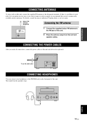
... on the front panel of this unit. Indoor FM antenna (supplied) Connecting the FM antenna TUNER FM ANT 75 UNBAL SUBWOOFER OUT 1 Connect the supplied indoor FM antenna to the FM jack of this unit. 2 Place the antenna away from ...the speakers stops. MAINS To an AC wall outlet TUNER FM ANT 75 UNBAL SUBWOOFER OUT SPEAKERS R L 6 MIN. CONNECTING THE POWER CABLES After you made all connections, connect the power cables of this unit...the PHONES jack on this unit and speaker cables. For details, consult the nearest authorized Yamaha dealer or service center.
... on the front panel of this unit. Indoor FM antenna (supplied) Connecting the FM antenna TUNER FM ANT 75 UNBAL SUBWOOFER OUT 1 Connect the supplied indoor FM antenna to the FM jack of this unit. 2 Place the antenna away from ...the speakers stops. MAINS To an AC wall outlet TUNER FM ANT 75 UNBAL SUBWOOFER OUT SPEAKERS R L 6 MIN. CONNECTING THE POWER CABLES After you made all connections, connect the power cables of this unit...the PHONES jack on this unit and speaker cables. For details, consult the nearest authorized Yamaha dealer or service center.