
Installation Guide
Page 2
... Application / Data Name YAMAHA USB MIDI Driver (for Win98, Me) YAMAHA USB MIDI Driver (for Win2000, XP) Digital Music Notebook Sample Songs for Digital Music Notebook Digital Music Notebook Flash Demo Musicsoft Downloader Sample songs Contents This software is an educational content that your CD player/ audio speakers. If you enjoy music while learning. Never attempt to page 3 for Windows Installation Guide Operating System (OS) The applications in versions for Windows" into the CD-ROM drive of the Digital Music Notebook...
... Application / Data Name YAMAHA USB MIDI Driver (for Win98, Me) YAMAHA USB MIDI Driver (for Win2000, XP) Digital Music Notebook Sample Songs for Digital Music Notebook Digital Music Notebook Flash Demo Musicsoft Downloader Sample songs Contents This software is an educational content that your CD player/ audio speakers. If you enjoy music while learning. Never attempt to page 3 for Windows Installation Guide Operating System (OS) The applications in versions for Windows" into the CD-ROM drive of the Digital Music Notebook...
Installation Guide
Page 3
... the window indicates the application or data contained in the software.) • During Demo mode. • During song playing back (depending on the model). • During Record mode. • During song editing (if the model has song edit function). • While songs, which explains the details about Digital Music Notebook is required to purchase/download song data from the dedicated Internet site, please use only the Musicsoft Downloader as File Utility and Song Filer...
... the window indicates the application or data contained in the software.) • During Demo mode. • During song playing back (depending on the model). • During Record mode. • During song editing (if the model has song edit function). • While songs, which explains the details about Digital Music Notebook is required to purchase/download song data from the dedicated Internet site, please use only the Musicsoft Downloader as File Utility and Song Filer...

Installation Guide
Page 4
...-ROM into the CD-ROM drive. 4 First, make sure the POWER switch on the instrument is ready for Windows Installation Guide The system starts the installation. 8 When installation is complete, the system displays "Completing the Found New Hardware Wizard." When the instrument is listed, and click [Next]. The window that transfers MIDI data back and forth between sequence software and the instrument via USB, you to select a location in...
...-ROM into the CD-ROM drive. 4 First, make sure the POWER switch on the instrument is ready for Windows Installation Guide The system starts the installation. 8 When installation is complete, the system displays "Completing the Found New Hardware Wizard." When the instrument is listed, and click [Next]. The window that transfers MIDI data back and forth between sequence software and the instrument via USB, you to select a location in...
Installation Guide
Page 5
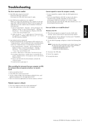
...\YAMAHA***.INF • \WINDOWS\SYSTEM\Xgusb.drv • \WINDOWS\SYSTEM\Ymidusb.sys 4 Disconnect the USB cable. 5 Restart the computer. 6 Re-install the driver. n To delete these files using Windows 2000/XP, you may be disabled. or "x" mark, the USB controller is heard. • Did you install the driver? • Is the USB cable connected correctly? • Are the volume settings of the instrument, playback device, and application program set to delete...
...\YAMAHA***.INF • \WINDOWS\SYSTEM\Xgusb.drv • \WINDOWS\SYSTEM\Ymidusb.sys 4 Disconnect the USB cable. 5 Restart the computer. 6 Re-install the driver. n To delete these files using Windows 2000/XP, you may be disabled. or "x" mark, the USB controller is heard. • Did you install the driver? • Is the USB cable connected correctly? • Are the volume settings of the instrument, playback device, and application program set to delete...
Installation Guide
Page 18
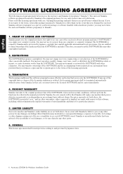
... the functions described in the manual provided by Japanese copyright laws and all terms outlined herein. PRODUCT WARRANTY Yamaha warrants to the original purchaser for use it on a single-user computer system. LIMITED LIABILITY Your sole remedies and Yamaha's entire liability are as set forth above . In no event will replace any other copyrighted materials. 2. RESTRICTIONS The SOFTWARE program is...
... the functions described in the manual provided by Japanese copyright laws and all terms outlined herein. PRODUCT WARRANTY Yamaha warrants to the original purchaser for use it on a single-user computer system. LIMITED LIABILITY Your sole remedies and Yamaha's entire liability are as set forth above . In no event will replace any other copyrighted materials. 2. RESTRICTIONS The SOFTWARE program is...
Service Manual
Page 2
... or other electrical/electronic and/or plastic (Where applicable) components may have therefore not been restated. KB-280 IMPORTANT NOTICE This manual has been provided for the use of this bus.) IMPORTANT : Turn the unit OFF during disassembly and parts replacement. The research engineering, and service departments of chemicals found by the users, and have accumulated by an authorized Yamaha Retailer or...
... or other electrical/electronic and/or plastic (Where applicable) components may have therefore not been restated. KB-280 IMPORTANT NOTICE This manual has been provided for the use of this bus.) IMPORTANT : Turn the unit OFF during disassembly and parts replacement. The research engineering, and service departments of chemicals found by the users, and have accumulated by an authorized Yamaha Retailer or...
Service Manual
Page 7
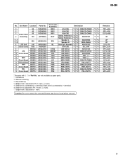
...parts with "( )" in "Part No." Black wire is connected to (-) terminal. *6: Red wire is adjusted to Pin 1 mark ( mark). *7: Edge mark is connected...parts. *1: Installation *2: Manual soldering *3: Dip soldering *4: Edge mark is adjusted to Pin 1 mark ( mark). *5: Red wire is adjusted to (+) terminal. Unit Name Location Parts No. q 30 w 40 e Lower Case 50 r Assembly 130 WC601200 WG343000 WC601000 (V873560) t-1 t-2 y LCD Unit u Keyboard Assembly i o AM !0 Circuit Board !1 !2 MIDI !3 Circuit Board !4 PB Circuit Board !5 PNR !6 Circuit Board !7 PNL !8 Circuit Board...
...parts with "( )" in "Part No." Black wire is connected to (-) terminal. *6: Red wire is adjusted to Pin 1 mark ( mark). *7: Edge mark is connected...parts. *1: Installation *2: Manual soldering *3: Dip soldering *4: Edge mark is adjusted to Pin 1 mark ( mark). *5: Red wire is adjusted to (+) terminal. Unit Name Location Parts No. q 30 w 40 e Lower Case 50 r Assembly 130 WC601200 WG343000 WC601000 (V873560) t-1 t-2 y LCD Unit u Keyboard Assembly i o AM !0 Circuit Board !1 !2 MIDI !3 Circuit Board !4 PB Circuit Board !5 PNR !6 Circuit Board !7 PNL !8 Circuit Board...
Service Manual
Page 10
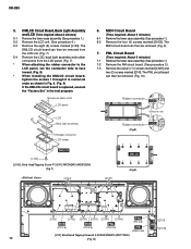
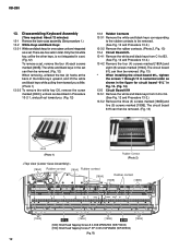
... the four (4) screws marked [210G]. KB-280 5. DMLCD Circuit Board, Back Light Assembly and LCD (Time required: About 4 minutes) 5-1 Remove the lower case assembly. (See procedure 1.) 5-2 Remove the LCD unit. (See procedure 4.) 5-3 Remove the eight (8) screws marked [L100]. The MIDI circuit board can then be removed. (Fig. 10) Nonwoven fabric cloth LCD panel LCD Back light assembly Rubber...
... the four (4) screws marked [210G]. KB-280 5. DMLCD Circuit Board, Back Light Assembly and LCD (Time required: About 4 minutes) 5-1 Remove the lower case assembly. (See procedure 1.) 5-2 Remove the LCD unit. (See procedure 4.) 5-3 Remove the eight (8) screws marked [L100]. The MIDI circuit board can then be removed. (Fig. 10) Nonwoven fabric cloth LCD panel LCD Back light assembly Rubber...
Service Manual
Page 11
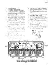
... Circuit Board and Speakers (Tweeters) (Time required: About 2 minutes each ) 10-1 Remove the lower case assembly. (See procedure 1.) [200A] 10-2 * Set the eight (8) hooks [A] parallel to the groove in the upper case assembly and remove the SP grille L. (Fig. 1, 5) The speaker grille R can then be removed. (Fig. 5) 9-2-2 TWR Circuit Board and Speaker R (Tweeter) Remove the TW3 connector assembly and speaker cable...
... Circuit Board and Speakers (Tweeters) (Time required: About 2 minutes each ) 10-1 Remove the lower case assembly. (See procedure 1.) [200A] 10-2 * Set the eight (8) hooks [A] parallel to the groove in the upper case assembly and remove the SP grille L. (Fig. 1, 5) The speaker grille R can then be removed. (Fig. 5) 9-2-2 TWR Circuit Board and Speaker R (Tweeter) Remove the TW3 connector assembly and speaker cable...
Service Manual
Page 12
...Keyboard Assembly (Time required: About 12 minutes) 13-1 Remove the lower case assembly. (See procedure 1.) 13-2 White Keys and Black Keys: 13-2-1 White and black keys for circuit board "61L" in total. The circuit board 61L can then be removed. (Fig. 12) When removing, unfasten the two (2) hooks at the back of the black keys...Fig. 13) * When installing the circuit board 61L, tighten the screws 1 through 12 in numerical order as shown in the figure for one octave unit are five sets in Fig. 14. (Fig. 14) 13-5 Circuit Board 61H 13-5-1 Remove the white and black keys from C1 to C6. ...
...Keyboard Assembly (Time required: About 12 minutes) 13-1 Remove the lower case assembly. (See procedure 1.) 13-2 White Keys and Black Keys: 13-2-1 White and black keys for circuit board "61L" in total. The circuit board 61L can then be removed. (Fig. 12) When removing, unfasten the two (2) hooks at the back of the black keys...Fig. 13) * When installing the circuit board 61L, tighten the screws 1 through 12 in numerical order as shown in the figure for one octave unit are five sets in Fig. 14. (Fig. 14) 13-5 Circuit Board 61H 13-5-1 Remove the white and black keys from C1 to C6. ...

Service Manual
Page 14
... FUNCTION Ground Power supply +3.3 V External memory lower-byte enable / Port F External memory upper-byte enable / Port F External memory read enable / Port F External memory data bus Ground External memory data bus Ground Power supply +2.5 V Power supply +3.3 V External memory address bus Ground External memory address bus External memory chip select / Port G External memory address bus External memory address bus / Port F External memory address bus External memory address bus / Port F External memory chip select / Port G External memory address bus / Port F Ground Power supply +2.5 V Power...
... FUNCTION Ground Power supply +3.3 V External memory lower-byte enable / Port F External memory upper-byte enable / Port F External memory read enable / Port F External memory data bus Ground External memory data bus Ground Power supply +2.5 V Power supply +3.3 V External memory address bus Ground External memory address bus External memory chip select / Port G External memory address bus External memory address bus / Port F External memory address bus External memory address bus / Port F External memory chip select / Port G External memory address bus / Port F Ground Power supply +2.5 V Power...

Service Manual
Page 15
... LCD driver output Display data interface Read/write Enable Data interface Data interface PIN NO. KB-280 NT3881DFG-01 (X3148A00) LCD DRIVER ML9040A-B01GAZ03A (XZ987A00) LCD DRIVER PIN NO. NAME I/O 41 DB2 I/O 42 DB3 I/O 43 DB4 I/O 44 DB5 I/O 45 DB6 I/O 46 DB7 I DMLCD: IC801 FUNCTION Analog input Digital data input Digital data output Digital clock input 15 NAME I/O 1 CS I 2 VA - 3 GND - 4 AIN4 I/O 5 AIN3 I /O FUNCTION Segment signal output for LCD driving Ground Oscillator Oscillator Power supply Data...
... LCD driver output Display data interface Read/write Enable Data interface Data interface PIN NO. KB-280 NT3881DFG-01 (X3148A00) LCD DRIVER ML9040A-B01GAZ03A (XZ987A00) LCD DRIVER PIN NO. NAME I/O 41 DB2 I/O 42 DB3 I/O 43 DB4 I/O 44 DB5 I/O 45 DB6 I/O 46 DB7 I DMLCD: IC801 FUNCTION Analog input Digital data input Digital data output Digital clock input 15 NAME I/O 1 CS I 2 VA - 3 GND - 4 AIN4 I/O 5 AIN3 I /O FUNCTION Segment signal output for LCD driving Ground Oscillator Oscillator Power supply Data...
Service Manual
Page 26
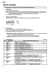
... a key to play a sound. (Single note, the key pressed first will be shown. KB-280 TEST PROGRAM ∗ If the test number 47 "Factory Set" is executed, the data already set will be lost. 1 Preparations 1) Use an AC adaptor PA-5D (PA-51). 2) Measuring device: Frequency counter, which the test results are NG, press the lowest key (white key C1) to return to the item selection display. 4 Test program list...
... a key to play a sound. (Single note, the key pressed first will be shown. KB-280 TEST PROGRAM ∗ If the test number 47 "Factory Set" is executed, the data already set will be lost. 1 Preparations 1) Use an AC adaptor PA-5D (PA-51). 2) Measuring device: Frequency counter, which the test results are NG, press the lowest key (white key C1) to return to the item selection display. 4 Test program list...
Service Manual
Page 27
... Item List on the next page.) When a switch with a MIDI cable and then execute the test. LCD display 9 SW Chk 020 10 A. When a switch is pressed, a sound is played at the prescribed pitch. (Refer to the play mode. 27 To cancel the operation halfway, press the lowest key (white key C1) to return to the [Exp. Make sure that "PB OK" is displayed on the LCD. Connect...
... Item List on the next page.) When a switch with a MIDI cable and then execute the test. LCD display 9 SW Chk 020 10 A. When a switch is pressed, a sound is played at the prescribed pitch. (Refer to the play mode. 27 To cancel the operation halfway, press the lowest key (white key C1) to return to the [Exp. Make sure that "PB OK" is displayed on the LCD. Connect...
Service Manual
Page 28
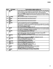
.... KB-280 Switch test item list Turn 1 2 3 4 5 6 7 8 9 10 11 12 13 14 15 16 17 18 19 20 21 22 23 24 25 26 27 28 29 30 31 32 33 34 35 36 SW Name Acmp Vol Acmp Vol Tempo Tempo Style AB 8Beat Ballad Rock Disco 1 Lou Gu Rumba Bossa March Waltz Metro4/4 Function +/Yes -/No TOUCH REVERB SUSTAIN Demo Voice AB DUAL SPLIT...
.... KB-280 Switch test item list Turn 1 2 3 4 5 6 7 8 9 10 11 12 13 14 15 16 17 18 19 20 21 22 23 24 25 26 27 28 29 30 31 32 33 34 35 36 SW Name Acmp Vol Acmp Vol Tempo Tempo Style AB 8Beat Ballad Rock Disco 1 Lou Gu Rumba Bossa March Waltz Metro4/4 Function +/Yes -/No TOUCH REVERB SUSTAIN Demo Voice AB DUAL SPLIT...
Service Manual
Page 30
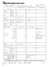
...,v=0 o 9nH,v=1-127 x After Key's x x Touch Ch's x x Pitch Bend Control Change o 0 - 24 semi o 0 - 24 semi 0,32 o 1,11 x 5,65,84 o 6,38 o 7,10 o 64 o 71-74 x 91,93 o 96-97 x 100-101 o o *1 o o o o o *1 o o *1 o o Date:17-NOV-2005 Version : 1.0 Remarks Bank Select Data Entry Sustain Sound Controller Effect Depth RPN Inc,Dec RPN LSB,MSB Prog Change : True # o 0 - 127 o 0 - 127 System Exclusive o o : Song Pos. x x Common : Song Sel. KB-280 MIDI IMPLEMENTATION CHART YAMAHA [ PortaTone ] Model KB-280 MIDI Implementation Chart Function...
...,v=0 o 9nH,v=1-127 x After Key's x x Touch Ch's x x Pitch Bend Control Change o 0 - 24 semi o 0 - 24 semi 0,32 o 1,11 x 5,65,84 o 6,38 o 7,10 o 64 o 71-74 x 91,93 o 96-97 x 100-101 o o *1 o o o o o *1 o o *1 o o Date:17-NOV-2005 Version : 1.0 Remarks Bank Select Data Entry Sustain Sound Controller Effect Depth RPN Inc,Dec RPN LSB,MSB Prog Change : True # o 0 - 127 o 0 - 127 System Exclusive o o : Song Pos. x x Common : Song Sel. KB-280 MIDI IMPLEMENTATION CHART YAMAHA [ PortaTone ] Model KB-280 MIDI Implementation Chart Function...
Service Manual
Page 34
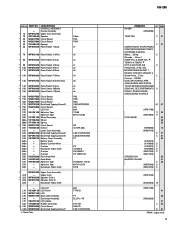
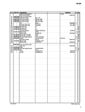
... 2 01 ACMP,SYNCRO STOP,SYNCRO START,INTRO/ENDING START/ STOP,MAIN A,MAIN B 8Beat,...,Swing, 2 Rhumba,...,China 1 ACMP VOL ,ACMP VOL , TEMPO ,TEMPO STYLE A/B,VOISE A/B 2 FUNCTION,+/YES,-/NO MEMORY,BANK,REGIST 1, REGIST 2,REGIST 3,REGIST 4 Grand Piano,...,Flute, 2 Clarinet,...,SE/GM DUAL,SPLIT,ERHU1,PIPA, JINHU,ZHENG,XIAO,SUONA TOUCH,REVERB,SUSTAIN,DEMO SONG NO.,REC,PORTAMENTO 3 SONG 1,SONG2,SONG3, SNOG4,SONG 5,SONG A 61 01 PITCH BEND (WF81700) 11 03 (WB79380...
... 2 01 ACMP,SYNCRO STOP,SYNCRO START,INTRO/ENDING START/ STOP,MAIN A,MAIN B 8Beat,...,Swing, 2 Rhumba,...,China 1 ACMP VOL ,ACMP VOL , TEMPO ,TEMPO STYLE A/B,VOISE A/B 2 FUNCTION,+/YES,-/NO MEMORY,BANK,REGIST 1, REGIST 2,REGIST 3,REGIST 4 Grand Piano,...,Flute, 2 Clarinet,...,SE/GM DUAL,SPLIT,ERHU1,PIPA, JINHU,ZHENG,XIAO,SUONA TOUCH,REVERB,SUSTAIN,DEMO SONG NO.,REC,PORTAMENTO 3 SONG 1,SONG2,SONG3, SNOG4,SONG 5,SONG A 61 01 PITCH BEND (WF81700) 11 03 (WB79380...
Service Manual
Page 38
... 380X15X1.0 PE 885X15X1.0 KB-280 KB-280 REMARKS QTY RANK (WG07410) WOOFER (WC62030) 2 (V771130) 6 (V771140) 01 01 5 01 (V873560) 11 03 (WB79380) 11 05 05 40 01 2 06 (WG32410) 2 03 (WB79390) (WG07390) 3 6 01 5 01 (V881260) 2 (V642110) : New Parts RANK: Japan only 7 Lower Case Assembly 10 WG074000 Lower Case Sub Assembly 20 V 8 6 9 5 7 0 0 Keyboard Assembly 30 WC601200 Connector...
... 380X15X1.0 PE 885X15X1.0 KB-280 KB-280 REMARKS QTY RANK (WG07410) WOOFER (WC62030) 2 (V771130) 6 (V771140) 01 01 5 01 (V873560) 11 03 (WB79380) 11 05 05 40 01 2 06 (WG32410) 2 03 (WB79390) (WG07390) 3 6 01 5 01 (V881260) 2 (V642110) : New Parts RANK: Japan only 7 Lower Case Assembly 10 WG074000 Lower Case Sub Assembly 20 V 8 6 9 5 7 0 0 Keyboard Assembly 30 WC601200 Connector...

Service Manual
Page 46
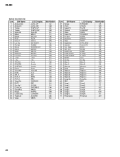
...LED AIN1 LED CN7855 (3P) CN777 (3P) KB-280 BLOCK DIAGRAM TOUCH RESPONSE Keybord 61KEY (16N) 61L (C1~B3) PC0-5,PD0-5 SW1-36 61H (C4~C6) PC0-5,PD0-5 SW37-61 PB (AMJK 6/6) VR751 PITCH BEND PNL (PN 4/6) SW771 PA6 PB6 LED LD753...adaptor PA-5C/PA-5D/PA-51 4 BATTERY 1.5V x 6 CN154 (4P) CN153 (4P) CN151 (3P) MIDI OUT IN SUSTAIN JK852 JK853 JK851 I/F IC851,TR851,852 RXD0 TXD0 PC7 IRQ0 DGND R+ R- MIDI (AMJK 2/6) CN555 (2P) CN556 (2P) AM (AMJK 5/6) SW151 STANDBY/ON + TWR (PN 5/6,6/6) DGND TWEETER R EXPRESSION JK856 5 WOOFER R 4Ω 12cm KB-280 BLOCK DIAGRAM 6 L 11 L+ 1 POWER AMP...
...LED AIN1 LED CN7855 (3P) CN777 (3P) KB-280 BLOCK DIAGRAM TOUCH RESPONSE Keybord 61KEY (16N) 61L (C1~B3) PC0-5,PD0-5 SW1-36 61H (C4~C6) PC0-5,PD0-5 SW37-61 PB (AMJK 6/6) VR751 PITCH BEND PNL (PN 4/6) SW771 PA6 PB6 LED LD753...adaptor PA-5C/PA-5D/PA-51 4 BATTERY 1.5V x 6 CN154 (4P) CN153 (4P) CN151 (3P) MIDI OUT IN SUSTAIN JK852 JK853 JK851 I/F IC851,TR851,852 RXD0 TXD0 PC7 IRQ0 DGND R+ R- MIDI (AMJK 2/6) CN555 (2P) CN556 (2P) AM (AMJK 5/6) SW151 STANDBY/ON + TWR (PN 5/6,6/6) DGND TWEETER R EXPRESSION JK856 5 WOOFER R 4Ω 12cm KB-280 BLOCK DIAGRAM 6 L 11 L+ 1 POWER AMP...

Service Manual
Page 47
... Proof C.Resistor XX : Not installed Note1 : See parts list for details of the part reference number. OUTPUT RH5RZ50CA-T1-F (X6959A00) REGULATOR +5V DMLCD: IC101 1 3 1. A B C D E KB-280 OVERALL CIRCUIT DIAGRAM (AM, DMLCD, MIDI, PB, PNL, PNR, TWL, TWR, 61H, 61L) 1 DMLCD F ROM 128M PROG./WAVE 2 3 4 5 XX 6 LCD DRIVER XX SYSTEM RESET CPU (USB) CPU (SWL01T) 7 to B-8 REGULATOR +3.3V XX POWER SUPPLY XX TRAD.ACD FR.HORN...
... Proof C.Resistor XX : Not installed Note1 : See parts list for details of the part reference number. OUTPUT RH5RZ50CA-T1-F (X6959A00) REGULATOR +5V DMLCD: IC101 1 3 1. A B C D E KB-280 OVERALL CIRCUIT DIAGRAM (AM, DMLCD, MIDI, PB, PNL, PNR, TWL, TWR, 61H, 61L) 1 DMLCD F ROM 128M PROG./WAVE 2 3 4 5 XX 6 LCD DRIVER XX SYSTEM RESET CPU (USB) CPU (SWL01T) 7 to B-8 REGULATOR +3.3V XX POWER SUPPLY XX TRAD.ACD FR.HORN...


