
Owner's Manual
Page 2
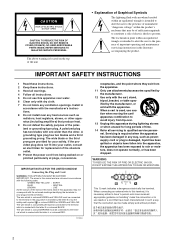
..., heat registers, stoves, or other . NO USER-SERVICEABLE PARTS INSIDE. IMPORTANT SAFETY INSTRUCTIONS 1 Read these instructions. 2 Keep these instructions. 3 Heed all warnings. 4 Follow all servicing to rain or moisture, does not operate normally, or has been dropped. The wide blade...code: GREEN-AND-YELLOW : EARTH BLUE : NEUTRAL BROWN : LIVE As the colours of the wires in the mains lead of time. 14 Refer all instructions. 5 Do not use this apparatus near water. 6 Clean only with the manufacturer's instructions. 8 Do not install near any heat sources such as powersupply cord or plug...
..., heat registers, stoves, or other . NO USER-SERVICEABLE PARTS INSIDE. IMPORTANT SAFETY INSTRUCTIONS 1 Read these instructions. 2 Keep these instructions. 3 Heed all warnings. 4 Follow all servicing to rain or moisture, does not operate normally, or has been dropped. The wide blade...code: GREEN-AND-YELLOW : EARTH BLUE : NEUTRAL BROWN : LIVE As the colours of the wires in the mains lead of time. 14 Refer all instructions. 5 Do not use this apparatus near water. 6 Clean only with the manufacturer's instructions. 8 Do not install near any heat sources such as powersupply cord or plug...
Owner's Manual
Page 3
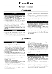
... AC outlet, and remove all musical instruments, audio equipment, and speakers when connecting to this unit for normal ventilation. Locations exposed to excessive heat, such as possible, and unplug the power cable plug from the AC outlet. Locations subject to excessive humidity or dust accumulation. ● Do not place the power cord close to amplifier outputs. place the unit on top...
... AC outlet, and remove all musical instruments, audio equipment, and speakers when connecting to this unit for normal ventilation. Locations exposed to excessive heat, such as possible, and unplug the power cable plug from the AC outlet. Locations subject to excessive humidity or dust accumulation. ● Do not place the power cord close to amplifier outputs. place the unit on top...
Owner's Manual
Page 4
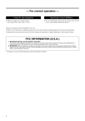
... YAMAHA CORPORATION OF AMERICA. 4 IMPORTANT: When connecting this Owner's Manual are wired as indicated in the instructions contained in this unit may void your FCC authorization to accessories and/or another product use this product MUST be used in use the product. 2. - Always turn the power off when the amplifier is not in this product to use only high quality shielded cables. For correct operation...
... YAMAHA CORPORATION OF AMERICA. 4 IMPORTANT: When connecting this Owner's Manual are wired as indicated in the instructions contained in this unit may void your FCC authorization to accessories and/or another product use this product MUST be used in use the product. 2. - Always turn the power off when the amplifier is not in this product to use only high quality shielded cables. For correct operation...
Owner's Manual
Page 5
... trouble-free operation for a wide variety of the YAMAHA KAX-5000, KAX3500 or KAX-2500 power amplifier. The TEMP indicator lights up -and sound output is automatically muted-whenever the unit's protective circuitry is running hot. • Variable-speed low-noise fans ensure high reliability. Contents Controls and Functions 6 Front Panel 6 Rear Panel 7 Speaker Connections 9 Speaker impedance 9 Wiring 10 Rack Mounting 11 Specifications 12 General Specifications 12 Block Diagram 13 Dimensions 14 Current Draw 14 Troubleshooting 15 5 This Owner's Manual...
... trouble-free operation for a wide variety of the YAMAHA KAX-5000, KAX3500 or KAX-2500 power amplifier. The TEMP indicator lights up -and sound output is automatically muted-whenever the unit's protective circuitry is running hot. • Variable-speed low-noise fans ensure high reliability. Contents Controls and Functions 6 Front Panel 6 Rear Panel 7 Speaker Connections 9 Speaker impedance 9 Wiring 10 Rack Mounting 11 Specifications 12 General Specifications 12 Block Diagram 13 Dimensions 14 Current Draw 14 Troubleshooting 15 5 This Owner's Manual...
Owner's Manual
Page 6
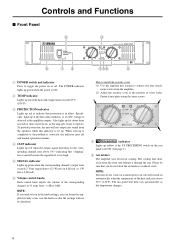
... problem is too high. 5 SIGNAL indicator Lights up green when the corresponding channel's output level exceeds 2 Vrms (equivalent to 1/2 W into an 8 Ω load, or 1 W into place using the same screws. 7 indicator Lights up yellow if the YS PROCESSING switch on the rear panel is lit up. Also lights up for about three seconds at time of the heat sink rises above 1%-indicating that protection...
... problem is too high. 5 SIGNAL indicator Lights up green when the corresponding channel's output level exceeds 2 Vrms (equivalent to 1/2 W into an 8 Ω load, or 1 W into place using the same screws. 7 indicator Lights up yellow if the YS PROCESSING switch on the rear panel is lit up. Also lights up for about three seconds at time of the heat sink rises above 1%-indicating that protection...
Owner's Manual
Page 7
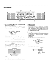
... enhance speaker output. Note that this switch is effective only if the FILTER switch is set this setting to filter out unneeded low or subsonic frequencies. If you select SUBWOOFER or LOW CUT, you set to OFF. 3 INPUT jacks (Channels A, B) Two jack types are wired as follows. Use a low-pass filter. You can then use this switch ON, the amplifier adds low-frequency compensation so as follows. ing to the speaker type. ■ Rear Panel 12 5 LOW CUT SUB WOOFER...
... enhance speaker output. Note that this switch is effective only if the FILTER switch is set this setting to filter out unneeded low or subsonic frequencies. If you select SUBWOOFER or LOW CUT, you set to OFF. 3 INPUT jacks (Channels A, B) Two jack types are wired as follows. Use a low-pass filter. You can then use this switch ON, the amplifier adds low-frequency compensation so as follows. ing to the speaker type. ■ Rear Panel 12 5 LOW CUT SUB WOOFER...
Owner's Manual
Page 8
... the Channel B output jacks. • PARALLEL mode The Channel A input signal is output from the BRIDGE output jacks. Channel A and B volumes can be independently adjusted. • BRIDGE mode The Channel A input signal is output through both the Channel A and Channel B output jacks. The Channel B input jacks do not function. To adjust the volume, you are having a problem with a conventional stereo amplifier). If you must use this switch to select the operating mode. • STEREO mode Channels A and B operate independently (as with hum or noise, use the Channel A volume control knob...
... the Channel B output jacks. • PARALLEL mode The Channel A input signal is output from the BRIDGE output jacks. Channel A and B volumes can be independently adjusted. • BRIDGE mode The Channel A input signal is output through both the Channel A and Channel B output jacks. The Channel B input jacks do not function. To adjust the volume, you are having a problem with a conventional stereo amplifier). If you must use this switch to select the operating mode. • STEREO mode Channels A and B operate independently (as with hum or noise, use the Channel A volume control knob...
Owner's Manual
Page 9
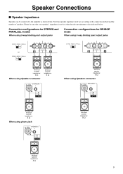
... + 2- - Speaker Connections ■ Speaker impedance Speakers can be sure that speaker impedance will vary according to the amplifier as shown below . Connection configurations for STEREO and PARALLEL modes When using 5-way binding post output jacks Connection configurations for BRIDGE mode When using 5-way binding post output jacks STEREO BRIDGE PARALLEL or STEREO BRIDGE PARALLEL - 1+ +1- (-) (+) BRIDGE STEREO BRIDGE PARALLEL - 1+ +1- (-) (+) BRIDGE Minimum speaker impedance: 4 Ω When using Speakon connector Minimum speaker impedance: 4 Ω LOCK LOCK SPEAKERS...
... + 2- - Speaker Connections ■ Speaker impedance Speakers can be sure that speaker impedance will vary according to the amplifier as shown below . Connection configurations for STEREO and PARALLEL modes When using 5-way binding post output jacks Connection configurations for BRIDGE mode When using 5-way binding post output jacks STEREO BRIDGE PARALLEL or STEREO BRIDGE PARALLEL - 1+ +1- (-) (+) BRIDGE STEREO BRIDGE PARALLEL - 1+ +1- (-) (+) BRIDGE Minimum speaker impedance: 4 Ω When using Speakon connector Minimum speaker impedance: 4 Ω LOCK LOCK SPEAKERS...
Owner's Manual
Page 10
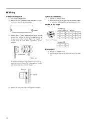
... insulation from the end of the amplifier, and turn clockwise to lock. Neutrik NL4FC plugs CHANNEL B 1+ B+ 1- Phone jack (1) Turn off the POWER switch. (2) Insert the phone plug into the Speakon connec- fier. Bare wire Chassis (4) Reattach the protective cover over the speaker terminals. 10 Neutrik NL4FC plugs CHANNEL A STEREO or PARALLEL BRIDGE 1+ A+ 1+ + 1- B- A- 1- 2+ B+ 2+ - 2- Tighten the terminals to page 9 for speaker polarities. * Speaker cable * Actual size Be sure that the...
... insulation from the end of the amplifier, and turn clockwise to lock. Neutrik NL4FC plugs CHANNEL B 1+ B+ 1- Phone jack (1) Turn off the POWER switch. (2) Insert the phone plug into the Speakon connec- fier. Bare wire Chassis (4) Reattach the protective cover over the speaker terminals. 10 Neutrik NL4FC plugs CHANNEL A STEREO or PARALLEL BRIDGE 1+ A+ 1+ + 1- B- A- 1- 2+ B+ 2+ - 2- Tighten the terminals to page 9 for speaker polarities. * Speaker cable * Actual size Be sure that the...
Owner's Manual
Page 11
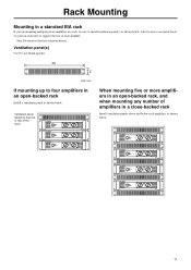
... install ventilation panel(s) as shown below . Note: EIA stands for Electronic Industries Alliance. Ventilation panel(s) Use 1U-size blank panel(s). 480 44 Unit: mm If mounting up to the front or rear of the rack.) When mounting five or more amplifiers in an open -backed rack Install a ventilation panel as shown below . Also be sure to support the rear of each amplifier...
... install ventilation panel(s) as shown below . Note: EIA stands for Electronic Industries Alliance. Ventilation panel(s) Use 1U-size blank panel(s). 480 44 Unit: mm If mounting up to the front or rear of the rack.) When mounting five or more amplifiers in an open -backed rack Install a ventilation panel as shown below . Also be sure to support the rear of each amplifier...
Owner's Manual
Page 12
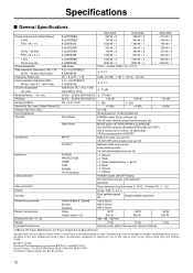
... wrench), Owner's Manual 25 W 320 W 14 kg 0 dBu=0.775 Vrms, Half Power=1/2 Power Output Level (Rated Power) Specifications and descriptions in EN55103-1 and EN55103-2. max.) 32.1 dB Input Impedance 30 kΩ/balanced, 15 kΩ/unbalanced Controls Front Panel POWER switch (Push on/Push off) Two 31-step Volume control knobs (one per ch) 650 W × 2 1300 W × 1 100 dB +3 dBu Connectors Rear Panel INPUT MODE switch (STEREO/PARALLEL/BRIDGE) Two FILTER switches (SUBWOOFER/LOW CUT/OFF...
... wrench), Owner's Manual 25 W 320 W 14 kg 0 dBu=0.775 Vrms, Half Power=1/2 Power Output Level (Rated Power) Specifications and descriptions in EN55103-1 and EN55103-2. max.) 32.1 dB Input Impedance 30 kΩ/balanced, 15 kΩ/unbalanced Controls Front Panel POWER switch (Push on/Push off) Two 31-step Volume control knobs (one per ch) 650 W × 2 1300 W × 1 100 dB +3 dBu Connectors Rear Panel INPUT MODE switch (STEREO/PARALLEL/BRIDGE) Two FILTER switches (SUBWOOFER/LOW CUT/OFF...
Owner's Manual
Page 14
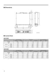
■ Dimensions ■ Current Draw KAX-5000 standby idle 1/8 power 8Ω/ch 4Ω/ch 1/3 power 8Ω/ch 4Ω/ch KAX-3500 standby idle 1/8 power 8Ω/ch 4Ω/ch 1/3 power 8Ω/ch 4Ω/ch Line Current (A) 100/120V 230/240V 0.08 0.04 1.0 0.5 4.0 2.2 6.2 3.4 9.3 5.1 14.7 8.1 Line Current (A) 100/120V 230/240V 0.08 0.04 1.0 0.5 3.2 1.7 5.0 2.8 7.3 4.0 12.2 6.7 Unit: mm In 5 ...
■ Dimensions ■ Current Draw KAX-5000 standby idle 1/8 power 8Ω/ch 4Ω/ch 1/3 power 8Ω/ch 4Ω/ch KAX-3500 standby idle 1/8 power 8Ω/ch 4Ω/ch 1/3 power 8Ω/ch 4Ω/ch Line Current (A) 100/120V 230/240V 0.08 0.04 1.0 0.5 4.0 2.2 6.2 3.4 9.3 5.1 14.7 8.1 Line Current (A) 100/120V 230/240V 0.08 0.04 1.0 0.5 3.2 1.7 5.0 2.8 7.3 4.0 12.2 6.7 Unit: mm In 5 ...
Owner's Manual
Page 15
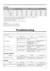
... nearest Yamaha service center. Possible Cause Remedy Protection Circuit There is a short at least 4 Ω (STEREO/PARALLEL mode) or 8 Ω (BRIDGE mode). The relay operates to indicate temperature warning. The protection circuitry shut off .) A DC voltage of ± 2 V or greater was generated in the power amplifier's output circuit. The PC limiter circuit operates to protect the speaker system. 15 KAX-3500, KAX-2500 Indicator(s) PROTECTION indicator lights. Possible Cause Remedy Protection Circuit...
... nearest Yamaha service center. Possible Cause Remedy Protection Circuit There is a short at least 4 Ω (STEREO/PARALLEL mode) or 8 Ω (BRIDGE mode). The relay operates to indicate temperature warning. The protection circuitry shut off .) A DC voltage of ± 2 V or greater was generated in the power amplifier's output circuit. The PC limiter circuit operates to protect the speaker system. 15 KAX-3500, KAX-2500 Indicator(s) PROTECTION indicator lights. Possible Cause Remedy Protection Circuit...


