Yamaha KAX-5000 Support and Manuals
Get Help and Manuals for this Yamaha item

View All Support Options Below
Free Yamaha KAX-5000 manuals!
Problems with Yamaha KAX-5000?
Ask a Question
Free Yamaha KAX-5000 manuals!
Problems with Yamaha KAX-5000?
Ask a Question
Popular Yamaha KAX-5000 Manual Pages
Owner's Manual - Page 2
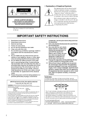
... outlet. 10 Protect the power cord from tip-over. 13 Unplug this mains lead are provided for long periods of important operating and maintenance (servicing) instructions in
accordance with the manufacturer's instructions. 8 Do not install near water. 6 Clean only with the apparatus. IMPORTANT SAFETY INSTRUCTIONS
1 Read these instructions. 2 Keep these instructions. 3 Heed all warnings...
Owner's Manual - Page 3
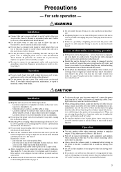
..., including this unit. When you think internal inspection, maintenance, or repair is a fire and electrical shock hazard. A damaged power cord is necessary, contact your hearing.
● Do not use this instruction, fire or electrical shock may cause fire or electrical shock.
● When setting up inside this unit are using is a fire and electrical...
Owner's Manual - Page 4
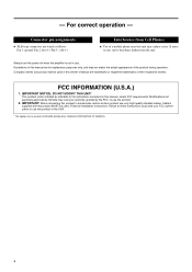
... wired as indicated in the instructions contained in this manual are trademarks or registered trademarks of their respective owners. Illustrations in this unit may void your FCC authorization to products (KAX-5000) distributed by Yamaha may induce noise. This product, when installed as follows Pin 1: ground; Always turn the power off when the amplifier is not in use...
Owner's Manual - Page 5
...sized package.
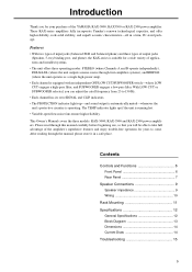
This Owner's Manual covers the three models: KAX-5000, KAX-3500 and KAX-2500 power amplifiers. With LOW CUT or SUBWOOFER selected, you can adjust the cutoff frequency from 25 to come. Introduction
Thank you for your purchase of the amplifier's superlative features and enjoy trouble-free operation for a wide variety of applications and installed systems.
• The unit...
Owner's Manual - Page 6
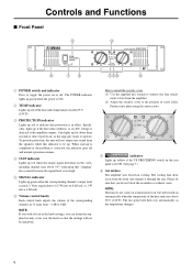
... 7.)
8 Air intakes The amplifier uses forced-air cooling. The POWER indicator lights up green when the power is ON.
2 TEMP indicator Lights up red if the heat sink temperature exceeds 85°C (185°F).
3 PROTECTION indicator Lights up red to indicate that the settings will then vary automatically as the amp gets ready to lock...
Owner's Manual - Page 7
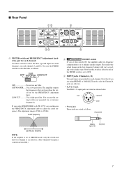
... select the filter type and adjust the cutoff frequency on each channel. ■ Rear Panel
12
5
LOW CUT
SUB WOOFER
OFF
OFF
SUB WOOFER
LOW CUT
90 50
125
ON OFF
90... below. SUBWOOFER..... You can then use this switch ON, the amplifier adds low-frequency
compensation so as follows. Note that are lower than the cutoff set to BRIDGE mode, only the switch and knob for Channel A ...
Owner's Manual - Page 8
... operating mode.
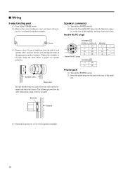
• STEREO mode Channels A and B operate independently (as with a conventional stereo amplifier). The Channel B input jacks do not function. 4 STEREO/PARALLEL/BRIDGE switch Use this terminal to connect... or to connect to the chassis of the mixer, preamp, or other device in your system.
8 To adjust the volume, you are having a problem with hum or noise, use the Channel A...
Owner's Manual - Page 9
...;
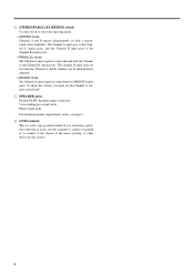
When using phone jack
LOCK
LOCK SPEAKERS
3
2
23
+ 1+ - 1-
1+ + 1- -
2+ + 2- -
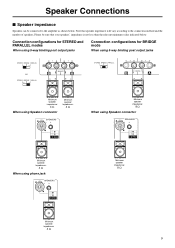
Speaker Connections
■ Speaker impedance
Speakers can be sure that speaker impedance will vary according to the amplifier as shown below . Please be connected to the connection method and the number of speakers. Minimum speaker impedance:
4 Ω
When using Speakon connector
Minimum speaker...
Owner's Manual - Page 10
... look when correctly attached.
Neutrik NL4FC plugs
CHANNEL B
1+
B+
1- B- Screw
(3) Remove about 15 mm of the amplifier, and turn clockwise to securely clamp the wires. A-
1-
2+
B+
2+
-
2- B-
2-
tective cover from the speaker terminals.
Speakon connector
(1) Turn off the POWER switch. (2) Insert the Neutrik NL4FC plugs into the jack on the rear of insulation from the...
Owner's Manual - Page 11
..., and when mounting any number of each amplifier, as shown below each amplifer.
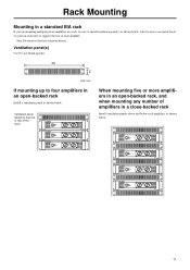
Rack Mounting
Mounting in a standard EIA rack
If you are mounting multiple power amplifiers in a rack, be sure to use metal brackets (one on each side) to support the rear of amplifiers in a close-backed rack
Install ventilation panels above and below .
11...
Owner's Manual - Page 12
... per ch)
Indicators
Load protection
Amp. detection (heat sink temp &#...12 kg
15 kg
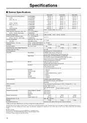
Security cover (with your Yamaha dealer. European models Purchaser/User Information specified in this owner's manual are for information purposes only. Specifications
■ General Specifications
Power Output Level (Rated Power) 1 kHz THD + N = 1%
8 Ω/STEREO 4 Ω/STEREO 8 Ω/BRIDGE
KAX-5000...
Owner's Manual - Page 14
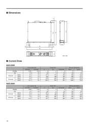
... Draw
KAX-5000
standby
idle
1/8 power
8Ω/ch 4Ω/ch
1/3 power
8Ω/ch 4Ω/ch
KAX-3500
standby
idle
1/8 power
8Ω/ch 4Ω/ch
1/3 power
8Ω/ch 4Ω/ch
Line Current (A)
100/120V
230/240V
0.08
0.04
1.0
0.5
4.0
2.2
6.2
3.4
9.3
5.1
14.7
8.1
Line Current (A)
100/120V
230/240V
0.08
0.04
1.0
0.5
3.2
1.7
5.0
2.8
7.3
4.0
12.2
6.7
Unit...
Owner's Manual - Page 15
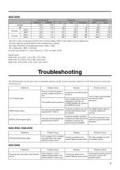
... to protect the power transistors. KAX-5000
Indicator(s)
Possible Cause
Remedy
Protection Circuit
Power has been shut down. (All indicators are off the power to [W].
TEMP indicator lights. The heat sink temperature has exceeded 85°C (185°F).
Consult your dealer or the nearest Yamaha service center. Refer to improve the airflow around the amplifier.
Check the...
Yamaha KAX-5000 Reviews
We have not received any reviews for Yamaha yet.