
Owner's Manual
Page 6
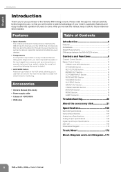
... for your purchase of the input signal from a source such as four stereo inputs that can compress the peaks of the Yamaha IM8 mixing console. Accessories • Owner's Manual (this manual carefully before beginning use them not only for the main mix but...can accommodate mic through this book) • Power supply cable • Cubase AI 4 DVD-ROM • USB cable Introduction 6 Features 6 Accessories 6 System Requirements 7 Differences between the IM8-40/32/24 mixers 7 Controls and Functions 8 Channel Control Section 8 Master Control Section 12 STEREO AUX RETURN Section ...
... for your purchase of the input signal from a source such as four stereo inputs that can compress the peaks of the Yamaha IM8 mixing console. Accessories • Owner's Manual (this manual carefully before beginning use them not only for the main mix but...can accommodate mic through this book) • Power supply cable • Cubase AI 4 DVD-ROM • USB cable Introduction 6 Features 6 Accessories 6 System Requirements 7 Differences between the IM8-40/32/24 mixers 7 Controls and Functions 8 Channel Control Section 8 Master Control Section 12 STEREO AUX RETURN Section ...

Owner's Manual
Page 12
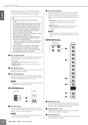
... OUT Section (page 14) STEREO AUX RETURN Section (page 13) GROUP OUT Section (page 16) DC POWER INPUT 2TR IN/USB Section (page 13) MONO Section (page 19) Top Panel 2TR IN/USB Section (page 13) STEREO MASTER Section (page 17) AUX SEND Section (page 16) DC POWER INPUT Section (page 15...) REC OUT/USB Section (page 14) MATRIX OUT Section (page 14) DC POWER INPUT Section (page 15) MUTE MASTER Section (page 15) TALKBACK Section (page 15) AUX SEND ...
... OUT Section (page 14) STEREO AUX RETURN Section (page 13) GROUP OUT Section (page 16) DC POWER INPUT 2TR IN/USB Section (page 13) MONO Section (page 19) Top Panel 2TR IN/USB Section (page 13) STEREO MASTER Section (page 17) AUX SEND Section (page 16) DC POWER INPUT Section (page 15...) REC OUT/USB Section (page 14) MATRIX OUT Section (page 14) DC POWER INPUT Section (page 15) MUTE MASTER Section (page 15) TALKBACK Section (page 15) AUX SEND ...

Owner's Manual
Page 13
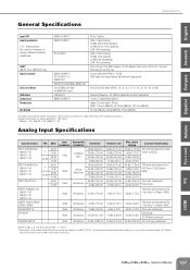
...Use these jacks can also be sent to the GROUP 1/ 2-7/8, ST L/R, MONO, and AUX 1-4 buses. When connecting or disconnecting the USB cable be mixed. 2 USB Connector Connects to the computer via the included cable to input and output the signals. These jacks are typically used as auxiliary stereo inputs... by the RETURN control. 2 Top Panel 3 4 5 1 2TR IN Jacks These are simultaneously input from these jacks when you turn the 2TR IN/USB control all the way down. The signal input from the AUX RETURN jacks to the GROUP 1/2-7/8, ST L/R, or MONO buses. This connector outputs the same...
...Use these jacks can also be sent to the GROUP 1/ 2-7/8, ST L/R, MONO, and AUX 1-4 buses. When connecting or disconnecting the USB cable be mixed. 2 USB Connector Connects to the computer via the included cable to input and output the signals. These jacks are typically used as auxiliary stereo inputs... by the RETURN control. 2 Top Panel 3 4 5 1 2TR IN Jacks These are simultaneously input from these jacks when you turn the 2TR IN/USB control all the way down. The signal input from the AUX RETURN jacks to the GROUP 1/2-7/8, ST L/R, or MONO buses. This connector outputs the same...
Owner's Manual
Page 14
... 2 GROUP Controls (1-8) These adjust the level of the signals sent from any open application software on again, or (2) when alternately connecting/disconnecting the USB cable. 2 Bus Assign Switches These switches determine the signal sent to which the sig- If you turn on /off . • Before connecting ... mode of the computer (such as suspended, sleep, standby). • Before turning on the power to the instrument, connect the computer to the USB connector. • Execute the following order; first the audio sources, then the PW8, and finally the power amplifiers....
... 2 GROUP Controls (1-8) These adjust the level of the signals sent from any open application software on again, or (2) when alternately connecting/disconnecting the USB cable. 2 Bus Assign Switches These switches determine the signal sent to which the sig- If you turn on /off . • Before connecting ... mode of the computer (such as suspended, sleep, standby). • Before turning on the power to the instrument, connect the computer to the USB connector. • Execute the following order; first the audio sources, then the PW8, and finally the power amplifiers....
Owner's Manual
Page 25
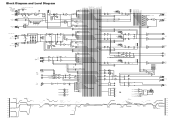
... (50.1 mV) -10 dBV (0.316 V) -66 dBu (0.389 mV) -50 dBu (2.45 mV) Max. LAMP IM8-40: 3 pcs, IM8-32/24: 2pcs Signal Indicator LED Level Meter USB Audio Compressor Dimensions Net Weight MONO CH INPUT* MONO CH INPUT* ST CH INPUT MONO CH INPUT* ST CH INPUT 1-4... of signal generator: 150 ohms * IM8-40: 1-40, IM8-32: 1-32, IM8-24: 1-24 Analog Input Specifications Input Connectors INPUT A (MONO CHs) IM8-40: 1-40 IM8-32: 1-32 IM8-40: 1-24 INPUT B (MONO CHs) IM8-40: 1-40 IM8-32: 1-32 IM8-40: 1-24 INPUT A/B (ST CHs) INSERT IN (MONO CHs) IM8-40: 1-40 IM8-32: 1-32 IM8-40: 1-24 INSERT IN (AUX, GROUP...
... (50.1 mV) -10 dBV (0.316 V) -66 dBu (0.389 mV) -50 dBu (2.45 mV) Max. LAMP IM8-40: 3 pcs, IM8-32/24: 2pcs Signal Indicator LED Level Meter USB Audio Compressor Dimensions Net Weight MONO CH INPUT* MONO CH INPUT* ST CH INPUT MONO CH INPUT* ST CH INPUT 1-4... of signal generator: 150 ohms * IM8-40: 1-40, IM8-32: 1-32, IM8-24: 1-24 Analog Input Specifications Input Connectors INPUT A (MONO CHs) IM8-40: 1-40 IM8-32: 1-32 IM8-40: 1-24 INPUT B (MONO CHs) IM8-40: 1-40 IM8-32: 1-32 IM8-40: 1-24 INPUT A/B (ST CHs) INSERT IN (MONO CHs) IM8-40: 1-40 IM8-32: 1-32 IM8-40: 1-24 INSERT IN (AUX, GROUP...

Owner's Manual
Page 26
...; Lines 600 Ω Lines 10 kΩ Lines 600 Ω Lines 10 kΩ Lines 10 kΩ Lines 10 kΩ Lines 10 kΩ Lines 10 kΩ Lines 40 Ω Phones Nominal Level +4 dBu (1.23 V) +4 dBu (1.23 V) +4 dBu (1.23 V) +4 dBu (1.23 V) +4 dBu (1.23 V) 0 dBu (0.775 V) 0 dBu (0.775 V) 0 dBu (0.775 V) -10 dBV (0.316 V) +4 dBu (1.23... (impedance balanced [Tip = HOT, Ring = COLD, Sleeve = GND]) Stereo phone jack Where 0 dBu = 0.775 Vrms and 0 dBV = 1 Vrms Digital Input/Output Specifications Connector USB Format USB AUDIO 1.1 Data Length 16 bit Connector Specifications...
...; Lines 600 Ω Lines 10 kΩ Lines 600 Ω Lines 10 kΩ Lines 10 kΩ Lines 10 kΩ Lines 10 kΩ Lines 10 kΩ Lines 40 Ω Phones Nominal Level +4 dBu (1.23 V) +4 dBu (1.23 V) +4 dBu (1.23 V) +4 dBu (1.23 V) +4 dBu (1.23 V) 0 dBu (0.775 V) 0 dBu (0.775 V) 0 dBu (0.775 V) -10 dBV (0.316 V) +4 dBu (1.23... (impedance balanced [Tip = HOT, Ring = COLD, Sleeve = GND]) Stereo phone jack Where 0 dBu = 0.775 Vrms and 0 dBV = 1 Vrms Digital Input/Output Specifications Connector USB Format USB AUDIO 1.1 Data Length 16 bit Connector Specifications...
Owner's Manual
Page 32
Block Diagram and Level Diagram CH INPUT [-60dBu to -16dBu] [-34dBu to +10dBu] 24ch : CH1 to 24 32ch : CH1 to 32 40ch : CH1 to 40 INPUT A INPUT B INSERT I/O [0dBu] DIRECT OUT [0dBu] ST CH INPUT 1 to 4 LINE L [-34dBu to +10dBu] LINE R [-34dBu to +10dBu] +30 dBu Clip Level(CH INPUT ...0dBu] M1-4 BUS(from TB) SUM MATRIX [0dBu] INV [-6dBu] AFL [+4dBu] GR GROUP OUT 1-8 [+4dBu] MTRX OUT 1-4 [+4dBu] L ST O UT [+4dBu] R MONOOUT [+4dBu] USB OUT(L) USB OUT(R) ST MONO SUM [-6dBu] INV [+4dBu] [0dBu] INSERT [0dBu] AFL GR SUM SUM INV [0dBu] INV AUX BA [-10dBu] [0dBu] PEAK 0dB -20dB SUM...
Block Diagram and Level Diagram CH INPUT [-60dBu to -16dBu] [-34dBu to +10dBu] 24ch : CH1 to 24 32ch : CH1 to 32 40ch : CH1 to 40 INPUT A INPUT B INSERT I/O [0dBu] DIRECT OUT [0dBu] ST CH INPUT 1 to 4 LINE L [-34dBu to +10dBu] LINE R [-34dBu to +10dBu] +30 dBu Clip Level(CH INPUT ...0dBu] M1-4 BUS(from TB) SUM MATRIX [0dBu] INV [-6dBu] AFL [+4dBu] GR GROUP OUT 1-8 [+4dBu] MTRX OUT 1-4 [+4dBu] L ST O UT [+4dBu] R MONOOUT [+4dBu] USB OUT(L) USB OUT(R) ST MONO SUM [-6dBu] INV [+4dBu] [0dBu] INSERT [0dBu] AFL GR SUM SUM INV [0dBu] INV AUX BA [-10dBu] [0dBu] PEAK 0dB -20dB SUM...


