
Owner's Manual
Page 2
... 2) this manual, meets FCC requirements. If these requirements provides a reasonable level of Equipment : MIXING CONSOLE Model Name : IM8-40/IM8-32/IM8-24 This device complies with these corrective measures do not produce satisfactory results, please contact the local retailer authorized to use only high quality shielded cables. that are on different branch (circuit breaker or fuse) circuits or install AC line filter...
... 2) this manual, meets FCC requirements. If these requirements provides a reasonable level of Equipment : MIXING CONSOLE Model Name : IM8-40/IM8-32/IM8-24 This device complies with these corrective measures do not produce satisfactory results, please contact the local retailer authorized to use only high quality shielded cables. that are on different branch (circuit breaker or fuse) circuits or install AC line filter...
Owner's Manual
Page 3
... sufficient magnitude to constitute a risk of time. 14 Refer all instructions. 5 Do not use this apparatus during lightning storms or when unused for replacement of the obsolete outlet. 10 Protect the power cord from being walked on the rear of the polarized or grounding-type plug. If the provided plug does not fit into the apparatus, the...
... sufficient magnitude to constitute a risk of time. 14 Refer all instructions. 5 Do not use this apparatus during lightning storms or when unused for replacement of the obsolete outlet. 10 Protect the power cord from being walked on the rear of the polarized or grounding-type plug. If the provided plug does not fit into the apparatus, the...
Owner's Manual
Page 4
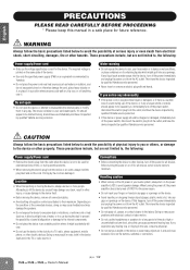
... Yamaha service personnel. • Never insert or remove an electric plug with electrical contact or fader motion. • Do not use the headphones or speakers for the device. Depending on , trip over, or roll anything over . • Do not use excessive force on or off the power for future reference. WARNING Always follow the basic precautions listed below to , the following : Power supply/Power cord...
... Yamaha service personnel. • Never insert or remove an electric plug with electrical contact or fader motion. • Do not use the headphones or speakers for the device. Depending on , trip over, or roll anything over . • Do not use excessive force on or off the power for future reference. WARNING Always follow the basic precautions listed below to , the following : Power supply/Power cord...
Owner's Manual
Page 5
... qualifi ed Yamaha service personnel about replacing defective components. European models Purchaser/User Information specified in use or modifications to MIDI data and/or audio data is governed by improper use . Do not attempt to change or modify products of specifications at the end of this manual before installing the application.) • Copying of the software or reproduction of...
... qualifi ed Yamaha service personnel about replacing defective components. European models Purchaser/User Information specified in use or modifications to MIDI data and/or audio data is governed by improper use . Do not attempt to change or modify products of specifications at the end of this manual before installing the application.) • Copying of the software or reproduction of...
Owner's Manual
Page 6
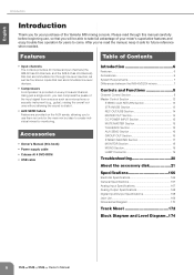
... Digital Input/Output Specifications 168 Jack List 169 Dimensional Diagram 170 Track Sheet 172 Block Diagram and Level Diagram..174 6 Owner's Manual English Introduction Introduction Thank you will be able to take full advantage of your purchase of the Yamaha IM8 mixing console. Features Table of Contents • Input channels The console provides 40 monaural input channels (the IM8-32 has 32 channels, and the IM8-24 has 24 channels) that can accommodate line-level devices. • Compressors A compressor is provided on the AUX sends...
... Digital Input/Output Specifications 168 Jack List 169 Dimensional Diagram 170 Track Sheet 172 Block Diagram and Level Diagram..174 6 Owner's Manual English Introduction Introduction Thank you will be able to take full advantage of your purchase of the Yamaha IM8 mixing console. Features Table of Contents • Input channels The console provides 40 monaural input channels (the IM8-32 has 32 channels, and the IM8-24 has 24 channels) that can accommodate line-level devices. • Compressors A compressor is provided on the AUX sends...
Owner's Manual
Page 8
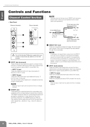
... of the external processor To the INSERT jack Tip: OUT 1 4 2 3 Turn off the Yamaha PW8 power supply before the channel fader (pre-fader) or the signal after the channel fader (post-fader) by changing an internal jumper. The INSERT jacks are impedance balanced (page 19) phone-jack type outputs. They output the signal that connect line-level instruments, such as illustrated below (insert cable sold separately). To the input jack of jack can connect either balanced or unbalanced phone plugs to connect microphones or musical instruments...
... of the external processor To the INSERT jack Tip: OUT 1 4 2 3 Turn off the Yamaha PW8 power supply before the channel fader (pre-fader) or the signal after the channel fader (post-fader) by changing an internal jumper. The INSERT jacks are impedance balanced (page 19) phone-jack type outputs. They output the signal that connect line-level instruments, such as illustrated below (insert cable sold separately). To the input jack of jack can connect either balanced or unbalanced phone plugs to connect microphones or musical instruments...

Owner's Manual
Page 9
...; Stereo channel -34dB to mix a phase-reversed signal, the signals will interfere with each other device with a low input level to phantom power. STEREO OUT master fader and GROUP OUT faders - If you omit this precaution, you 've connected a microphone or other , resulting in degraded sound quality. 9 (High Pass Filter) Switch This switch toggles the HPF on and off for a monaural channel. The adjustable sensitivity range is as these will invert the phase of the input signal. Owner's Manual 9 English Turn...
...; Stereo channel -34dB to mix a phase-reversed signal, the signals will interfere with each other device with a low input level to phantom power. STEREO OUT master fader and GROUP OUT faders - If you omit this precaution, you 've connected a microphone or other , resulting in degraded sound quality. 9 (High Pass Filter) Switch This switch toggles the HPF on and off for a monaural channel. The adjustable sensitivity range is as these will invert the phase of the input signal. Owner's Manual 9 English Turn...
Owner's Manual
Page 10
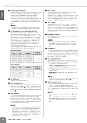
...; When a channel is muted, the ON indicator (G) will light red when the input signal reaches 3 dB before the channel fader via the MONITOR OUT jacks and the PHONES jack. 10 Owner's Manual Setting the gain control to the "▼" position produces a flat nominal level. If this case, the signal will not be charged for four frequency bands (HIGH, HI-MID, LO-MID, LOW). The signal adjusted by these switches select...
...; When a channel is muted, the ON indicator (G) will light red when the input signal reaches 3 dB before the channel fader via the MONITOR OUT jacks and the PHONES jack. 10 Owner's Manual Setting the gain control to the "▼" position produces a flat nominal level. If this case, the signal will not be charged for four frequency bands (HIGH, HI-MID, LO-MID, LOW). The signal adjusted by these switches select...
Owner's Manual
Page 11
.... Controls and Functions Owner's Manual 11 L Channel Fader Adjusts the output level of the input channel signal. NOTE · To minimize noise, the faders of unused channels should be set to the lowest position. · The channel faders will light. Use these faders to adjust the balance between the various channels. English K PFL Switch/Indicator When the PFL switch is on the PFL switch, the PFL indicator of the MONITOR section (page 18) will affect the ST, MONO, GROUP 1- 8, and AUX...
.... Controls and Functions Owner's Manual 11 L Channel Fader Adjusts the output level of the input channel signal. NOTE · To minimize noise, the faders of unused channels should be set to the lowest position. · The channel faders will light. Use these faders to adjust the balance between the various channels. English K PFL Switch/Indicator When the PFL switch is on the PFL switch, the PFL indicator of the MONITOR section (page 18) will affect the ST, MONO, GROUP 1- 8, and AUX...

Owner's Manual
Page 13
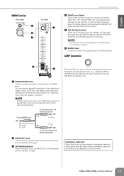
... jacks. English STEREO AUX RETURN Section Rear Panel Top Panel 1 2 3 Controls and Functions 5 PFL Switch/Indicator When the PFL switch is on the PFL switch, the PFL indicator in the MONITOR section (page 18) will light and the signal before the AUX controls and RETURN control in the STEREO AUX RETURN section is output to receive the signal returned from an external effect device (reverb, delay, etc.). NOTE · When you want to connect a CD player, and output the signal...
... jacks. English STEREO AUX RETURN Section Rear Panel Top Panel 1 2 3 Controls and Functions 5 PFL Switch/Indicator When the PFL switch is on the PFL switch, the PFL indicator in the MONITOR section (page 18) will light and the signal before the AUX controls and RETURN control in the STEREO AUX RETURN section is output to receive the signal returned from an external effect device (reverb, delay, etc.). NOTE · When you want to connect a CD player, and output the signal...
Owner's Manual
Page 14
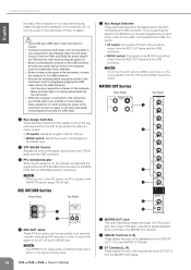
... switch, the PFL indicator of the MONO bus will light. 4 REC OUT/USB Section Rear Panel Top Panel 5 1 2 1 REC OUT Jacks These RCA pin jacks can be output. This jack outputs the signal adjusted by the controls in the following before turning the power to the instrument on/off then on again. • Use an AB type USB cable of less than about 3 meters. • To prevent loud pops and noises, turn on , the mixed signals...
... switch, the PFL indicator of the MONO bus will light. 4 REC OUT/USB Section Rear Panel Top Panel 5 1 2 1 REC OUT Jacks These RCA pin jacks can be output. This jack outputs the signal adjusted by the controls in the following before turning the power to the instrument on/off then on again. • Use an AB type USB cable of less than about 3 meters. • To prevent loud pops and noises, turn on , the mixed signals...
Owner's Manual
Page 15
Turning a switch (1-4) on will light when the Yamaha PW8 power supply is connected to the console and the PW8 is turned on . English Controls and Functions 4 MONO Control This control adjusts the level of the signal sent from MONO OUT to the MATRIX OUT jacks. 5 MATRIX master Control This control adjusts the overall level of the input channels will be enabled. 1 1 MUTE Master Switches/Indicators (1-4) These switches toggle input channel muting on , the indicator will flash and the talkback function will go dark. Reverse this...
Turning a switch (1-4) on will light when the Yamaha PW8 power supply is connected to the console and the PW8 is turned on . English Controls and Functions 4 MONO Control This control adjusts the level of the signal sent from MONO OUT to the MATRIX OUT jacks. 5 MATRIX master Control This control adjusts the overall level of the input channels will be enabled. 1 1 MUTE Master Switches/Indicators (1-4) These switches toggle input channel muting on , the indicator will flash and the talkback function will go dark. Reverse this...

Owner's Manual
Page 16
...; Patching external devices via an INSERT jack requires a special insert cable such as illustrated below (insert cable sold separately). To the input jack of the external processor 4 AUX SEND Fader Controls the level of the signal output to the MONITOR OUT and PHONES jacks for example, to connect to monitor the signal after the AUX SEND fader. Controls and Functions English AUX SEND Section Rear Panel Top Panel 1 2 3 4 5 1 AUX INSERT Jack This is an input/output jack located before the GROUP OUT fader. The "-20" LED will light if the output signal level reaches -20...
...; Patching external devices via an INSERT jack requires a special insert cable such as illustrated below (insert cable sold separately). To the input jack of the external processor 4 AUX SEND Fader Controls the level of the signal output to the MONITOR OUT and PHONES jacks for example, to connect to monitor the signal after the AUX SEND fader. Controls and Functions English AUX SEND Section Rear Panel Top Panel 1 2 3 4 5 1 AUX INSERT Jack This is an input/output jack located before the GROUP OUT fader. The "-20" LED will light if the output signal level reaches -20...

Owner's Manual
Page 17
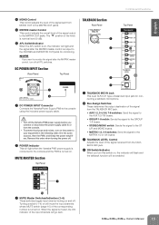
... switch is on , the indicator will light red when the GROUP OUT signal reaches 3 dB before the STEREO OUT master fader. STEREO MASTER Section Rear Panel 1 2 3 4 5 6 7 Controls and Functions Top Panel 1 STEREO INSERT Jack This is output to a multi-track recorder, external mixer, or other signal processor. You can connect these jacks to the MONITOR OUT and PHONES jacks for monitoring. English 2 GROUP OUT Jacks These are TRS phone type impedance-balanced (page 19) output jacks that carries both the send and return signal (tip = send...
... switch is on , the indicator will light red when the GROUP OUT signal reaches 3 dB before the STEREO OUT master fader. STEREO MASTER Section Rear Panel 1 2 3 4 5 6 7 Controls and Functions Top Panel 1 STEREO INSERT Jack This is output to a multi-track recorder, external mixer, or other signal processor. You can connect these jacks to the MONITOR OUT and PHONES jacks for monitoring. English 2 GROUP OUT Jacks These are TRS phone type impedance-balanced (page 19) output jacks that carries both the send and return signal (tip = send...
Owner's Manual
Page 18
... jacks for monitoring. 6 AFL Switch/Indicator When the AFL switch is being sent; English Controls and Functions NOTE · Patching external devices via an INSERT jack requires a special insert cable such as illustrated below (insert cable sold separately). They output the signal adjusted by the STEREO OUT master faders (7). These jacks output the signal before or after the STEREO OUT master faders, turn off all PFL switches. 2 PHONES Jack Connects a pair of the signal output to monitor the signal after the faders for monitoring. To the input jack...
... jacks for monitoring. 6 AFL Switch/Indicator When the AFL switch is being sent; English Controls and Functions NOTE · Patching external devices via an INSERT jack requires a special insert cable such as illustrated below (insert cable sold separately). They output the signal adjusted by the STEREO OUT master faders (7). These jacks output the signal before or after the STEREO OUT master faders, turn off all PFL switches. 2 PHONES Jack Connects a pair of the signal output to monitor the signal after the faders for monitoring. To the input jack...
Owner's Manual
Page 19
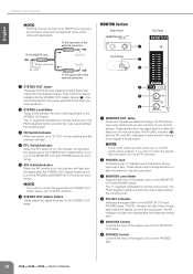
... indicator will light and the signal after the MONO fader. sleeve = ground). The IM8-40 mixer has three of impedance balanced output jacks have two. Owner's Manual 19 English MONO Section Rear Panel 1 2 3 Top Panel 4 Controls and Functions 4 MONO Level Meter Three LEDs indicate the signal level after the MONO fader is output to the MONITOR OUT and PHONES jacks for monitoring. NOTE · If you want to monitor the signal after the MONO fader, turn off all PFL switches. 6 MONO Fader Controls the level of the signal output to a separately...
... indicator will light and the signal after the MONO fader. sleeve = ground). The IM8-40 mixer has three of impedance balanced output jacks have two. Owner's Manual 19 English MONO Section Rear Panel 1 2 3 Top Panel 4 Controls and Functions 4 MONO Level Meter Three LEDs indicate the signal level after the MONO fader is output to the MONITOR OUT and PHONES jacks for monitoring. NOTE · If you want to monitor the signal after the MONO fader, turn off all PFL switches. 6 MONO Fader Controls the level of the signal output to a separately...
Owner's Manual
Page 20
...; Assign the MC's input channel to the MONO bus, and use the REC OUT section bus assign switch to send the output of the GROUP bus without sending it is off the IM8's COMP control. If you monitor the AFL signal of MATRIX 1-2 (or MATRIX 3-4) to an AUX bus by changing an internal jumper setting. In this case, the signal will be mixing a phase-reversed signal? The PW8 itself will let you are capturing the sound using the included power supply cable...
...; Assign the MC's input channel to the MONO bus, and use the REC OUT section bus assign switch to send the output of the GROUP bus without sending it is off the IM8's COMP control. If you monitor the AFL signal of MATRIX 1-2 (or MATRIX 3-4) to an AUX bus by changing an internal jumper setting. In this case, the signal will be mixing a phase-reversed signal? The PW8 itself will let you are capturing the sound using the included power supply cable...
Owner's Manual
Page 22
..., DO NOT INSTALL, COPY, OR OTHERWISE USE THIS SOFTWARE. The SOFTWARE and related documentation are entitled to claim ownership of the data created with a copy of the software program(s) and data ("SOFTWARE") accompanying this Agreement. YOU ARE ONLY PERMITTED TO USE THIS SOFTWARE PURSUANT TO THE TERMS AND CONDITIONS OF THIS AGREEMENT. In no event shall Yamaha's total liability to be free from Yamaha. Any dispute...
..., DO NOT INSTALL, COPY, OR OTHERWISE USE THIS SOFTWARE. The SOFTWARE and related documentation are entitled to claim ownership of the data created with a copy of the software program(s) and data ("SOFTWARE") accompanying this Agreement. YOU ARE ONLY PERMITTED TO USE THIS SOFTWARE PURSUANT TO THE TERMS AND CONDITIONS OF THIS AGREEMENT. In no event shall Yamaha's total liability to be free from Yamaha. Any dispute...
Owner's Manual
Page 25
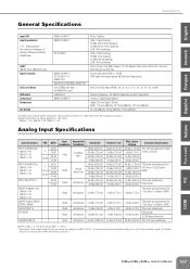
... INPUT A (MONO CHs) IM8-40: 1-40 IM8-32: 1-32 IM8-40: 1-24 INPUT B (MONO CHs) IM8-40: 1-40 IM8-32: 1-32 IM8-40: 1-24 INPUT A/B (ST CHs) INSERT IN (MONO CHs) IM8-40: 1-40 IM8-32: 1-32 IM8-40: 1-24 INSERT IN (AUX, GROUP, STEREO, MONO) AUX RETURN 1-4 2TR IN L/R TALKBACK MIC IN PAD 0 26 dB 0 26 dB - - - LAMP IM8-40: 3 pcs, IM8-32/24: 2pcs Signal Indicator LED Level Meter USB Audio Compressor Dimensions Net Weight MONO CH INPUT* MONO CH INPUT* ST CH INPUT MONO CH INPUT* ST CH INPUT 1-4 INSERT OUT GROUP OUT, AUX SEND, MONO OUT Post STEREO OUT fader Pre MONITOR control USB IN/OUT MONO CH INPUT...
... INPUT A (MONO CHs) IM8-40: 1-40 IM8-32: 1-32 IM8-40: 1-24 INPUT B (MONO CHs) IM8-40: 1-40 IM8-32: 1-32 IM8-40: 1-24 INPUT A/B (ST CHs) INSERT IN (MONO CHs) IM8-40: 1-40 IM8-32: 1-32 IM8-40: 1-24 INSERT IN (AUX, GROUP, STEREO, MONO) AUX RETURN 1-4 2TR IN L/R TALKBACK MIC IN PAD 0 26 dB 0 26 dB - - - LAMP IM8-40: 3 pcs, IM8-32/24: 2pcs Signal Indicator LED Level Meter USB Audio Compressor Dimensions Net Weight MONO CH INPUT* MONO CH INPUT* ST CH INPUT MONO CH INPUT* ST CH INPUT 1-4 INSERT OUT GROUP OUT, AUX SEND, MONO OUT Post STEREO OUT fader Pre MONITOR control USB IN/OUT MONO CH INPUT...
Owner's Manual
Page 32
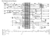
... DR PE A K +10 +6 +3 0 -3 -6 -10 -15 -20 -25 -30 L RECOUT [-10dBV] [-7.8dBu] R AUX SEND 1-8 [+4dBu] L MONITOR OUT [+4dBu] R PHONES [3mW 40ohms] CTRL MUTEMASTER 1 RED 2 RED 3 RED 4 RED POWER GR Clip Level(GROUP) BUS(GROUP, ST, MONO, PFL, AFL) GROUP INSERT I/O [0dBu] BUS(AUX) AUX INV GROUP Fader [Nominal:-10dB] GROUP OUT [+4dBu] ST, MONO, AUX INSERT I/O [0dBu] ST, MONO, AUX Fader [Nominal:-10dB] USB OUT(L) USB OUT(R) LPF [0dBu] LPF USB IN(L) USB IN(R) LPF [0dBu] LPF LIN...
... DR PE A K +10 +6 +3 0 -3 -6 -10 -15 -20 -25 -30 L RECOUT [-10dBV] [-7.8dBu] R AUX SEND 1-8 [+4dBu] L MONITOR OUT [+4dBu] R PHONES [3mW 40ohms] CTRL MUTEMASTER 1 RED 2 RED 3 RED 4 RED POWER GR Clip Level(GROUP) BUS(GROUP, ST, MONO, PFL, AFL) GROUP INSERT I/O [0dBu] BUS(AUX) AUX INV GROUP Fader [Nominal:-10dB] GROUP OUT [+4dBu] ST, MONO, AUX INSERT I/O [0dBu] ST, MONO, AUX Fader [Nominal:-10dB] USB OUT(L) USB OUT(R) LPF [0dBu] LPF USB IN(L) USB IN(R) LPF [0dBu] LPF LIN...


