

Owner's Manual
Page 1
..., Japan Powered Mixer Tables de mixage á amplification de puissance Aktiv-Mischpult Operation Manual Manuel d'instructions Bedienungsanleitung INPUT A CD IN -6dB B L L EFFECT RETURN +4dB 1L/ MONO 2L/ MONO EFFECT SEND +4dB 1 R R 1R 2R 2 A A REC OUT TAPE IN LINE INSERT I/O +4dB MONITOR OUT +4dB -10dBV -10dBV BALANCED L L L L A B B R R R R B CH I/O INSERT I/O 0dB INSERT 1 2 3 4 5 6 7 8 9 10 11 12 13 14 15 16 OUT IN PRE GEQ POST GEQ L ST R 1 A B PAD 20dB PEAK SIGNAL 2 A B PAD...
..., Japan Powered Mixer Tables de mixage á amplification de puissance Aktiv-Mischpult Operation Manual Manuel d'instructions Bedienungsanleitung INPUT A CD IN -6dB B L L EFFECT RETURN +4dB 1L/ MONO 2L/ MONO EFFECT SEND +4dB 1 R R 1R 2R 2 A A REC OUT TAPE IN LINE INSERT I/O +4dB MONITOR OUT +4dB -10dBV -10dBV BALANCED L L L L A B B R R R R B CH I/O INSERT I/O 0dB INSERT 1 2 3 4 5 6 7 8 9 10 11 12 13 14 15 16 OUT IN PRE GEQ POST GEQ L ST R 1 A B PAD 20dB PEAK SIGNAL 2 A B PAD...
Owner's Manual
Page 2
... the manual in 12- Your Yamaha EMX3500 Powered Mixer is an ideal choice for each of which is available in a safe place for convenient powering of external effects and monitoring systems, and a PAN control that allows overall output response shaping and feedback control in order to pan the channel signal across the master stereo bus. and 16-channel models, each channel, the EMX3500 offers both pre-GEQ and post-GEQ line insertion to the master stereo bus...
... the manual in 12- Your Yamaha EMX3500 Powered Mixer is an ideal choice for each of which is available in a safe place for convenient powering of external effects and monitoring systems, and a PAN control that allows overall output response shaping and feedback control in order to pan the channel signal across the master stereo bus. and 16-channel models, each channel, the EMX3500 offers both pre-GEQ and post-GEQ line insertion to the master stereo bus...

Owner's Manual
Page 3
... which is being affected by YAMAHA KEMBLE MUSIC (U.K.) LTD. This equipment generates/uses radio frequencies and, if not installed and used . Cable/s supplied with the coloured markings identifying the terminals in FCC Regulations, Part 15 for Class "B" digital devices. IMPORTANT NOTICE: DO NOT MODIFY THIS UNIT! If you can be used according to the instructions found to use of fuse) circuits or install AC line filter/s.
... which is being affected by YAMAHA KEMBLE MUSIC (U.K.) LTD. This equipment generates/uses radio frequencies and, if not installed and used . Cable/s supplied with the coloured markings identifying the terminals in FCC Regulations, Part 15 for Class "B" digital devices. IMPORTANT NOTICE: DO NOT MODIFY THIS UNIT! If you can be used according to the instructions found to use of fuse) circuits or install AC line filter/s.

Owner's Manual
Page 4
CONTENTS PRECAUTIONS ...3 CONTROLS AND CONNECTORS 4 Front Panel: Input Channel Controls 4 Front Panel: Master Control Section 6 Top Panel ...8 Rear Panel ...10 OPERATING TIPS ...11 Cautions for Connected Sources 11 Matching Input Levels 11 Setting Channel and Master Faders 11 Using the Channel Equalizers 12 Using the Digital Signal Processor 12 Using the Graphic Equalizer 13 Connecting Speakers 13 CONNECTION EXAMPLE 14 SPECIFICATIONS ...15 Input Characteristics 16 Output Characteristics 16 Console Dimensions 17 BLOCK AND LEVEL DIAGRAMS 18 2
CONTENTS PRECAUTIONS ...3 CONTROLS AND CONNECTORS 4 Front Panel: Input Channel Controls 4 Front Panel: Master Control Section 6 Top Panel ...8 Rear Panel ...10 OPERATING TIPS ...11 Cautions for Connected Sources 11 Matching Input Levels 11 Setting Channel and Master Faders 11 Using the Channel Equalizers 12 Using the Digital Signal Processor 12 Using the Graphic Equalizer 13 Connecting Speakers 13 CONNECTION EXAMPLE 14 SPECIFICATIONS ...15 Input Characteristics 16 Output Characteristics 16 Console Dimensions 17 BLOCK AND LEVEL DIAGRAMS 18 2
Owner's Manual
Page 5
... user-serviceable parts. Refer all maintenance and repairs to high temperatures or humidity. Handle the mixer with the power on the rear panel of your local AC mains supply. • KEEP SPEAKER PLUGS CLEAN Solid phone plugs can damage the it is likely to be exposed to qualified Yamaha service personnel. Also avoid locations where the mixer may be sure to read the precautions in the rear-panel SPEAKER jacks...
... user-serviceable parts. Refer all maintenance and repairs to high temperatures or humidity. Handle the mixer with the power on the rear panel of your local AC mains supply. • KEEP SPEAKER PLUGS CLEAN Solid phone plugs can damage the it is likely to be exposed to qualified Yamaha service personnel. Also avoid locations where the mixer may be sure to read the precautions in the rear-panel SPEAKER jacks...

Owner's Manual
Page 6
... SIGNAL indicator lights when a signal of 10 dB below the channel's clipping point. If this does not work, reduce the output level of the connected source. 4 GAIN control This control adjusts the channel's input sensitivity between -40 dB and +4 dB when the PAD switch is off at the corresponding A input connector or B input jack on high-level transients, you check the level of the post-EQ/pre-fader signal. This feature can be filtered...
... SIGNAL indicator lights when a signal of 10 dB below the channel's clipping point. If this does not work, reduce the output level of the connected source. 4 GAIN control This control adjusts the channel's input sensitivity between -40 dB and +4 dB when the PAD switch is off at the corresponding A input connector or B input jack on high-level transients, you check the level of the post-EQ/pre-fader signal. This feature can be filtered...

Owner's Manual
Page 7
... MONITOR OUT jacks on the top panel after their final output levels have their overall level set by an external effect device. 9 EFFECT 2 control This control determines the level of the post-EQ/postfader signal that channel in the stereo sound field. The channel signals mixed by this bus have been set by the MONITOR A and B controls in the master control section. 8 EFFECT 1 control This control determines the level of the post-EQ/postfader signal that channel will be processed by the EFFECT SEND 1 fader...
... MONITOR OUT jacks on the top panel after their final output levels have their overall level set by an external effect device. 9 EFFECT 2 control This control determines the level of the post-EQ/postfader signal that channel in the stereo sound field. The channel signals mixed by this bus have been set by the MONITOR A and B controls in the master control section. 8 EFFECT 1 control This control determines the level of the post-EQ/postfader signal that channel will be processed by the EFFECT SEND 1 fader...
Owner's Manual
Page 8
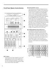
... nine linear controls, corresponding to "Using the Digital Signal Processor" on page 12 for the currently selected DSP program, which is changed using the master stereo faders. The EQ switch turns the graphic equalizer on the use of this section. These meters serve as useful guides when setting optimum output levels using the PROGRAM control. The PEAK LED lights when the DSP output signal nears the clipping level. Finally, the RESET switch can be used to its factory value. Refer...
... nine linear controls, corresponding to "Using the Digital Signal Processor" on page 12 for the currently selected DSP program, which is changed using the master stereo faders. The EQ switch turns the graphic equalizer on the use of this section. These meters serve as useful guides when setting optimum output levels using the PROGRAM control. The PEAK LED lights when the DSP output signal nears the clipping level. Finally, the RESET switch can be used to its factory value. Refer...

Owner's Manual
Page 9
... output signal is adjusted by phantom-powered condenser microphones. Signal sources that are set up using the MONITOR control of the unequalized pre-fader master mix signal that appears at the corresponding EFFECT RETURN jacks on the top panel (or from the internal digital signal processor, when the DSP is used . The EFFECT SEND 1 fader sets the overall level of the signal that is sent for use by both the master stereo faders and the PHONES control. however, the output level of each input channel. The CD IN A/B switch...
... output signal is adjusted by phantom-powered condenser microphones. Signal sources that are set up using the MONITOR control of the unequalized pre-fader master mix signal that appears at the corresponding EFFECT RETURN jacks on the top panel (or from the internal digital signal processor, when the DSP is used . The EFFECT SEND 1 fader sets the overall level of the signal that is sent for use by both the master stereo faders and the PHONES control. however, the output level of each input channel. The CD IN A/B switch...

Owner's Manual
Page 10
... 1 2 MONITOR OUT +4dB A R R R R B PRE GEQ POST GEQ T U V O Channel input connectors Each of the EMX3500's input channels is turned on the front panel is ideal for the connection of external signal processing devices or other effect that needs to be connected to the phone jack (B) when the PHANTOM POWER ON/ OFF switch is provided with both the send (output) and receive (input) lines required by the insert point. Q R S A CD IN -6dB B L L EFFECT RETURN +4dB 1L/ MONO...
... 1 2 MONITOR OUT +4dB A R R R R B PRE GEQ POST GEQ T U V O Channel input connectors Each of the EMX3500's input channels is turned on the front panel is ideal for the connection of external signal processing devices or other effect that needs to be connected to the phone jack (B) when the PHANTOM POWER ON/ OFF switch is provided with both the send (output) and receive (input) lines required by the insert point. Q R S A CD IN -6dB B L L EFFECT RETURN +4dB 1L/ MONO...

Owner's Manual
Page 11
... line insertion points are two pairs of jacks, allowing the devices to be returned to the master stereo mixing bus. V MONITOR OUT jacks These 1/4" phone jacks deliver the signal from a connected tape deck. Although both channels of the master stereo mixing bus, use the EFFECT RETURN L jack. (The R jack should be adjusted individually using the CD IN A/B switch on the front panel. Note that need to be applied to both these jacks output the same monitor mix signal, their output levels can...
... line insertion points are two pairs of jacks, allowing the devices to be returned to the master stereo mixing bus. V MONITOR OUT jacks These 1/4" phone jacks deliver the signal from a connected tape deck. Although both channels of the master stereo mixing bus, use the EFFECT RETURN L jack. (The R jack should be adjusted individually using the CD IN A/B switch on the front panel. Note that need to be applied to both these jacks output the same monitor mix signal, their output levels can...

Owner's Manual
Page 12
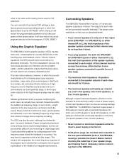
... speaker system must be as low as 4Ω. The VU meters on the front panel will light when the power is on and off. The EMX3500 provides two pairs of the speaker system may be no less than 8Ω. 10 If you connect a speaker system to only one of the jacks (SPEAKER 1 or SPEAKER 2), the total load impedance of stereo speaker output jacks, labeled SPEAKER 1 and SPEAKER 2. Rear Panel W POWER X SPEAKER 1 R L SPEAKER 2 R L W POWER switch This switch turns the EMX3500's power supply...
... speaker system must be as low as 4Ω. The VU meters on the front panel will light when the power is on and off. The EMX3500 provides two pairs of the speaker system may be no less than 8Ω. 10 If you connect a speaker system to only one of the jacks (SPEAKER 1 or SPEAKER 2), the total load impedance of stereo speaker output jacks, labeled SPEAKER 1 and SPEAKER 2. Rear Panel W POWER X SPEAKER 1 R L SPEAKER 2 R L W POWER switch This switch turns the EMX3500's power supply...
Owner's Manual
Page 13
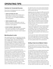
... mixer's POWER switch on after first turning on connected sound sources such as electronic instruments or audio equipment. • DO NOT CONNECT AMPLIFIED INPUT Never connect the speaker-level output of any cables. Gradually increase the setting of the mixer. This time the PEAK indicator should keep in the GAIN control range. Now apply a signal to check the connecting cable for faults. Matching Input Levels When matching input levels, it is properly connected to do so can be monitored using...
... mixer's POWER switch on after first turning on connected sound sources such as electronic instruments or audio equipment. • DO NOT CONNECT AMPLIFIED INPUT Never connect the speaker-level output of any cables. Gradually increase the setting of the mixer. This time the PEAK indicator should keep in the GAIN control range. Now apply a signal to check the connecting cable for faults. Matching Input Levels When matching input levels, it is properly connected to do so can be monitored using...
Owner's Manual
Page 14
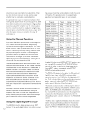
... master stereo faders when making small adjustments to equalization. Channel equalization can be most useful in the DIGITAL EFFECT section to turn the PROGRAM control. Slightly boosting the high frequency of boost being applied. The table below the clipping level. The EFFECT RETURN 2 controls will adjust the level of the signal output by the bank of LED indicators at the top of the DIGITAL EFFECT section. (When the POWER switch of the EMX3500...
... master stereo faders when making small adjustments to equalization. Channel equalization can be most useful in the DIGITAL EFFECT section to turn the PROGRAM control. Slightly boosting the high frequency of boost being applied. The table below the clipping level. The EFFECT RETURN 2 controls will adjust the level of the signal output by the bank of LED indicators at the top of the DIGITAL EFFECT section. (When the POWER switch of the EMX3500...
Owner's Manual
Page 15
... parameters of all of the EMX3500, causing a potential fire hazard. There are connected in the rear-panel SPEAKER jacks of the internal DSP settings to their preset values. Amplified sound produced in such environments can overheat when inserted in parallel internally. To get around this problem, try cutting response in the listening area, and feedback control. The outputs for each channel are many instances, however, in...
... parameters of all of the EMX3500, causing a potential fire hazard. There are connected in the rear-panel SPEAKER jacks of the internal DSP settings to their preset values. Amplified sound produced in such environments can overheat when inserted in parallel internally. To get around this problem, try cutting response in the listening area, and feedback control. The outputs for each channel are many instances, however, in...
Owner's Manual
Page 16
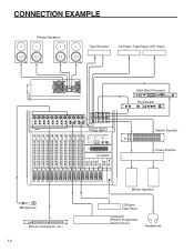
CONNECTION EXAMPLE PA-type Speakers Tape Recorder CD Player, Tape Player, DAT Player R L SPEAKER 2 SPEAKER 1 L R INPUT A CD IN -6dB B L L EFFECT RETURN +4dB 1L/ MONO 2L/ MONO EFFECT SEND +4dB 1 R R 1R 2R 2 A A REC OUT TAPE IN LINE INSERT I/O +4dB MONITOR OUT +4dB -10dBV -10dBV BALANCED L L L L A B B R R R R B CH I/O INSERT I/O 0dB INSERT 1 2 3 4 5 6 7 8 9 10 11 12 OUT IN PRE GEQ POST GEQ L ST R 1 A B PAD 20dB PEAK SIGNAL 2 A B PAD 20dB PEAK SIGNAL 3 A B PAD 20dB PEAK SIGNAL 4 A B PAD 20dB PEAK SIGNAL 5 A B PAD...
CONNECTION EXAMPLE PA-type Speakers Tape Recorder CD Player, Tape Player, DAT Player R L SPEAKER 2 SPEAKER 1 L R INPUT A CD IN -6dB B L L EFFECT RETURN +4dB 1L/ MONO 2L/ MONO EFFECT SEND +4dB 1 R R 1R 2R 2 A A REC OUT TAPE IN LINE INSERT I/O +4dB MONITOR OUT +4dB -10dBV -10dBV BALANCED L L L L A B B R R R R B CH I/O INSERT I/O 0dB INSERT 1 2 3 4 5 6 7 8 9 10 11 12 OUT IN PRE GEQ POST GEQ L ST R 1 A B PAD 20dB PEAK SIGNAL 2 A B PAD 20dB PEAK SIGNAL 3 A B PAD 20dB PEAK SIGNAL 4 A B PAD 20dB PEAK SIGNAL 5 A B PAD...

Owner's Manual
Page 17
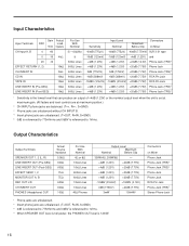
... Equivalent Input Noise -96dB Residual Output Noise (Pre-GEQ Out) -96dB Residual Output Noise (Effect Send, Monitor Out) -73dB Residual Output Noise (Speaker Out) -90dB (Pre-GEQ) Master fader at maximum level and all channel switches OFF. -80dB (EFFECT SEND) Master fader at maximum level and all channel EFFECT controls at minimum level. -83dB (MONITOR OUT) Master VR at maximum level and all channel MONITOR controls at 1kHz) 70dB Adjacent input channels 70dB Input to Output Input Channel Gain Control 44dB variable from -60dB to -16dB Input Channel PAD Switch 0/20dB of attenuation Input Channel...
... Equivalent Input Noise -96dB Residual Output Noise (Pre-GEQ Out) -96dB Residual Output Noise (Effect Send, Monitor Out) -73dB Residual Output Noise (Speaker Out) -90dB (Pre-GEQ) Master fader at maximum level and all channel switches OFF. -80dB (EFFECT SEND) Master fader at maximum level and all channel EFFECT controls at minimum level. -83dB (MONITOR OUT) Master VR at maximum level and all channel MONITOR controls at 1kHz) 70dB Adjacent input channels 70dB Input to Output Input Channel Gain Control 44dB variable from -60dB to -16dB Input Channel PAD Switch 0/20dB of attenuation Input Channel...
Owner's Manual
Page 18
... the nominal output level when the unit is set at maximum gain. (All faders and level controls are at maximum position.) 2 CH INPUT phone jacks are balanced. (T=+, R=-, S=GND) 3 Phone jacks are unbalanced without CH INPUT B. 4 Insert phone jacks are unbalanced. (T=OUT, R=IN, S=GND) 5 0dB is referenced to 775mVrms and 0dBV is referenced to 1Vrms. Output Characteristics Output Terminals SPEAKER OUT 1, 2 (L, R) LINE INSERT OUT (Pre-GEQ) LINE INSERT OUT (Post-GEQ) EFFECT SEND 1, 2 MONITOR OUT...
... the nominal output level when the unit is set at maximum gain. (All faders and level controls are at maximum position.) 2 CH INPUT phone jacks are balanced. (T=+, R=-, S=GND) 3 Phone jacks are unbalanced without CH INPUT B. 4 Insert phone jacks are unbalanced. (T=OUT, R=IN, S=GND) 5 0dB is referenced to 775mVrms and 0dBV is referenced to 1Vrms. Output Characteristics Output Terminals SPEAKER OUT 1, 2 (L, R) LINE INSERT OUT (Pre-GEQ) LINE INSERT OUT (Post-GEQ) EFFECT SEND 1, 2 MONITOR OUT...

Owner's Manual
Page 20
... POST GEQ R SUM INV PA ST R 9 BAND STEREO GEQ SPEAKER 1 L SPEAKER 2 L SPEAKER 1 R SPEAKER 2 R LEVEL MONITOR LEVEL MONITOR SUM SUM SUM REC OUT PAD PAD BA MONITOR A BA MONITOR B BA EFFECT SEND 1 BA EFFECT SEND 2 (EFFECT RETURN 2) DIGITAL EFFECT L REC OUT -10dBV R A MONITOR OUT +4dB B 1 EFFECT SEND +4dB 2 MONITOR L,R EFFECT 1,2 MONITOR OUT EFFECT SEND LINE INSERT I/O POST GEQ REC OUT PHONES [Phones] Pre-Emphasis LPF AD Keys CPU DSP Display DA De-Emphasis LPF DIGITAL EFFECT LINE INSERT I/O POST GEQ SPEAKER OUT +40 +30 +20 +10 0 Phones...
... POST GEQ R SUM INV PA ST R 9 BAND STEREO GEQ SPEAKER 1 L SPEAKER 2 L SPEAKER 1 R SPEAKER 2 R LEVEL MONITOR LEVEL MONITOR SUM SUM SUM REC OUT PAD PAD BA MONITOR A BA MONITOR B BA EFFECT SEND 1 BA EFFECT SEND 2 (EFFECT RETURN 2) DIGITAL EFFECT L REC OUT -10dBV R A MONITOR OUT +4dB B 1 EFFECT SEND +4dB 2 MONITOR L,R EFFECT 1,2 MONITOR OUT EFFECT SEND LINE INSERT I/O POST GEQ REC OUT PHONES [Phones] Pre-Emphasis LPF AD Keys CPU DSP Display DA De-Emphasis LPF DIGITAL EFFECT LINE INSERT I/O POST GEQ SPEAKER OUT +40 +30 +20 +10 0 Phones...


