
Owner's Manual
Page 2
... with the requirements listed in FCC Regulations, Part 15 for Class "B" digital devices. This equipment generates/uses radio frequencies and, if not installed and used . The wire which is coloured BLUE must be connected to the terminal which is marked with this manual, meets FCC requirements. Modifications not expressly approved by Yamaha may void your use the product. 2. Cable/s supplied with the...
... with the requirements listed in FCC Regulations, Part 15 for Class "B" digital devices. This equipment generates/uses radio frequencies and, if not installed and used . The wire which is coloured BLUE must be connected to the terminal which is marked with this manual, meets FCC requirements. Modifications not expressly approved by Yamaha may void your use the product. 2. Cable/s supplied with the...
Owner's Manual
Page 3
... all musical instruments, audio equipment, and speakers when connecting to do not touch the power cable plug if it to the SPEAKERS jack of lightning, do so is exposed), ask your dealer for a replacement. You could receive an electrical shock. If you think internal inspection, maintenance, or repair is necessary, contact your hearing. • Clean the contacts of the EMX3000 and enjoy long, trouble-free...
... all musical instruments, audio equipment, and speakers when connecting to do not touch the power cable plug if it to the SPEAKERS jack of lightning, do so is exposed), ask your dealer for a replacement. You could receive an electrical shock. If you think internal inspection, maintenance, or repair is necessary, contact your hearing. • Clean the contacts of the EMX3000 and enjoy long, trouble-free...
Owner's Manual
Page 4
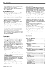
..., compared to Yamaha's previous models), and has lead to a reduction in . Contents Front and rear panel 1 Control panel 1 Input/output panel 6 Rear panel 8 Installation/Connections 9 Installation 9 Connection 9 Connecting input/output equipment 10 Basic operation 11 Connecting microphones and instruments .....11 Using the digital effect 11 Example setups 12 As a conference/entertainment hall sound system 12 As a band PA 13 Using a subwoofer 15 Specifications 16 General specifications 16 Input specifications 17 Output specifications 17 Dimensions 18 Block/Level Diagram 19
..., compared to Yamaha's previous models), and has lead to a reduction in . Contents Front and rear panel 1 Control panel 1 Input/output panel 6 Rear panel 8 Installation/Connections 9 Installation 9 Connection 9 Connecting input/output equipment 10 Basic operation 11 Connecting microphones and instruments .....11 Using the digital effect 11 Example setups 12 As a conference/entertainment hall sound system 12 As a band PA 13 Using a subwoofer 15 Specifications 16 General specifications 16 Input specifications 17 Output specifications 17 Dimensions 18 Block/Level Diagram 19
Owner's Manual
Page 5
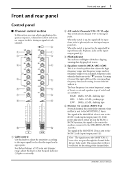
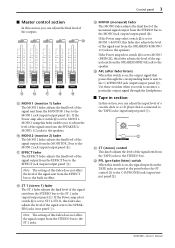
... range, and low frequency range of each channel. When the switch is sent to the MONITOR 1/2 buses does not pass through the channel fader 0 (pre-fader send). If the power amp select switch V is in the MONI 1MONO position, the signal is sent to the SPEAKERS L/MONI1 1/2 jacks. The signal of the MONITOR 2 bus is also sent to the speakers connected to the MONI 2 jack (input/output panel 9). EMX3000-Owner's Manual Front and rear panel 1 Front and rear panel Control panel s Channel control section In...
... range, and low frequency range of each channel. When the switch is sent to the MONITOR 1/2 buses does not pass through the channel fader 0 (pre-fader send). If the power amp select switch V is in the MONI 1MONO position, the signal is sent to the SPEAKERS L/MONI1 1/2 jacks. The signal of the MONITOR 2 bus is also sent to the speakers connected to the MONI 2 jack (input/output panel 9). EMX3000-Owner's Manual Front and rear panel 1 Front and rear panel Control panel s Channel control section In...

Owner's Manual
Page 6
... EFFECT jack (input/output panel A). The switch operation does not affect the signal sent to the STEREO bus, MONITOR 1/2 buses, or the EFFECT bus. 0 Channel fader This controls the output level of stereo signal sent from the ST SUB 1 and 2 jacks to the STEREO bus. B MONI 2 (monitor 2) control The MONI 2 knob adjusts the amount of the signal sent to the MONITOR 1/2 buses (pre-fader send). EMX3000-Owner's Manual Use this section, you wish to use the headphones to monitor only a specific channel. s Stereo sub input section In this when you can monitor the signal...
... EFFECT jack (input/output panel A). The switch operation does not affect the signal sent to the STEREO bus, MONITOR 1/2 buses, or the EFFECT bus. 0 Channel fader This controls the output level of stereo signal sent from the ST SUB 1 and 2 jacks to the STEREO bus. B MONI 2 (monitor 2) control The MONI 2 knob adjusts the amount of the signal sent to the MONITOR 1/2 buses (pre-fader send). EMX3000-Owner's Manual Use this section, you wish to use the headphones to monitor only a specific channel. s Stereo sub input section In this when you can monitor the signal...
Owner's Manual
Page 7
... ST control K to the C-R/PHONES jack (input/output panel B). I E MONI 1 (monitor 1) fader The MONI 1 fader adjusts the final level of the outputs. L PFL (pre-fader listen) switch When this fader does not affect the signal output from the TAPE jacks is connected to the TAPE jacks (input/output panel 5). EMX3000-Owner's Manual If the Power amp select switch V is set to MONI 1-MONO, this section, you can adjust the final level of the signal sent from the MONITOR 1 bus to the SPEAKERS jacks (rear panel 1). s Tape in effect. F MONI 2 (monitor 2) fader...
... ST control K to the C-R/PHONES jack (input/output panel B). I E MONI 1 (monitor 1) fader The MONI 1 fader adjusts the final level of the outputs. L PFL (pre-fader listen) switch When this fader does not affect the signal output from the TAPE jacks is connected to the TAPE jacks (input/output panel 5). EMX3000-Owner's Manual If the Power amp select switch V is set to MONI 1-MONO, this section, you can adjust the final level of the signal sent from the MONITOR 1 bus to the SPEAKERS jacks (rear panel 1). s Tape in effect. F MONI 2 (monitor 2) fader...
Owner's Manual
Page 8
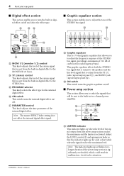
... of the internal digital effect. s Power amp section This section allows you to select the signals that is output from the ST 1/2 jacks (input/output panel 8), and MONO jack (input/output panel 0). Adjust the LEVEL control U and appropriate fader so that allows you to adjust the frequency response of the STEREO bus signal, providing a maximum of ±12 dB of the return signal that will be sent to the STEREO bus. Note: The indicator lights up or flashes for...
... of the internal digital effect. s Power amp section This section allows you to select the signals that is output from the ST 1/2 jacks (input/output panel 8), and MONO jack (input/output panel 0). Adjust the LEVEL control U and appropriate fader so that allows you to adjust the frequency response of the STEREO bus signal, providing a maximum of ±12 dB of the return signal that will be sent to the STEREO bus. Note: The indicator lights up or flashes for...
Owner's Manual
Page 9
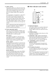
...for the MIC input jacks for channels 1~8. The final level of these signals is adjusted by the master MONI 1 fader and the MONO fader. • MONO (BRIDGE) The monaural signal that is a mix of the STEREO bus signals is adjusted by the master MONO fader. Y PHANTOM (+48V) switch and indicator This switch turns the phantom power supply on the rear panel. • ST1 L-ST1 R The STEREO bus signals are output from the SPEAKERS L/MONI1 1/2 jacks and the SPEAKERS R/MONO 1/2 jacks. EMX3000-Owner's Manual V Power amp select switch Select one speaker to play a loud sound. Note: The...
...for the MIC input jacks for channels 1~8. The final level of these signals is adjusted by the master MONI 1 fader and the MONO fader. • MONO (BRIDGE) The monaural signal that is a mix of the STEREO bus signals is adjusted by the master MONO fader. Y PHANTOM (+48V) switch and indicator This switch turns the phantom power supply on the rear panel. • ST1 L-ST1 R The STEREO bus signals are output from the SPEAKERS L/MONI1 1/2 jacks and the SPEAKERS R/MONO 1/2 jacks. EMX3000-Owner's Manual V Power amp select switch Select one speaker to play a loud sound. Note: The...

Owner's Manual
Page 10
... condenser microphones must be connected to insert an external effect processor, such as shown in the following diagram. By using the GAIN control (control panel 1) you can provide +48V phantom power, allowing you to the LINE input jacks of the external processor EMX3000-Owner's Manual Both MIC and LINE are the input jacks for the MIC and LINE jacks are TRS phone jacks that enable you to the output jack of channels 1~8 or channel 9/10~11/12 input jacks if the PHANTOM +48V switch (control panel Y) is switched on . 2 INSERT I/O (insert) jacks...
... condenser microphones must be connected to insert an external effect processor, such as shown in the following diagram. By using the GAIN control (control panel 1) you can provide +48V phantom power, allowing you to the LINE input jacks of the external processor EMX3000-Owner's Manual Both MIC and LINE are the input jacks for the MIC and LINE jacks are TRS phone jacks that enable you to the output jack of channels 1~8 or channel 9/10~11/12 input jacks if the PHANTOM +48V switch (control panel Y) is switched on . 2 INSERT I/O (insert) jacks...
Owner's Manual
Page 11
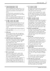
Use the A/B switch (control panel 2) to record the signal from the STEREO bus. Use the LEVEL control (control panel U) to adjust the level of the signal input to the power amplifier. 7 REC (record) jacks These phono jacks are used to connect to the inputs of the signal output from an external device, such as a delay or echo can be routed to switch the built-in digital effect on/off. C FOOT SW (foot switch) jack A separately sold Yamaha FC5 foot switch can be connected to this jack so you insert a plug into this...
Use the A/B switch (control panel 2) to record the signal from the STEREO bus. Use the LEVEL control (control panel U) to adjust the level of the signal input to the power amplifier. 7 REC (record) jacks These phono jacks are used to connect to the inputs of the signal output from an external device, such as a delay or echo can be routed to switch the built-in digital effect on/off. C FOOT SW (foot switch) jack A separately sold Yamaha FC5 foot switch can be connected to this jack so you insert a plug into this...
Owner's Manual
Page 12
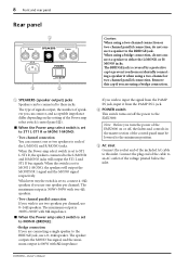
.... When the switch is set to this cap if you are using a bridge connection, do not connect a speaker to the BRIDGE jack, use one or two speakers to each of the EMX3000 on /off , the faders and controls in the master section of the control panel must be connected to an AC outlet of the Power amp select switch (control panel V). 8 Front and rear panel Rear panel 1 R/MONO 2 1 SPEAKERS L/MONI 1 2 1 AC IN BRIDGE POWER ON OFF 3 2 1 SPEAKERS (speaker output) jacks Speakers can be...
.... When the switch is set to this cap if you are using a bridge connection, do not connect a speaker to the BRIDGE jack, use one or two speakers to each of the EMX3000 on /off , the faders and controls in the master section of the control panel must be connected to an AC outlet of the Power amp select switch (control panel V). 8 Front and rear panel Rear panel 1 R/MONO 2 1 SPEAKERS L/MONI 1 2 1 AC IN BRIDGE POWER ON OFF 3 2 1 SPEAKERS (speaker output) jacks Speakers can be...

Owner's Manual
Page 13
... both jack 1 and jack 2 of SPEAKERS R/MONO. 2 Two-channel parallel connection - Refer to the EMX3000. 1 Two-channel connection - When connecting the speaker jacks to speakers, you must use cables and plugs of these, the required speaker impedance will differ. A single speaker each of the appropriate standard. For each can be connected to the BRIDGE jack. Installation/Connections 9 Installation/Connections Installation The EMX3000 uses a forced cooling system with air intake on the right side and exhaust on the rear.
... both jack 1 and jack 2 of SPEAKERS R/MONO. 2 Two-channel parallel connection - Refer to the EMX3000. 1 Two-channel connection - When connecting the speaker jacks to speakers, you must use cables and plugs of these, the required speaker impedance will differ. A single speaker each of the appropriate standard. For each can be connected to the BRIDGE jack. Installation/Connections 9 Installation/Connections Installation The EMX3000 uses a forced cooling system with air intake on the right side and exhaust on the rear.

Owner's Manual
Page 14
... INSERT I O 5 OUT IN 6 MIC LINE 7 MIC 9 L B LINE 10 R B 9 L (MONO) A 10 R A 8 9 10 11 L (MONO) A 12 R A 11 12 11 L B 12 R B L TAPE -10dBV R L (MONO) R ST SUB 1 +4dB OUTPUT L L REC -10dBV L R L (MONO) MONI 1 R ST SUB 2 +4dB L BRIDGE R ST 1 +4dB R ST 2 +4dB MONI 2 +4dB R P.AMP IN +4dB FOOT SW MONO +4dB EFFECT +4dB C-R PHONES Power amplifier Synthesizer 88 Effect processor (compressor) Drum machine Headphones 88 Effect processor (reverb) Monitor speakers Additional/alternative PA system Normally, connect speakers to the jacks on the rear panel. EMX3000-Owner's Manual...
... INSERT I O 5 OUT IN 6 MIC LINE 7 MIC 9 L B LINE 10 R B 9 L (MONO) A 10 R A 8 9 10 11 L (MONO) A 12 R A 11 12 11 L B 12 R B L TAPE -10dBV R L (MONO) R ST SUB 1 +4dB OUTPUT L L REC -10dBV L R L (MONO) MONI 1 R ST SUB 2 +4dB L BRIDGE R ST 1 +4dB R ST 2 +4dB MONI 2 +4dB R P.AMP IN +4dB FOOT SW MONO +4dB EFFECT +4dB C-R PHONES Power amplifier Synthesizer 88 Effect processor (compressor) Drum machine Headphones 88 Effect processor (reverb) Monitor speakers Additional/alternative PA system Normally, connect speakers to the jacks on the rear panel. EMX3000-Owner's Manual...
Owner's Manual
Page 15
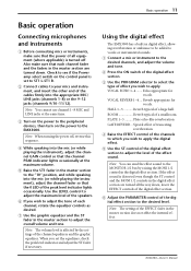
... instrument, and insert the other end of the digital effect section to apply. EMX3000-Owner's Manual Basic operation 11 Basic operation Connecting microphones and instruments 1 Before connecting mics or instruments, make sure that each channel, rotate the equalizer controls as desired. 7 Use the graphic equalizer and the ST fader in the master section to the MONITOR 1/2 bus by the settings of each channel fader and the faders in the master section are turned all the...
... instrument, and insert the other end of the digital effect section to apply. EMX3000-Owner's Manual Basic operation 11 Basic operation Connecting microphones and instruments 1 Before connecting mics or instruments, make sure that each channel, rotate the equalizer controls as desired. 7 Use the graphic equalizer and the ST fader in the master section to the MONITOR 1/2 bus by the settings of each channel fader and the faders in the master section are turned all the...
Owner's Manual
Page 16
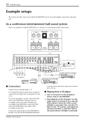
... also be used, and explains connections and operation. Use the GAIN control of the peak indicator will light occasionally. Then, raise the ST 1 fader to the output of using the EMX3000 as a conference or entertainment hall sound system. EMX3000-Owner's Manual R/MONO 2 1 SPEAKERS L/MONI 1 2 1 BRIDGE R 2 R 1 L 2 L 1 Main speakers MIC LINE INSERT I O 1 MIC LINE INSERT I O 2 MIC LINE INSERT I O 3 INPUT MIC MIC MIC LINE INSERT I O 4 LINE LINE 0dB INSERT I O 5 OUT IN 6 MIC LINE 7 MIC 9 L B LINE 10 R B 9 L (MONO) A 10 R A 8 9 10 11 L (MONO) A 12...
... also be used, and explains connections and operation. Use the GAIN control of the peak indicator will light occasionally. Then, raise the ST 1 fader to the output of using the EMX3000 as a conference or entertainment hall sound system. EMX3000-Owner's Manual R/MONO 2 1 SPEAKERS L/MONI 1 2 1 BRIDGE R 2 R 1 L 2 L 1 Main speakers MIC LINE INSERT I O 1 MIC LINE INSERT I O 2 MIC LINE INSERT I O 3 INPUT MIC MIC MIC LINE INSERT I O 4 LINE LINE 0dB INSERT I O 5 OUT IN 6 MIC LINE 7 MIC 9 L B LINE 10 R B 9 L (MONO) A 10 R A 8 9 10 11 L (MONO) A 12...

Owner's Manual
Page 17
... using an external effect, we recommend that you turn down all the way down for a band. Set the Power amp select switch to "MONI 1MONO." • If you use an external effect such as keyboards, to channel input jacks 1~12. • Connect the main speakers to the SPEAKERS R/ MONO 1/2 jacks, and connect the monitor speakers to the EMX3000's ST SUB 1. In this case, make sure that the EFFECT controls are using the EMX3000 as delay or reverb is also being sent a mix...
... using an external effect, we recommend that you turn down all the way down for a band. Set the Power amp select switch to "MONI 1MONO." • If you use an external effect such as keyboards, to channel input jacks 1~12. • Connect the main speakers to the SPEAKERS R/ MONO 1/2 jacks, and connect the monitor speakers to the EMX3000's ST SUB 1. In this case, make sure that the EFFECT controls are using the EMX3000 as delay or reverb is also being sent a mix...

Owner's Manual
Page 18
... signal output to the external effects processor so that is input from the external effects processor to hear from the monitor speakers. 14 Example setups s Sending an independent mix to the monitor speakers 1 Set the MONI 1 fader to the "10" position. 2 Raise the MONI 1 controls for the channels to which you want to adjust the overall volume. s Using an external effect processor You may sometimes want the external effect to be applied. 3 Use the EFFECT fader in the master...
... signal output to the external effects processor so that is input from the external effects processor to hear from the monitor speakers. 14 Example setups s Sending an independent mix to the monitor speakers 1 Set the MONI 1 fader to the "10" position. 2 Raise the MONI 1 controls for the channels to which you want to adjust the overall volume. s Using an external effect processor You may sometimes want the external effect to be applied. 3 Use the EFFECT fader in the master...

Owner's Manual
Page 20
... kg Power cord, Owner's Manual EMX3000-Owner's Manual 16 Specifications Specifications s General specifications Maximum output power Frequency response Total harmonic distortion Hum & noise (Average, Rs=150Ω) (with 20 Hz~20 kHz BPF) Maximum voltage gain Crosstalk at 1 kHz MIC IN gain control POWER AMP level control Input channel equalization Meters CH peak indicators Limiter LIMIT indicators Graphic equalizer Internal digital effect Foot switch Protection circuit (Power amp) Fan circuit Phantom power Option Power requirement/ Power consumption Dimensions (WxHxD...
... kg Power cord, Owner's Manual EMX3000-Owner's Manual 16 Specifications Specifications s General specifications Maximum output power Frequency response Total harmonic distortion Hum & noise (Average, Rs=150Ω) (with 20 Hz~20 kHz BPF) Maximum voltage gain Crosstalk at 1 kHz MIC IN gain control POWER AMP level control Input channel equalization Meters CH peak indicators Limiter LIMIT indicators Graphic equalizer Internal digital effect Foot switch Protection circuit (Power amp) Fan circuit Phantom power Option Power requirement/ Power consumption Dimensions (WxHxD...
Owner's Manual
Page 21
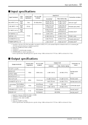
... Input terminals Gain trim Actual load impedance For use with nominal Input level Sensitivity1 Max. Unbalanced. (T=OUT, R=IN, S=GND) 5. before clip Connectors on mixer ST OUT 1, 2 (L/R) MONO OUT EFFECT SEND MONITOR OUT 1, 2 REC OUT (L/R) CH INSERT OUT (1-4) C-R/PHONES for PHONES OUT for C-R OUT SPEAKER OUT 1, 2 (L/R) BRIDGE OUT 150Ω 600Ω 100Ω 0.1Ω 600Ω Lines +4 dB (1.23 V) +20 dB (7.75 V) PHONE JACK...
... Input terminals Gain trim Actual load impedance For use with nominal Input level Sensitivity1 Max. Unbalanced. (T=OUT, R=IN, S=GND) 5. before clip Connectors on mixer ST OUT 1, 2 (L/R) MONO OUT EFFECT SEND MONITOR OUT 1, 2 REC OUT (L/R) CH INSERT OUT (1-4) C-R/PHONES for PHONES OUT for C-R OUT SPEAKER OUT 1, 2 (L/R) BRIDGE OUT 150Ω 600Ω 100Ω 0.1Ω 600Ω Lines +4 dB (1.23 V) +20 dB (7.75 V) PHONE JACK...

Owner's Manual
Page 23
EMX3000-Owner's Manual CH INPUT 1~4ch MIC INPUT [-60~-16dB] LINE INPUT [-34~+10dB] INSERT I/O [0dB] CH INPUT 5~8ch MIC INPUT [-60~-16dB] LINE INPUT [-34~+10dB] ST INPUT A L/MONO R 9/10ch • 11/12ch [-34~+10dB] L ST INPUT B R ST SUB IN 1-2 [+4dB] L/MONO R L TAPE IN [-10dBV] R PAD [26.5dB] PHANTOM (8ch/sw) +48V [0dB] HA 3-Stage EQ Hi Mid Lo GAIN (Trim) [-60dB~-16dB] [-34dB~+10dB] BA PEAK PAN [0dB] [0dB] BA...
EMX3000-Owner's Manual CH INPUT 1~4ch MIC INPUT [-60~-16dB] LINE INPUT [-34~+10dB] INSERT I/O [0dB] CH INPUT 5~8ch MIC INPUT [-60~-16dB] LINE INPUT [-34~+10dB] ST INPUT A L/MONO R 9/10ch • 11/12ch [-34~+10dB] L ST INPUT B R ST SUB IN 1-2 [+4dB] L/MONO R L TAPE IN [-10dBV] R PAD [26.5dB] PHANTOM (8ch/sw) +48V [0dB] HA 3-Stage EQ Hi Mid Lo GAIN (Trim) [-60dB~-16dB] [-34dB~+10dB] BA PEAK PAN [0dB] [0dB] BA...


