
Owner's Manual
Page 2
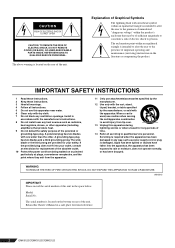
... Protect the power cord from being walked on the bottom or rear of the polarized or grounding-type plug. If the provided plug does not fit into the apparatus, the apparatus has been exposed to the presence of the unit. Model: Serial No.: The serial number is located on the rear of important operating and maintenance (servicing) instructions in the literature...
... Protect the power cord from being walked on the bottom or rear of the polarized or grounding-type plug. If the provided plug does not fit into the apparatus, the apparatus has been exposed to the presence of the unit. Model: Serial No.: The serial number is located on the rear of important operating and maintenance (servicing) instructions in the literature...
Owner's Manual
Page 3
... Yamaha service personnel. • Do not use of time at a high or uncomfortable volume level, since this manual in the vicinity of the connected devices, doing so may cause feedback and may damage the speakers. • Do not expose the device to be caused by qualified Yamaha service personnel. When turning the power off the power for all volume levels to minimum. • Use only speaker cables...
... Yamaha service personnel. • Do not use of time at a high or uncomfortable volume level, since this manual in the vicinity of the connected devices, doing so may cause feedback and may damage the speakers. • Do not expose the device to be caused by qualified Yamaha service personnel. When turning the power off the power for all volume levels to minimum. • Use only speaker cables...

Owner's Manual
Page 4
... found in all installation instructions. Compliance with the coloured markings identifying the termi- Utilize power outlets that interference will not result in harmful interference with this product to speed very quickly. ■ EMX Setup and Operation (starts on page 6) Presents a general explanation of this product in a residential environment will not occur in the users manual, may void your plug proceed as...
... found in all installation instructions. Compliance with the coloured markings identifying the termi- Utilize power outlets that interference will not result in harmful interference with this product to speed very quickly. ■ EMX Setup and Operation (starts on page 6) Presents a general explanation of this product in a residential environment will not occur in the users manual, may void your plug proceed as...
Owner's Manual
Page 5
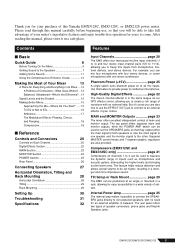
... MAIN Section 23 MONITOR Section 24 POWER Section 25 Rear Panel 26 Connecting Speakers 27 Horizontal Orientation, Tilting and Rack Mounting 28 Horizontal Orientation 28 Tilting 29 Rack Mounting 29 Setting Up 30 Troubleshooting 31 Specifications 32 Features Input Channels page 20 The EMX offers four monoaural mic/line input channels (1 to 4) and four stereo input channel pairs (5/6 to 11/12), allowing you to non-powered speakers, with no external help. Phantom Power (+15V page 25 A single switch turns phantom power...
... MAIN Section 23 MONITOR Section 24 POWER Section 25 Rear Panel 26 Connecting Speakers 27 Horizontal Orientation, Tilting and Rack Mounting 28 Horizontal Orientation 28 Tilting 29 Rack Mounting 29 Setting Up 30 Troubleshooting 31 Specifications 32 Features Input Channels page 20 The EMX offers four monoaural mic/line input channels (1 to 4) and four stereo input channel pairs (5/6 to 11/12), allowing you to non-powered speakers, with no external help. Phantom Power (+15V page 25 A single switch turns phantom power...
Owner's Manual
Page 6
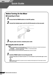
... source (starting with the closest). BASIC Quick Guide Before Turning On the Mixer ■ Connecting to Power 1 Be sure that the POWER switch is on. Rapidly turning the unit ON and OFF in to malfunction. For example: Sound source (external device) → EMX unit → Amps (Powered speakers) When turning power off , push the switch again, so that the LEVEL and MASTER knobs are set to the "0" position. 1 Push the POWER switch in succession...
... source (starting with the closest). BASIC Quick Guide Before Turning On the Mixer ■ Connecting to Power 1 Be sure that the POWER switch is on. Rapidly turning the unit ON and OFF in to malfunction. For example: Sound source (external device) → EMX unit → Amps (Powered speakers) When turning power off , push the switch again, so that the LEVEL and MASTER knobs are set to the "0" position. 1 Push the POWER switch in succession...
Owner's Manual
Page 7
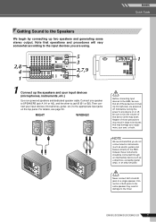
... using. 5 3 2,8 4 2,7,9 1 6 1 Connect up two speakers and generating some stereo output. And before turning the power to any device on the top panel. Connection of these precautions may result in damage to the mixer. BASIC Quick Guide Getting Sound to the Speakers We begin by connecting up the speakers and your input devices (microphones, instruments, etc.) Use non-powered speakers and dedicated speaker cable. NOTE We recommend that all the way down. Connect one speaker to SPEAKERS jack...
... using. 5 3 2,8 4 2,7,9 1 6 1 Connect up two speakers and generating some stereo output. And before turning the power to any device on the top panel. Connection of these precautions may result in damage to the mixer. BASIC Quick Guide Getting Sound to the Speakers We begin by connecting up the speakers and your input devices (microphones, instruments, etc.) Use non-powered speakers and dedicated speaker cable. NOTE We recommend that all the way down. Connect one speaker to SPEAKERS jack...
Owner's Manual
Page 9
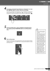
.../EMX212S 9 If you have connected a microphone or other mic-level device, set both MASTER knobs to the MIC position ( ). BASIC Quick Guide 5 If you are using one or more condenser microphones for your inputs, set the LINE/MIC switch on the power to all other than condenser microphones to phantom power. First turn on each channel accordingly. This precaution does not apply to balanced dynamic microphones, however, as a keyboard or audio device, set the channel's switch to 4, set the PHANTOM switch...
.../EMX212S 9 If you have connected a microphone or other mic-level device, set both MASTER knobs to the MIC position ( ). BASIC Quick Guide 5 If you are using one or more condenser microphones for your inputs, set the LINE/MIC switch on the power to all other than condenser microphones to phantom power. First turn on each channel accordingly. This precaution does not apply to balanced dynamic microphones, however, as a keyboard or audio device, set the channel's switch to 4, set the PHANTOM switch...

Owner's Manual
Page 13
... in , twiddle the controls, and away you 're ready to use this type of connector when connecting a CD player or other home audio type source to as "phono" jacks (short for "phonogram"), but if this is also often referred to as will the owner's manual (you do keep your mixer, or when connecting the output of Your Mixer An Introduction You've...
... in , twiddle the controls, and away you 're ready to use this type of connector when connecting a CD player or other home audio type source to as "phono" jacks (short for "phonogram"), but if this is also often referred to as will the owner's manual (you do keep your mixer, or when connecting the output of Your Mixer An Introduction You've...
Owner's Manual
Page 15
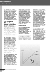
... be required to handle signals at their nominal settings, but it's too easy to start with all faders at a wide range of levels, and it a song in a doubling or halving of the loudness. In most commonly used units in the owner's manual. Mixing is 120 dB. The inputs and outputs on home-use audio gear usually have inputs and outputs with a nominal level of +4 dBu. There...
... be required to handle signals at their nominal settings, but it's too easy to start with all faders at a wide range of levels, and it a song in a doubling or halving of the loudness. In most commonly used units in the owner's manual. Mixing is 120 dB. The inputs and outputs on home-use audio gear usually have inputs and outputs with a nominal level of +4 dBu. There...
Owner's Manual
Page 17
... falling into clarity. Use your sound clean. Reverb Level It's amazing how quickly your mix. Naturally you 'll want the "snap" of a bass guitar, for example, try setting the delay time to dotted eighth notes corresponding to the tune's tempo. On the EMX mixers these effects are cluttering up -tempo tunes. Delay times can be adjusted via the panel PARAMETER control. You'll have a significant effect on the music's demo and...
... falling into clarity. Use your sound clean. Reverb Level It's amazing how quickly your mix. Naturally you 'll want the "snap" of a bass guitar, for example, try setting the delay time to dotted eighth notes corresponding to the tune's tempo. On the EMX mixers these effects are cluttering up -tempo tunes. Delay times can be adjusted via the panel PARAMETER control. You'll have a significant effect on the music's demo and...
Owner's Manual
Page 18
... EMX compressor makes achieving great sound much easier. For phasing effects the shift is "time-shifted" and then mixed back with the direct signal. a difference measured in terms of thing you're aiming for you ever wondered why professionally produced recordings sound so different from your own? Phasing is the subtlest of all these effects work on a considerable amount of experience, to set a single "compression" control...
... EMX compressor makes achieving great sound much easier. For phasing effects the shift is "time-shifted" and then mixed back with the direct signal. a difference measured in terms of thing you're aiming for you ever wondered why professionally produced recordings sound so different from your own? Phasing is the subtlest of all these effects work on a considerable amount of experience, to set a single "compression" control...
Owner's Manual
Page 20
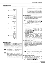
... a performance. Setting the knob to adjust the volume balance among the various channels. Use these lamps when setting up , adjust the channels equalizer 2 or level knob 5 to reduce the level so that might be output from the SPEAKERS A jacks V (depending on the level of the signal sent into the MONITOR bus. 4 EFFECT knob Adjusts the level of the channel's signal into the MONITOR bus. NOTE To reduce noise, set the knobs for each of the POWER AMP switch R). The...
... a performance. Setting the knob to adjust the volume balance among the various channels. Use these lamps when setting up , adjust the channels equalizer 2 or level knob 5 to reduce the level so that might be output from the SPEAKERS A jacks V (depending on the level of the signal sent into the MONITOR bus. 4 EFFECT knob Adjusts the level of the channel's signal into the MONITOR bus. NOTE To reduce noise, set the knobs for each of the POWER AMP switch R). The...
Owner's Manual
Page 21
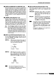
... adjusts the level of loud noises that could cause hearing loss or device damage. 8 INPUT A and INPUT B jacks (Channels 1 to 4) You can connect an input source to either a mic-level (low level) signal or a line-level (high level) signal. R: Cold (-) 9 LINE and MIC jacks (Channels 5/6 to connect up a microphone or other power amplifiers and power speakers before operating the switch, to avoid risk of compression applied to its ON position. If you are supplying-either jack. Use these are connecting up stereo output...
... adjusts the level of loud noises that could cause hearing loss or device damage. 8 INPUT A and INPUT B jacks (Channels 1 to 4) You can connect an input source to either a mic-level (low level) signal or a line-level (high level) signal. R: Cold (-) 9 LINE and MIC jacks (Channels 5/6 to connect up a microphone or other power amplifiers and power speakers before operating the switch, to avoid risk of compression applied to its ON position. If you are supplying-either jack. Use these are connecting up stereo output...
Owner's Manual
Page 22
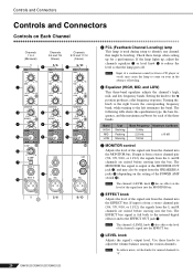
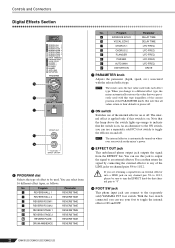
... internal effect is applied only if this jack to output the signal to an external effector. With the foot switch connected, you are returning a signal from an external effector into a LINE jack on the mixer's power. NOTE The mixer saves the last value used with the selected effect type. Program 1 REVERB HALL 1 2 REVERB HALL 2 3 REVERB ROOM 1 4 REVERB ROOM 2 5 REVERB STAGE 1 6 REVERB STAGE 2 7 REVERB PLATE 8 DRUM AMBIENCE Parameter REVERB TIME REVERB TIME REVERB TIME REVERB TIME REVERB TIME REVERB TIME REVERB TIME REVERB TIME No. Controls and Connectors Digital...
... internal effect is applied only if this jack to output the signal to an external effector. With the foot switch connected, you are returning a signal from an external effector into a LINE jack on the mixer's power. NOTE The mixer saves the last value used with the selected effect type. Program 1 REVERB HALL 1 2 REVERB HALL 2 3 REVERB ROOM 1 4 REVERB ROOM 2 5 REVERB STAGE 1 6 REVERB STAGE 2 7 REVERB PLATE 8 DRUM AMBIENCE Parameter REVERB TIME REVERB TIME REVERB TIME REVERB TIME REVERB TIME REVERB TIME REVERB TIME REVERB TIME No. Controls and Connectors Digital...
Owner's Manual
Page 25
... phantom power. • When using one or more condenser microphones. Down (MAIN(L+R)/MON): SPEAKERS jacks A1 and A2 output a mix of damage to "0". S YS Processing switch This switch turns Yamaha Speaker Processing on or off . T STAND-BY switch This switch mutes the input to channels 1 to the B jacks. NOTE When using the mixer for lack of loud noises that the power in the performance by phantom power. • To avoid damage to speakers, be sure to turn both MASTER...
... phantom power. • When using one or more condenser microphones. Down (MAIN(L+R)/MON): SPEAKERS jacks A1 and A2 output a mix of damage to "0". S YS Processing switch This switch turns Yamaha Speaker Processing on or off . T STAND-BY switch This switch mutes the input to channels 1 to the B jacks. NOTE When using the mixer for lack of loud noises that the power in the performance by phantom power. • To avoid damage to speakers, be sure to turn both MASTER...
Owner's Manual
Page 26
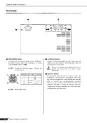
... shown below. 1- 1+ Neutrik Plug A1 and B1 Connectors 1+ + 1- - 2+ 2+ 2- 2- W AC IN connector Connects to the included power cord. Use of a different cord may pose risk of fire, burns, or equipment damage. Please use the cord that the output directed to these jacks to connect to speakers. If the AC outlet is inserted into a standard power outlet. Controls and Connectors Rear Panel W V X V SPEAKERS jacks Use these jacks varies according to the setting of the POWER AMP switch R.
... shown below. 1- 1+ Neutrik Plug A1 and B1 Connectors 1+ + 1- - 2+ 2+ 2- 2- W AC IN connector Connects to the included power cord. Use of a different cord may pose risk of fire, burns, or equipment damage. Please use the cord that the output directed to these jacks to connect to speakers. If the AC outlet is inserted into a standard power outlet. Controls and Connectors Rear Panel W V X V SPEAKERS jacks Use these jacks varies according to the setting of the POWER AMP switch R.
Owner's Manual
Page 30
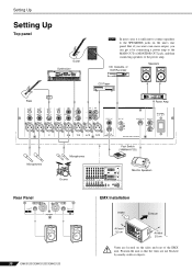
...ficient to connect speakers to the power amp. Setting Up Setting Up Top panel Guitar OCTAVE DOWN UP Synthesizer PAN / SEND ASSIGN TONE KNOB CONTROL FUNCTION ÊARP FX EQ ASSIGN A PAN CUTOFF SWING ASSIGN B REVERB RESONANCE GATE TIME ASSIGN 1 CHORUS ATTACK VELOCITY ASSIGN 2 TEMPO RELEASE UNITMULTIPLY KN 1 LOW VOLUME 1 KN 2 LOW MID VOLUME 2 KN 3 HIGH MID VOLUME 3 KN 4 HIGH VOLUME 4 REMOTE ARPEGGIO R-AUDIO ON/OFF G-MIDI ON/OFF EFFECT BYPASS INSERTION SYSTEM MASTER EFFECT SEQ TRANSPORT LOCATE 1 2 MASTER VOLUME CS 1 ZONE...
...ficient to connect speakers to the power amp. Setting Up Setting Up Top panel Guitar OCTAVE DOWN UP Synthesizer PAN / SEND ASSIGN TONE KNOB CONTROL FUNCTION ÊARP FX EQ ASSIGN A PAN CUTOFF SWING ASSIGN B REVERB RESONANCE GATE TIME ASSIGN 1 CHORUS ATTACK VELOCITY ASSIGN 2 TEMPO RELEASE UNITMULTIPLY KN 1 LOW VOLUME 1 KN 2 LOW MID VOLUME 2 KN 3 HIGH MID VOLUME 3 KN 4 HIGH VOLUME 4 REMOTE ARPEGGIO R-AUDIO ON/OFF G-MIDI ON/OFF EFFECT BYPASS INSERTION SYSTEM MASTER EFFECT SEQ TRANSPORT LOCATE 1 2 MASTER VOLUME CS 1 ZONE...

Owner's Manual
Page 31
..., and LOW knobs) on each channel. ❑ Adjust the graphic equalizers. ■ I want to send the monitor signal to SPEAKERS jacks B1 and B2, set the POWER AMP switch to the down . ■ No sound. ❑ Are microphones, external devices, and speakers connected correctly? ❑ Are the channel LEVEL knobs and the two MASTER knobs set appropriately. ❑ Check that the LINE/MIC switches on channels 1 to 4 are blocked. Wait for a list of Yamaha dealers.) ■ Sound is faint...
..., and LOW knobs) on each channel. ❑ Adjust the graphic equalizers. ■ I want to send the monitor signal to SPEAKERS jacks B1 and B2, set the POWER AMP switch to the down . ■ No sound. ❑ Are microphones, external devices, and speakers connected correctly? ❑ Are the channel LEVEL knobs and the two MASTER knobs set appropriately. ❑ Check that the LINE/MIC switches on channels 1 to 4 are blocked. Wait for a list of Yamaha dealers.) ■ Sound is faint...
Owner's Manual
Page 32
... 100 (shelving) Internal Digital Effect 16 programs Parameter control FOOT SW ON/OFF Level Meters 2 × 5-points LED level meter [MAIN(L,R)], 5-points LED level meter [MONITOR] +6, +3, 0, -5, -10 [dB] FCL Sensitivity Protection Input signal level => -75dBu: LED on, CH1-4 MIC/LINE:MIC B Input, CH 5/6-11/12 MIC Input Power Amplifier POWER switch on/off mute DC-fault :power supply shutdown /manual reset Thermal /heatsink temp => 90˚C:output mute /auto reset Vl limiter /RL =< 2 Clip limiter /THD Ω => 1 %, Indicator × 2 Power Supply Thermal /heatsink...
... 100 (shelving) Internal Digital Effect 16 programs Parameter control FOOT SW ON/OFF Level Meters 2 × 5-points LED level meter [MAIN(L,R)], 5-points LED level meter [MONITOR] +6, +3, 0, -5, -10 [dB] FCL Sensitivity Protection Input signal level => -75dBu: LED on, CH1-4 MIC/LINE:MIC B Input, CH 5/6-11/12 MIC Input Power Amplifier POWER switch on/off mute DC-fault :power supply shutdown /manual reset Thermal /heatsink temp => 90˚C:output mute /auto reset Vl limiter /RL =< 2 Clip limiter /THD Ω => 1 %, Indicator × 2 Power Supply Thermal /heatsink...
Owner's Manual
Page 33
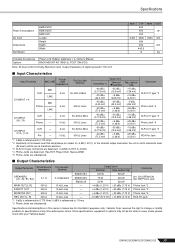
...-3-31 type *3 Phone Jack *5 CH INPUT 9/10, 11/12 XLR - Since specifications, equipment or options may not be the same in this owner's manual are unbalanced. ■ Output Characteristics Output Terminals Actual Source Impedance For Use with Nominal SPEAKERS [A1, A2, B1, B2] 0.1 Ω 4 Ω Speakers EMX512SC EMX312SC EMX212S MAIN OUT [L, R] 600 Ω 10 kΩ Lines - reserves the right to change or modify products...
...-3-31 type *3 Phone Jack *5 CH INPUT 9/10, 11/12 XLR - Since specifications, equipment or options may not be the same in this owner's manual are unbalanced. ■ Output Characteristics Output Terminals Actual Source Impedance For Use with Nominal SPEAKERS [A1, A2, B1, B2] 0.1 Ω 4 Ω Speakers EMX512SC EMX312SC EMX212S MAIN OUT [L, R] 600 Ω 10 kΩ Lines - reserves the right to change or modify products...


