

Dme-n Network Driver For Dsp5d Installation Guide
Page 4
...Driver will be aborted. The "Add or Remove Programs" dialog box appears. 2 Click [Remove] for DSP5D 4 The installer should run normally after your computer has been restarted. n If you attempt to reinstall the...and click [Finish]. "Restart your computer, then run the installer." "***" represents the version number. 3 Double-click on "setup.exe." Click [Continue]. 4 Click [Next]. The computer will be installed. Uninstalling Windows XP 1 Select [Start] &#... a program" dialog box appears. 2 Select "Yamaha DME-N Network Driver" and click [Uninstall]. Click [Continue].
...Driver will be aborted. The "Add or Remove Programs" dialog box appears. 2 Click [Remove] for DSP5D 4 The installer should run normally after your computer has been restarted. n If you attempt to reinstall the...and click [Finish]. "Restart your computer, then run the installer." "***" represents the version number. 3 Double-click on "setup.exe." Click [Continue]. 4 Click [Next]. The computer will be installed. Uninstalling Windows XP 1 Select [Start] &#... a program" dialog box appears. 2 Select "Yamaha DME-N Network Driver" and click [Uninstall]. Click [Continue].

Dme-n Network Driver For Dsp5d Installation Guide
Page 5
...for Windows 7 Click [View by : Category] in the upper left of the control panel, and select "Large icons" or "Small icons". for DSP5D 5 message will appear. 3 If the control panel appears as category view, switch the view as follows: For Windows XP Click [Switch to "...-N Network Driver settings cannot be changed while any application that use the DME-N Network Driver, the computer and the DSP5D must be properly connected and configured. Setup 1 Log onto Windows with Administrator privileges. The "Control Panel" will appear. For details on configuration, ...
...for Windows 7 Click [View by : Category] in the upper left of the control panel, and select "Large icons" or "Small icons". for DSP5D 5 message will appear. 3 If the control panel appears as category view, switch the view as follows: For Windows XP Click [Switch to "...-N Network Driver settings cannot be changed while any application that use the DME-N Network Driver, the computer and the DSP5D must be properly connected and configured. Setup 1 Log onto Windows with Administrator privileges. The "Control Panel" will appear. For details on configuration, ...

Dme-n Network Driver For Dsp5d Installation Guide
Page 7
...Network Driver is cascade-connected to the PM5D. parameters to your computer via Ethernet" of the DSP5D owner's manual and "Console Setup" of the PM5DV2/DSP5D Editor owner's manual. DME-N Network Driver Installation Guide for DSP5D. [Undo] Button This button provides a one-step undo function that allows you want to ...undo operation or after editing the Device Name, Device IP Address, Device MAC Address, or Device Port No. The MAC address of the DSP5D can be viewed and edited in the PREFERENCE 2 screen on the default value of the device selected in the Device Name field...
...Network Driver is cascade-connected to the PM5D. parameters to your computer via Ethernet" of the DSP5D owner's manual and "Console Setup" of the PM5DV2/DSP5D Editor owner's manual. DME-N Network Driver Installation Guide for DSP5D. [Undo] Button This button provides a one-step undo function that allows you want to ...undo operation or after editing the Device Name, Device IP Address, Device MAC Address, or Device Port No. The MAC address of the DSP5D can be viewed and edited in the PREFERENCE 2 screen on the default value of the device selected in the Device Name field...

Dme-n Network Driver For Dsp5d Installation Guide
Page 8
...automatic detection. DME-N Network Driver Installation Guide for automatic device detection, and allow saving and loading setup files. 1 2 5 3 4 6 7 8 9 ) Auto Detect Allows automatic detection of the DSP5D owner's manual. n Only MAC addresses of the DSP5D and the computer must have been assigned properly. n In order to your computer via Ethernet" of... searched, and that an appropriate IP address is not in the "Advanced Settings" dialog box set up the DME-N Network Driver for DSP5D 8 Advanced Setup The "Advanced Settings" dialog box can be updated accordingly.
...automatic detection. DME-N Network Driver Installation Guide for automatic device detection, and allow saving and loading setup files. 1 2 5 3 4 6 7 8 9 ) Auto Detect Allows automatic detection of the DSP5D owner's manual. n Only MAC addresses of the DSP5D and the computer must have been assigned properly. n In order to your computer via Ethernet" of... searched, and that an appropriate IP address is not in the "Advanced Settings" dialog box set up the DME-N Network Driver for DSP5D 8 Advanced Setup The "Advanced Settings" dialog box can be updated accordingly.

Dme-n Network Driver For Dsp5d Installation Guide
Page 9
...detected device. Device Name If a name has been registered for DSP5D 9 Click to load a previously saved setup file. Select a setup file and then click the [Open] button to import the corresponding settings. ) [Export Setup to File] Button It is possible to open the "Open .... Click to Device List] button (below) is clicked. 8 [Cancel] Button Closes the dialog box without making any changes. 9 [Import Setup from File] Button When working in a different environment it will be displayed here, otherwise no name will be checked. DME-N Network Driver Installation...
...detected device. Device Name If a name has been registered for DSP5D 9 Click to load a previously saved setup file. Select a setup file and then click the [Open] button to import the corresponding settings. ) [Export Setup to File] Button It is possible to open the "Open .... Click to Device List] button (below) is clicked. 8 [Cancel] Button Closes the dialog box without making any changes. 9 [Import Setup from File] Button When working in a different environment it will be displayed here, otherwise no name will be checked. DME-N Network Driver Installation...
Dme-n Network Driver For Dsp5d Installation Guide
Page 12
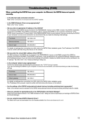
... controlling the DSP5D from the Yamaha website http://www.yamahaproaudio.com/ DME-N Network Driver Installation Guide for details. • Have you selected an appropriate ports in a one-to-one connection, we recommend that you are connecting the DSP5D to your computer via Ethernet" of the DSP5D owner's manual and "Console Setup" of the DSP5D? Refer to...
... controlling the DSP5D from the Yamaha website http://www.yamahaproaudio.com/ DME-N Network Driver Installation Guide for details. • Have you selected an appropriate ports in a one-to-one connection, we recommend that you are connecting the DSP5D to your computer via Ethernet" of the DSP5D owner's manual and "Console Setup" of the DSP5D? Refer to...
Dsp5d Editor Installation Guide
Page 5
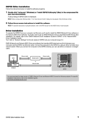
... DME-N Network Driver and Network-MIDI Driver at the following website. n When running under Windows Vista / 7, the "User Account Control" dialog box may appear. A setup dialog of DSP5D and your computer (page 6.) DME-N Network and Network-MIDI Driver are software that transfers MIDI data back and forth between your computer via a network...
... DME-N Network Driver and Network-MIDI Driver at the following website. n When running under Windows Vista / 7, the "User Account Control" dialog box may appear. A setup dialog of DSP5D and your computer (page 6.) DME-N Network and Network-MIDI Driver are software that transfers MIDI data back and forth between your computer via a network...

Dsp5d Editor Installation Guide
Page 8
... icon for each Editor. For Mac OS X: Select and open the "Applications" folder, the "YAMAHA" folder, then the "StudioManager" folder, then doubleclick "SM2." 2 Set up each Editor. DSP5D Editor Installation Guide 8 Studio Manager window 4 Set up Studio Manager. Starting and setting up Studio Manager... You'll need to perform the following setup in order to use the Editors in Studio Manager. 1 Start up...
... icon for each Editor. For Mac OS X: Select and open the "Applications" folder, the "YAMAHA" folder, then the "StudioManager" folder, then doubleclick "SM2." 2 Set up each Editor. DSP5D Editor Installation Guide 8 Studio Manager window 4 Set up Studio Manager. Starting and setting up Studio Manager... You'll need to perform the following setup in order to use the Editors in Studio Manager. 1 Start up...

Dsp5d Editor Installation Guide
Page 9
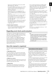
...When you connect the computer to the DSP5D directly, you might experience problems controlling DSP5D DME-N Network Driver Installation Guide for DSP5D, Network-MIDI Driver Installation Guide • Is the computer network setup appropriate? Did you selected an appropriate network... IP address DME-N Network Driver Installation Guide for DSP5D, Network-MIDI Driver Installation Guide DSP5D Editor Installation Guide U.R.G., Pro Audio Division © 2007-2010 Yamaha Corporation 007MW-B0 9 Troubleshooting When controlling the DSP5D from your computer via a network switch or router...
...When you connect the computer to the DSP5D directly, you might experience problems controlling DSP5D DME-N Network Driver Installation Guide for DSP5D, Network-MIDI Driver Installation Guide • Is the computer network setup appropriate? Did you selected an appropriate network... IP address DME-N Network Driver Installation Guide for DSP5D, Network-MIDI Driver Installation Guide DSP5D Editor Installation Guide U.R.G., Pro Audio Division © 2007-2010 Yamaha Corporation 007MW-B0 9 Troubleshooting When controlling the DSP5D from your computer via a network switch or router...

Owner's Manual
Page 6
...fader 29 Assigning a name 30 4 Connections and setup 31 Examples of systems expanded with the DSP5D 31 Example of simple input expansion (PM5D + one DSP5D unit 31 PM5D + remotely connected input expansion (PM5D + DCU5D + two DSP5D units 31 Control from DSP5D Editor (one DSP5D unit + PC 32 Audio connections 33 Analog ... clock master 38 Restoring the current scene to the default state 40 Switching the target of panel operations (when cascade-connected with the DSP5D) ........ 40 5 Input channel operations 41 About the input channels 41 AD IN section 43 Items in the AD IN section 43...
...fader 29 Assigning a name 30 4 Connections and setup 31 Examples of systems expanded with the DSP5D 31 Example of simple input expansion (PM5D + one DSP5D unit 31 PM5D + remotely connected input expansion (PM5D + DCU5D + two DSP5D units 31 Control from DSP5D Editor (one DSP5D unit + PC 32 Audio connections 33 Analog ... clock master 38 Restoring the current scene to the default state 40 Switching the target of panel operations (when cascade-connected with the DSP5D) ........ 40 5 Input channel operations 41 About the input channels 41 AD IN section 43 Items in the AD IN section 43...

Owner's Manual
Page 8
...FADE TIME screen 184 TRACKING RECALL screen 186 GLOBAL PASTE screen 187 MIDI REMOTE function 188 MIDI SETUP screen 188 MIDI PGM CHANGE (MIDI program change) screen ........190 MIDI CTRL CHANGE (MIDI ... FADER ASSIGN screen 217 SECURITY screen 218 SYS/W.CLOCK function 219 WORD CLOCK screen 219 MIXER SETUP screen 221 CASCADE screen 226 HA (Head Amp) screen 228 OUTPUT PORT ATT (Output port... function 262 MATRIX/ST ROUTING screen 262 MIX to MATRIX VIEW screen 264 LCR screen 267 SURR SETUP screen 268 OUTPUT VIEW function 270 CH VIEW (Channel view) screen 270 SIGNAL FLOW screen 272...
...FADE TIME screen 184 TRACKING RECALL screen 186 GLOBAL PASTE screen 187 MIDI REMOTE function 188 MIDI SETUP screen 188 MIDI PGM CHANGE (MIDI program change) screen ........190 MIDI CTRL CHANGE (MIDI ... FADER ASSIGN screen 217 SECURITY screen 218 SYS/W.CLOCK function 219 WORD CLOCK screen 219 MIXER SETUP screen 221 CASCADE screen 226 HA (Head Amp) screen 228 OUTPUT PORT ATT (Output port... function 262 MATRIX/ST ROUTING screen 262 MIX to MATRIX VIEW screen 264 LCR screen 267 SURR SETUP screen 268 OUTPUT VIEW function 270 CH VIEW (Channel view) screen 270 SIGNAL FLOW screen 272...

Owner's Manual
Page 14
...; Major new functionality in PM5D firmware V2.0 The major new functionality and improvements that were added in SETUP memory (which is now faster. http://www.yamahaproaudio.com/ For either the PM5D or the DSP5D, you to firmware V2.0 are transmitted when the scene is recalled. (➥ p.175) • In...off when you remove the GEQ. ❏ SCENE functions • In the SCENE screen, you can download the most recent firmware from the following Yamaha website. You can now assign these to the faders of the DCA strip so that the monitor or cue levels can be adjusted. (➥ p.149...
...; Major new functionality in PM5D firmware V2.0 The major new functionality and improvements that were added in SETUP memory (which is now faster. http://www.yamahaproaudio.com/ For either the PM5D or the DSP5D, you to firmware V2.0 are transmitted when the scene is recalled. (➥ p.175) • In...off when you remove the GEQ. ❏ SCENE functions • In the SCENE screen, you can download the most recent firmware from the following Yamaha website. You can now assign these to the faders of the DCA strip so that the monitor or cue levels can be adjusted. (➥ p.149...
Owner's Manual
Page 15
...those that you to use the STEREO/DCA strip section to control the monitor/cue level and on the front and rear panels, connections and setup, and how to the Reference Section "WORD CLOCK screen" (➥ p.219). • As an exception, digital signals that are called "word...following three sections. ❏ Operating section This section explains the items on /off status when you push them from an external device via the PM5D/DSP5D's digital input/output jacks or via a digital I /O card that you to a maximum value are called "encoders." How this section when you can...
...those that you to use the STEREO/DCA strip section to control the monitor/cue level and on the front and rear panels, connections and setup, and how to the Reference Section "WORD CLOCK screen" (➥ p.219). • As an exception, digital signals that are called "word...following three sections. ❏ Operating section This section explains the items on /off status when you push them from an external device via the PM5D/DSP5D's digital input/output jacks or via a digital I /O card that you to a maximum value are called "encoders." How this section when you can...

Owner's Manual
Page 31
...pin cable, each connected from the PM5D's panel (➥ p.40). 4 Connections and setup This chapter describes examples of expanded systems using the DSP5D, audio input/output connections, and the setup that will be the target of control from CASCADE IN to select the PM5D...make cascade connection settings (➥ p.154). Examples of systems expanded with the DSP5D 4 • In order to use "cascade connections" for the first time. Connections and setup Example of simple input expansion (PM5D + one DSP5D unit) • This system expands the number of input channels to 96...
...pin cable, each connected from the PM5D's panel (➥ p.40). 4 Connections and setup This chapter describes examples of expanded systems using the DSP5D, audio input/output connections, and the setup that will be the target of control from CASCADE IN to select the PM5D...make cascade connection settings (➥ p.154). Examples of systems expanded with the DSP5D 4 • In order to use "cascade connections" for the first time. Connections and setup Example of simple input expansion (PM5D + one DSP5D unit) • This system expands the number of input channels to 96...

Owner's Manual
Page 32
4 Connections and setup Control from DSP5D Editor (one DSP5D unit + PC) • One DSP5D unit is connected to a PC via an Ethernet CAT5 cable, allowing the DSP5D to be controlled from DSP5D Editor. Ethernet CAT5 CASCADE IN DSP5D PC 32 PM5D/PM5D-RH V2 / DSP5D Owner's Manual Operating section
4 Connections and setup Control from DSP5D Editor (one DSP5D unit + PC) • One DSP5D unit is connected to a PC via an Ethernet CAT5 cable, allowing the DSP5D to be controlled from DSP5D Editor. Ethernet CAT5 CASCADE IN DSP5D PC 32 PM5D/PM5D-RH V2 / DSP5D Owner's Manual Operating section

Owner's Manual
Page 33
Audio connections Analog audio connections PM5D model Synthesizer Microphone DSP5D Microphone Synthesizer 4 Connections and setup Effect processor INPUT jacks 1-48 are used mainly to...this if desired (for details on the PM5D-RH (➥ p.44). When the PM5D, PM5D-RH, or DSP5D are controlled from the display as a whole by the rear panel [+48V MASTER] switch. INPUT jacks 1-48... phantom power can be operated from within the display (➥ p.44). PM5D/PM5D-RH V2 / DSP5D Owner's Manual Operating section 33 Input signal sensitivity, pad on/off, and phantom power (+48V) on /...
Audio connections Analog audio connections PM5D model Synthesizer Microphone DSP5D Microphone Synthesizer 4 Connections and setup Effect processor INPUT jacks 1-48 are used mainly to...this if desired (for details on the PM5D-RH (➥ p.44). When the PM5D, PM5D-RH, or DSP5D are controlled from the display as a whole by the rear panel [+48V MASTER] switch. INPUT jacks 1-48... phantom power can be operated from within the display (➥ p.44). PM5D/PM5D-RH V2 / DSP5D Owner's Manual Operating section 33 Input signal sensitivity, pad on/off, and phantom power (+48V) on /...

Owner's Manual
Page 34
4 Connections and setup Analog output connections PM5D/PM5D-RH Monitor speakers Monitor speakers PW800W power supply MIX OUT MONITOR OUT CUE OUT C R L R L R L R L 8 7 6 5 4 3 2 1 DC POWER INPUT LA MATRIX OUT .... The CUE OUT jacks output the cue monitor signal of the channel that is currently selected by its [CUE] key. 34 PM5D/PM5D-RH V2 / DSP5D Owner's Manual Operating section
4 Connections and setup Analog output connections PM5D/PM5D-RH Monitor speakers Monitor speakers PW800W power supply MIX OUT MONITOR OUT CUE OUT C R L R L R L R L 8 7 6 5 4 3 2 1 DC POWER INPUT LA MATRIX OUT .... The CUE OUT jacks output the cue monitor signal of the channel that is currently selected by its [CUE] key. 34 PM5D/PM5D-RH V2 / DSP5D Owner's Manual Operating section

Owner's Manual
Page 35
...'s Manual Operating section 35 the signals of the STEREO A channel are output from OMNI OUT jacks 1-24. DSP5D Monitor speakers (foldback) 4 Connections and setup CASCADE IN OUT IN 75Ω TERMINATED OUT IN OUT IN TX RX TX RX Main speakers PW800W power supply (for backup external power supply) ...
...'s Manual Operating section 35 the signals of the STEREO A channel are output from OMNI OUT jacks 1-24. DSP5D Monitor speakers (foldback) 4 Connections and setup CASCADE IN OUT IN 75Ω TERMINATED OUT IN OUT IN TX RX TX RX Main speakers PW800W power supply (for backup external power supply) ...

Owner's Manual
Page 36
... slots 1-4, the word clock data of channels Digital format Bit depth 16 EtherSound 24 bit 8 ADAT 24bit * is supported only by the PM5D. 4 Connections and setup Digital input/output connections R L R L N SMPTE USB OUT IN 75 ON OFF 2 1 2 1 3 3 COAXIAL AES/EBU AES/EBU COAXIAL AES/EBU AES/EBU ...jacks, or slots 1-4 to input channels or ST IN channels, you will need to the PM5D/DSP5D or allow connection of channels 4 8 4 8 8 8 16 8 16 8 16 16 16 16 Digital format - - - The following Yamaha website. Card type Model MY4-AD AD card MY8-AD* MY8-AD24 MY8-AD96 DA card ...
... slots 1-4, the word clock data of channels Digital format Bit depth 16 EtherSound 24 bit 8 ADAT 24bit * is supported only by the PM5D. 4 Connections and setup Digital input/output connections R L R L N SMPTE USB OUT IN 75 ON OFF 2 1 2 1 3 3 COAXIAL AES/EBU AES/EBU COAXIAL AES/EBU AES/EBU ...jacks, or slots 1-4 to input channels or ST IN channels, you will need to the PM5D/DSP5D or allow connection of channels 4 8 4 8 8 8 16 8 16 8 16 16 16 16 Digital format - - - The following Yamaha website. Card type Model MY4-AD AD card MY8-AD* MY8-AD24 MY8-AD96 DA card ...

Owner's Manual
Page 37
...setup 2 1 U 3 AES/EBU 2 COAXIAL 1 AES/EBU AES/EBU 3 Align the edges of the card is correctly mated with the connector inside the slot, and insert the card into the slot so that can be installed in conjunction with the card to fasten the card in place. PM5D/PM5D-RH V2 / DSP5D... Owner's Manual Operating section 37 Malfunctions or incorrect operation may occur if the card is turned off. 2 Loosen the screws that hold the slot cover in a safe place. Push the card all the way into the slot. Installing an option card Before installing a card, you must check the Yamaha website...
...setup 2 1 U 3 AES/EBU 2 COAXIAL 1 AES/EBU AES/EBU 3 Align the edges of the card is correctly mated with the connector inside the slot, and insert the card into the slot so that can be installed in conjunction with the card to fasten the card in place. PM5D/PM5D-RH V2 / DSP5D... Owner's Manual Operating section 37 Malfunctions or incorrect operation may occur if the card is turned off. 2 Loosen the screws that hold the slot cover in a safe place. Push the card all the way into the slot. Installing an option card Before installing a card, you must check the Yamaha website...

