
Dsp5d Editor Installation Guide
Page 5
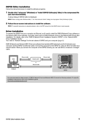
... you connect the computer to the DSP5D directly, you 'll need to the "DME-N Network Driver Installation Guide for the set up DME-N Network Driver or the Network-MIDI Driver after installation. For specific installation instructions, refer to install the software. DSP5D Editor Installation Follow the instructions below to install the software programs. 1 Double-click "setup.exe" (Windows) or "Install DSP5D Editor.pkg" (Mac) in each program. Editor Driver Computer Ethernet cable Network switch or Ethernet cable Ethernet cable DSP5D You can use...
... you connect the computer to the DSP5D directly, you 'll need to the "DME-N Network Driver Installation Guide for the set up DME-N Network Driver or the Network-MIDI Driver after installation. For specific installation instructions, refer to install the software. DSP5D Editor Installation Follow the instructions below to install the software programs. 1 Double-click "setup.exe" (Windows) or "Install DSP5D Editor.pkg" (Mac) in each program. Editor Driver Computer Ethernet cable Network switch or Ethernet cable Ethernet cable DSP5D You can use...

Owner's Manual
Page 6
... output connections 34 Digital input/output connections 36 Installing an option card 37 Word clock connections and settings 38 About word clock 38 Selecting the word clock master 38 Restoring the current scene to the default state 40 Switching the target of panel operations (when cascade-connected with the DSP5D) ........ 40 5 Input channel operations 41 About the input channels 41 AD IN section 43 Items in the AD IN section 43 Controlling the input sensitivity and phantom power (+48V) of the head amp...
... output connections 34 Digital input/output connections 36 Installing an option card 37 Word clock connections and settings 38 About word clock 38 Selecting the word clock master 38 Restoring the current scene to the default state 40 Switching the target of panel operations (when cascade-connected with the DSP5D) ........ 40 5 Input channel operations 41 About the input channels 41 AD IN section 43 Items in the AD IN section 43 Controlling the input sensitivity and phantom power (+48V) of the head amp...

Owner's Manual
Page 7
... metering point for output channels 109 Viewing the gain reduction of the internal gates and compressors 110 Viewing the gain reduction for input channels 110 Viewing the gain reduction for output channels 110 14 Effects 111 About the internal effects 111 Using an internal effect via a MIX bus 112 Inserting an internal effect into a channel 113 Basic operations in the effect screen 114 Recalling settings from the effect library 114 Editing the effect parameters 115 Storing settings in the effect library 115 Using the Tap Tempo function...
... metering point for output channels 109 Viewing the gain reduction of the internal gates and compressors 110 Viewing the gain reduction for input channels 110 Viewing the gain reduction for output channels 110 14 Effects 111 About the internal effects 111 Using an internal effect via a MIX bus 112 Inserting an internal effect into a channel 113 Basic operations in the effect screen 114 Recalling settings from the effect library 114 Editing the effect parameters 115 Storing settings in the effect library 115 Using the Tap Tempo function...

Owner's Manual
Page 10
... (delay, EQ, gate, compressor) of applications. AD cards, DA cards, or digital I /O card expansion The rear panel provides four slots in . After you have read this manual before you can be used in various libraries, independently of two DSP5D digital mixing systems can be controlled by the eight DCA faders on the panel, and use them as on /off controls. Effects, input/output patching, input channel/output channel settings, internal head amp (PM5D-RH model only) or external head amp settings can...
... (delay, EQ, gate, compressor) of applications. AD cards, DA cards, or digital I /O card expansion The rear panel provides four slots in . After you have read this manual before you can be used in various libraries, independently of two DSP5D digital mixing systems can be controlled by the eight DCA faders on the panel, and use them as on /off controls. Effects, input/output patching, input channel/output channel settings, internal head amp (PM5D-RH model only) or external head amp settings can...
Owner's Manual
Page 15
... the internal effects, the MIDI data format, and lists of warning messages and error messages. How this section when you push them from an external device via the PM5D/DSP5D's digital input/output jacks or via a digital I /O card that contains a sampling rate converter, or via a digital I /O card installed in various screens (supported from V1.2). (➥ p.247) • In the INPUT VIEW function CH JOB screen, channel settings can now be transmitted correctly, and unpleasant noise will...
... the internal effects, the MIDI data format, and lists of warning messages and error messages. How this section when you push them from an external device via the PM5D/DSP5D's digital input/output jacks or via a digital I /O card that contains a sampling rate converter, or via a digital I /O card installed in various screens (supported from V1.2). (➥ p.247) • In the INPUT VIEW function CH JOB screen, channel settings can now be transmitted correctly, and unpleasant noise will...

Owner's Manual
Page 21
... all jacks, and head amp settings can be used to input and output word clock signals from the dedicated "DSP5D Editor" application software. For details, please contact your computer can be expanded by setting an internal switch (a fee will light for outputting the MIX/MATRIX/STEREO A/B channel signals. H SLOT 1-2 The input/output ports can be downloaded from line level devices or microphones. Use a power supply link cable (PSL360) to make this connector. M Grounding screw For safe operation, be sure that are D-sub half-pitch...
... all jacks, and head amp settings can be used to input and output word clock signals from the dedicated "DSP5D Editor" application software. For details, please contact your computer can be expanded by setting an internal switch (a fee will light for outputting the MIX/MATRIX/STEREO A/B channel signals. H SLOT 1-2 The input/output ports can be downloaded from line level devices or microphones. Use a power supply link cable (PSL360) to make this connector. M Grounding screw For safe operation, be sure that are D-sub half-pitch...

Owner's Manual
Page 38
... V2 / DSP5D Owner's Manual Operating section Normally, one of the PM5D's 75Ω ON/OFF switches ON. Turn all of the first device is fixed at the matching timing. In this is connected to multiple word clock slaves. 4 Connections and setup Word clock connections and settings This section explains the word clock settings required in order to send or receive digital audio between multiple devices, the devices must process the audio signals at 75...
... V2 / DSP5D Owner's Manual Operating section Normally, one of the PM5D's 75Ω ON/OFF switches ON. Turn all of the first device is fixed at the matching timing. In this is connected to multiple word clock slaves. 4 Connections and setup Word clock connections and settings This section explains the word clock settings required in order to send or receive digital audio between multiple devices, the devices must process the audio signals at 75...

Owner's Manual
Page 74
... screen. The INPUT PATCH screen is where you want input signals from an I /O cards) to it. Here's how to do this. 1 In the DISPLAY ACCESS section, press the INPUT [PATCH] key several times to use insert connections and direct output. The horizontal direction of the screen shows the patch source's input port type, ID number, port number, and the number of I /O card installed in slots 1-4 or input signals from ST IN jacks 1-4 (L/R) Output signals of the input channel. The following input channels...
... screen. The INPUT PATCH screen is where you want input signals from an I /O cards) to it. Here's how to do this. 1 In the DISPLAY ACCESS section, press the INPUT [PATCH] key several times to use insert connections and direct output. The horizontal direction of the screen shows the patch source's input port type, ID number, port number, and the number of I /O card installed in slots 1-4 or input signals from ST IN jacks 1-4 (L/R) Output signals of the input channel. The following input channels...
Owner's Manual
Page 82
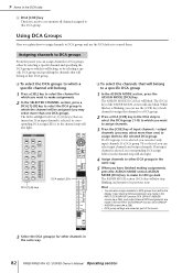
... one DCA group). Input channel DCA assignments are made in the INPUT DCA/GROUP function DCA GROUP ASSIGN screen (➥ p.296), and output channel DCA assignments are made in the OUTPUT DCA/GROUP function DCA GROUP ASSIGN screen (➥ p.258). • DCA group settings are turned on. Assigning channels to DCA groups From the panel, you may select more than one ) to assign channels. 3 Press the [CUE] key of the FADER MODE section will blink. The [DCA] key of input channels / output channels (you can select only input channels.
... one DCA group). Input channel DCA assignments are made in the INPUT DCA/GROUP function DCA GROUP ASSIGN screen (➥ p.296), and output channel DCA assignments are made in the OUTPUT DCA/GROUP function DCA GROUP ASSIGN screen (➥ p.258). • DCA group settings are turned on. Assigning channels to DCA groups From the panel, you may select more than one ) to assign channels. 3 Press the [CUE] key of the FADER MODE section will blink. The [DCA] key of input channels / output channels (you can select only input channels.
Owner's Manual
Page 86
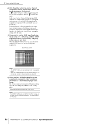
... the screen to turn it to a link group, click the SET BY CUE button for the corresponding link group in the DCA strip 2 Click the grid at the corresponding grid. To cancel the assignment, click the " " symbol once again. The EQ or compressor parameters of a channel belonging to the same compressor link group. 86 PM5D/PM5D-RH V2 / DSP5D Owner's Manual Operating section Note The STEREO LINK button and KEY IN SOURCE settings are...
... the screen to turn it to a link group, click the SET BY CUE button for the corresponding link group in the DCA strip 2 Click the grid at the corresponding grid. To cancel the assignment, click the " " symbol once again. The EQ or compressor parameters of a channel belonging to the same compressor link group. 86 PM5D/PM5D-RH V2 / DSP5D Owner's Manual Operating section Note The STEREO LINK button and KEY IN SOURCE settings are...

Owner's Manual
Page 87
... 010 Music #1 Scene memory HA library 00 Initial Data 10 HA #1 For each the PM5D and in the DSP5D. When you store a scene, the changes will be stored in the corresponding library, and the library number of the functions and screens listed below. • INPUT function settings • OUTPUT function settings • EFFECT PARAM screen settings • GEQ PARAM screen settings • SELECTIVE RECALL screen (SCENE function) settings • FADE TIME screen (SCENE function) settings • MIXER SETUP screen (SYS/W.CLOCK function) settings • HA screen (SYS/W.CLOCK function...
... 010 Music #1 Scene memory HA library 00 Initial Data 10 HA #1 For each the PM5D and in the DSP5D. When you store a scene, the changes will be stored in the corresponding library, and the library number of the functions and screens listed below. • INPUT function settings • OUTPUT function settings • EFFECT PARAM screen settings • GEQ PARAM screen settings • SELECTIVE RECALL screen (SCENE function) settings • FADE TIME screen (SCENE function) settings • MIXER SETUP screen (SYS/W.CLOCK function) settings • HA screen (SYS/W.CLOCK function...

Owner's Manual
Page 112
...-numbered MIX buses. By default, the L/R outputs of the signal sent from each channel to use a [SEL] key to select an input channel and turn the corresponding MIX encoder (➥ p.51). 112 PM5D/PM5D-RH V2 / DSP5D Owner's Manual Operating section Hint You can access the EFFECT ASSIGN screen (EFFECT function) to see all eight effect modules at the 100 (%) position, only the effect sound will send the output of the MIX section, then use an internal effect via a MIX bus...
...-numbered MIX buses. By default, the L/R outputs of the signal sent from each channel to use a [SEL] key to select an input channel and turn the corresponding MIX encoder (➥ p.51). 112 PM5D/PM5D-RH V2 / DSP5D Owner's Manual Operating section Hint You can access the EFFECT ASSIGN screen (EFFECT function) to see all eight effect modules at the 100 (%) position, only the effect sound will send the output of the MIX section, then use an internal effect via a MIX bus...

Owner's Manual
Page 124
... the LIBRARY NAME column of the currently selected line to specify the port number (1-8) as the program change transmission/reception mode, use the box at the right to open the MIDI PGM CHANGE window. 124 PM5D/PM5D-RH V2 / DSP5D Owner's Manual Operating section MIDI USB SLOT 1-4 The rear panel MIDI IN/OUT connectors The rear panel USB connector An I/O card installed in rear panel slot 1-4 Click the / buttons at the left and right of the...
... the LIBRARY NAME column of the currently selected line to specify the port number (1-8) as the program change transmission/reception mode, use the box at the right to open the MIDI PGM CHANGE window. 124 PM5D/PM5D-RH V2 / DSP5D Owner's Manual Operating section MIDI USB SLOT 1-4 The rear panel MIDI IN/OUT connectors The rear panel USB connector An I/O card installed in rear panel slot 1-4 Click the / buttons at the left and right of the...
Owner's Manual
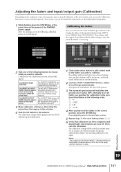
Page 161
... calibration settings will be shown for the calibration item you selected will appear, allowing you can also make fine adjustments to the analog input/output gain. 1 While holding down the [ENTER] key of the panel, turn off . CALIBRATE FADER POSITION The FADER CALIBRATION window will appear. Note The progress bar will begin automatically. Other functions 19 PM5D/PM5D-RH V2 / DSP5D Owner's Manual Operating section...
... calibration settings will be shown for the calibration item you selected will appear, allowing you can also make fine adjustments to the analog input/output gain. 1 While holding down the [ENTER] key of the panel, turn off . CALIBRATE FADER POSITION The FADER CALIBRATION window will appear. Note The progress bar will begin automatically. Other functions 19 PM5D/PM5D-RH V2 / DSP5D Owner's Manual Operating section...

Owner's Manual
Page 164
... the cursor and turn the [DATA] encoder to switch this directly. G FADING/TRACKING indicator This area shows the FADING indicator while fade time is being generated by the meters in the upper left and right of MIDI signals, the indicator will light if signals are received (in the SYS/W.CLOCK function MIXER SETUP screen the BUS SETUP setting STEREO B is set to light. You can also click the / buttons to change this area to...
... the cursor and turn the [DATA] encoder to switch this directly. G FADING/TRACKING indicator This area shows the FADING indicator while fade time is being generated by the meters in the upper left and right of MIDI signals, the indicator will light if signals are received (in the SYS/W.CLOCK function MIXER SETUP screen the BUS SETUP setting STEREO B is set to light. You can also click the / buttons to change this area to...

Owner's Manual
Page 195
... output when the fader of the selected channel reaches -∞ dB. • FADER TALLY A control signal will be output when the fader of variation will be used to each GPI OUT port. N TEST This button tests the operation of each GPI OUT port, and the fader mode (trigger detection method) of the FADER START screen (➥ p.196). Information shown in the X-axis (horizontal) and Y-axis (vertical) dimensions...
... output when the fader of the selected channel reaches -∞ dB. • FADER TALLY A control signal will be output when the fader of variation will be used to each GPI OUT port. N TEST This button tests the operation of each GPI OUT port, and the fader mode (trigger detection method) of the FADER START screen (➥ p.196). Information shown in the X-axis (horizontal) and Y-axis (vertical) dimensions...

Owner's Manual
Page 207
... you operate a fader, the name display will show the name of the INPUT channel strip and DCA strip. • NAME The indicators will show the names assigned to the input channels / DCA groups in the NAME screen (INPUT PATCH function). (➥ p.282) • PORT For input channels, the indicators will switch to indicating that value. Q R S Q INTERNAL CLOCK This indicates the year/month/day (DATE) and time (TIME) of the DSP5D's power supply. R BACKGROUND...
... you operate a fader, the name display will show the name of the INPUT channel strip and DCA strip. • NAME The indicators will show the names assigned to the input channels / DCA groups in the NAME screen (INPUT PATCH function). (➥ p.282) • PORT For input channels, the indicators will switch to indicating that value. Q R S Q INTERNAL CLOCK This indicates the year/month/day (DATE) and time (TIME) of the DSP5D's power supply. R BACKGROUND...

Owner's Manual
Page 259
... position. 4 A Mute group This area shows the mute group number. Currentlypatched grids are linked with the SCENE MEMORY [1]-[8] keys of the panel (if the MUTE MASTER button is automatically turned off when you turn on /off for channels assigned to the grid where the cursor is located is on, pressing the [CUE] key of the panel. Input functions Appendices PM5D/PM5D-RH V2 / DSP5D Owner's Manual Reference section 259 The number corresponding to the same mute group. Move...
... position. 4 A Mute group This area shows the mute group number. Currentlypatched grids are linked with the SCENE MEMORY [1]-[8] keys of the panel (if the MUTE MASTER button is automatically turned off when you turn on /off for channels assigned to the grid where the cursor is located is on, pressing the [CUE] key of the panel. Input functions Appendices PM5D/PM5D-RH V2 / DSP5D Owner's Manual Reference section 259 The number corresponding to the same mute group. Move...

Owner's Manual
Page 274
.... ALL EQ COMP DELAY FADER ON BAL INSERT TO MTRX DCA MUTE LCR WITHOUT MIX SEND/ WITH MIX SEND All parameters EQ function settings COMP function settings DELAY function settings Fader level CH [ON] key on/off . OUTPUT VIEW function CH JOB (Channel job) screen 4 In this screen you can copy the desired parameter(s) from the selected output channel into buffer memory. C BUFFERED CH (Channel in the pasted data. D EXECUTE When you click this button, the settings of channel (you can select...
.... ALL EQ COMP DELAY FADER ON BAL INSERT TO MTRX DCA MUTE LCR WITHOUT MIX SEND/ WITH MIX SEND All parameters EQ function settings COMP function settings DELAY function settings Fader level CH [ON] key on/off . OUTPUT VIEW function CH JOB (Channel job) screen 4 In this screen you can copy the desired parameter(s) from the selected output channel into buffer memory. C BUFFERED CH (Channel in the pasted data. D EXECUTE When you click this button, the settings of channel (you can select...

Owner's Manual
Page 380
... fader assigned to an appropriate volume? Turning a MIX encoder does not ❍ Is the MIX [ON] key turned on ? Sound is not input ❍ Is the optional I /O card is gritty ❍ Check that the dither function matches the word length of the recording device. (➥ p.229) Signal is delayed ❍ Check whether the delay setting for a channel that has no monitor output ❍ Could the CUE INTERRUPTION button be on -screen settings such as the insert...
... fader assigned to an appropriate volume? Turning a MIX encoder does not ❍ Is the MIX [ON] key turned on ? Sound is not input ❍ Is the optional I /O card is gritty ❍ Check that the dither function matches the word length of the recording device. (➥ p.229) Signal is delayed ❍ Check whether the delay setting for a channel that has no monitor output ❍ Could the CUE INTERRUPTION button be on -screen settings such as the insert...


