
Owners Manual
Page 3
...batterij op het moment dat u het apparaat ann het einde van de levensduur of gelieve dan contact op te nemen met de vertegenwoordiging van Yamaha in uw land. • For the removal of the battery at the moment of the disposal at the end of life please consult ... terminal which is found in all installation instructions. Udskiftning må kun ske med batteri af samme fabrikat og type. IMPORTANT: When connecting this manual, meets FCC requirements. Follow all installations. The wire which is coloured BLUE must be connected to accessories and/ or another product use of radio...
...batterij op het moment dat u het apparaat ann het einde van de levensduur of gelieve dan contact op te nemen met de vertegenwoordiging van Yamaha in uw land. • For the removal of the battery at the moment of the disposal at the end of life please consult ... terminal which is found in all installation instructions. Udskiftning må kun ske med batteri af samme fabrikat og type. IMPORTANT: When connecting this manual, meets FCC requirements. Follow all installations. The wire which is coloured BLUE must be connected to accessories and/ or another product use of radio...

Owners Manual
Page 4
.... Improper grounding can damage it should appear to be malfunctioning, discontinue use immediately and have the device inspected by qualified Yamaha service personnel. These precautions include, but are using the product for a long time, make sure to their maximum. Location •...the power cord or plug becomes frayed or damaged, or if there is printed on , trip over, or roll anything over . 4 DME64N/DME24N Owner's Manual (5)-1 1/2 If it . These precautions include, but are not using is easily accessible. The device contains no user-serviceable parts. CAUTION...
.... Improper grounding can damage it should appear to be malfunctioning, discontinue use immediately and have the device inspected by qualified Yamaha service personnel. These precautions include, but are using the product for a long time, make sure to their maximum. Location •...the power cord or plug becomes frayed or damaged, or if there is printed on , trip over, or roll anything over . 4 DME64N/DME24N Owner's Manual (5)-1 1/2 If it . These precautions include, but are not using is easily accessible. The device contains no user-serviceable parts. CAUTION...

Owners Manual
Page 5
...other trademarks are the property of their respective holders and are hereby acknowledged. (5)-1 2/2 DME64N/DME24N Owner's Manual 5 When the backup battery is a trademark of Ricoh Co., Ltd. • CobraNet and Peak Audio are for safely grounding the device and preventing electrical shock. Be sure to wait six...place heavy objects on or off the power immediately and unplug the power cord from rising too high. Consult qualifi ed Yamaha service personnel about replacing defective components. • The illustrations in backup battery. In particular, do not place the device on ...
...other trademarks are the property of their respective holders and are hereby acknowledged. (5)-1 2/2 DME64N/DME24N Owner's Manual 5 When the backup battery is a trademark of Ricoh Co., Ltd. • CobraNet and Peak Audio are for safely grounding the device and preventing electrical shock. Be sure to wait six...place heavy objects on or off the power immediately and unplug the power cord from rising too high. Consult qualifi ed Yamaha service personnel about replacing defective components. • The illustrations in backup battery. In particular, do not place the device on ...
Owners Manual
Page 6
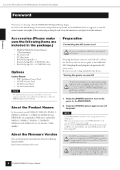
The Yamaha Pro Audio web site is at: http://www.yamahaproaudio.com/ 6 DME64N/DME24N Owner's Manual Foreword Foreword Thank you to read this owner's manual thoroughly before use, and keep it in a safe place for choosing a Yamaha DME64N/24N Digital Mixing Engine. In order to handle a wide range of the features and performance provided by the DME64N/24N, we urge...
The Yamaha Pro Audio web site is at: http://www.yamahaproaudio.com/ 6 DME64N/DME24N Owner's Manual Foreword Foreword Thank you to read this owner's manual thoroughly before use, and keep it in a safe place for choosing a Yamaha DME64N/24N Digital Mixing Engine. In order to handle a wide range of the features and performance provided by the DME64N/24N, we urge...

Owners Manual
Page 7
... 8 About the Firmware Version 8 Preparation 8 Connecting the AC power cord 8 Turning the power on and off 8 Introduction to the DME64N/24N 9 Differences between DME64N/24N 9 DME64N/24N Features 9 Audio System Network 9 Glossary for the DME64N/24N 9 Signal Types 11 System Examples 11 About DME Designer 13 The Controls and Connectors 14 Front Panel 14 Rear... Input/Output Characteristics 61 Control I/O 61 Connector Pin Assign 63 Dimensions 65 MIDI Data Format 66 Glossary 71 Panel Operation and Displays References Index 73 DME64N/DME24N Owner's Manual 7
... 8 About the Firmware Version 8 Preparation 8 Connecting the AC power cord 8 Turning the power on and off 8 Introduction to the DME64N/24N 9 Differences between DME64N/24N 9 DME64N/24N Features 9 Audio System Network 9 Glossary for the DME64N/24N 9 Signal Types 11 System Examples 11 About DME Designer 13 The Controls and Connectors 14 Front Panel 14 Rear... Input/Output Characteristics 61 Control I/O 61 Connector Pin Assign 63 Dimensions 65 MIDI Data Format 66 Glossary 71 Panel Operation and Displays References Index 73 DME64N/DME24N Owner's Manual 7
Owners Manual
Page 8
...;owing to the owner's manual that at the startup it is receiving data from generating a large noise spike or damaging your Control Panel, refer to the product all devices OFF before connecting or using the product for choosing a Yamaha DME64N/24N Digital Mixing Engine. ...Press the [POWER] switch again to unplug the power cord from the following order: audio sources, mixer (such as the DME Designer Owner's Manual. Accessories (Please make sure to turn off the...
...;owing to the owner's manual that at the startup it is receiving data from generating a large noise spike or damaging your Control Panel, refer to the product all devices OFF before connecting or using the product for choosing a Yamaha DME64N/24N Digital Mixing Engine. ...Press the [POWER] switch again to unplug the power cord from the following order: audio sources, mixer (such as the DME Designer Owner's Manual. Accessories (Please make sure to turn off the...

Owners Manual
Page 9
... are called an "area." Each configuration determines the audio function(s) of the DME24N. Refer to the DME Designer Owner's Manual for the DME64N/24N This section explains terminology specific to the DME64N/24N. The DME64N has approximately double the DSP processing power of the corresponding DME64N/24N unit. One DME64N/24N unit has a number of configurations, and...
... are called an "area." Each configuration determines the audio function(s) of the DME24N. Refer to the DME Designer Owner's Manual for the DME64N/24N This section explains terminology specific to the DME64N/24N. The DME64N has approximately double the DSP processing power of the corresponding DME64N/24N unit. One DME64N/24N unit has a number of configurations, and...

Owners Manual
Page 10
Up to the DME64N/24N 10 DME64N/DME24N Owner's Manual CLOCK 96kHz 88.2kHz 48kHz 44.1kHz 1234 5 6 78 NETWORK PEAK MID MASTER SIGNAL IN 1234 5 6 78 PEAK SIGNAL OUT SCENE NUMBER Scene 2 Introduction to 999 scenes can be stored for the DME64N/24N Scene A combination of... all configuration and preset parameters is called a "scene." Scenes can be recalled from an ICP1, GPI device, other external controllers, DME64N/DME24N, or computer. Scene structure Scene Scene 1 Scene 2 Matrix Mixer Configuration 16 x 8 Preset Parameter Ex.: Gate • Attack • ...
Up to the DME64N/24N 10 DME64N/DME24N Owner's Manual CLOCK 96kHz 88.2kHz 48kHz 44.1kHz 1234 5 6 78 NETWORK PEAK MID MASTER SIGNAL IN 1234 5 6 78 PEAK SIGNAL OUT SCENE NUMBER Scene 2 Introduction to 999 scenes can be stored for the DME64N/24N Scene A combination of... all configuration and preset parameters is called a "scene." Scenes can be recalled from an ICP1, GPI device, other external controllers, DME64N/DME24N, or computer. Scene structure Scene Scene 1 Scene 2 Matrix Mixer Configuration 16 x 8 Preset Parameter Ex.: Gate • Attack • ...

Owners Manual
Page 11
...DME64N/24N Signal Types Signal Types DME64N/24N audio...DME64N Word clock transmission and reception to and from other devices (depending on function of card). Number of I /O Slot) Audio...DME64N/24N Connector [USB] Connector [NETWORK] Connector [MIDI] Connector [GPI] Connector [CASCADE] Connector (DME64N only) [WORD CLOCK] Connector [REMOTE] Connector (Audio...Audio signal transmission and reception will be required to send and receive audio...as follows. 1 Audio The DME64N/24N will occur ...audio equipment. Control signals between MIDI controller and DME64N/ 24N. Reference Page 22 23 30 ...
...DME64N/24N Signal Types Signal Types DME64N/24N audio...DME64N Word clock transmission and reception to and from other devices (depending on function of card). Number of I /O Slot) Audio...DME64N/24N Connector [USB] Connector [NETWORK] Connector [MIDI] Connector [GPI] Connector [CASCADE] Connector (DME64N only) [WORD CLOCK] Connector [REMOTE] Connector (Audio...Audio signal transmission and reception will be required to send and receive audio...as follows. 1 Audio The DME64N/24N will occur ...audio equipment. Control signals between MIDI controller and DME64N/ 24N. Reference Page 22 23 30 ...
Owners Manual
Page 12
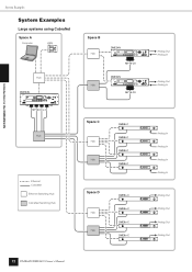
... In Analog In DME8o-C DME8o-C DME8o-C DME8o-C Analog Out Analog Out Analog Out Analog Out 12 DME64N/DME24N Owner's Manual Introduction to the DME64N/24N System Examples System Examples Large systems using CobraNet Space A Computer ICP1 Hub DME64N SCENE HOME UTILITY LEVEL MUTE CANCEL ENTER MY16-CII x 4 Hub Ethernet CobraNet Ethernet Switching Hub CobraNet...
... In Analog In DME8o-C DME8o-C DME8o-C DME8o-C Analog Out Analog Out Analog Out Analog Out 12 DME64N/DME24N Owner's Manual Introduction to the DME64N/24N System Examples System Examples Large systems using CobraNet Space A Computer ICP1 Hub DME64N SCENE HOME UTILITY LEVEL MUTE CANCEL ENTER MY16-CII x 4 Hub Ethernet CobraNet Ethernet Switching Hub CobraNet...
Owners Manual
Page 13
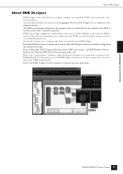
...you to build a configuration that are required for connection, refer to the "DME Setup Manual." DME64N/DME24N Owner's Manual 13 Please download the DME Designer application, driver, DME setup manual, and DME Designer Owner's Manual at the following URL: http://www.yamahaproaudio.com/ Refer to the "Connecting to a... Ethernet connection. For details on the computer monitor. Introduction to the DME64N/24N About DME Designer About DME Designer DME Designer software enables you can build the DME series audio system using graphic blocks in DME Designer that are transferred from the...
...you to build a configuration that are required for connection, refer to the "DME Setup Manual." DME64N/DME24N Owner's Manual 13 Please download the DME Designer application, driver, DME setup manual, and DME Designer Owner's Manual at the following URL: http://www.yamahaproaudio.com/ Refer to the "Connecting to a... Ethernet connection. For details on the computer monitor. Introduction to the DME64N/24N About DME Designer About DME Designer DME Designer software enables you can build the DME series audio system using graphic blocks in DME Designer that are transferred from the...

Owners Manual
Page 14
...flash red. If a problem occurs the indicator will light green. Refer to light in red. 14 DME64N/DME24N Owner's Manual When this happens the indicator corresponding to the frequency of the internal clock will light green, and all of these... indicators will temporarily be selected. The Controls and Connectors Front Panel The Controls and Connectors Front Panel DME64N 1 DME24N 1 ) 9 ^ & º¡ !@#$% SCENE HOME UTILITY LEVEL MUTE ...
...flash red. If a problem occurs the indicator will light green. Refer to light in red. 14 DME64N/DME24N Owner's Manual When this happens the indicator corresponding to the frequency of the internal clock will light green, and all of these... indicators will temporarily be selected. The Controls and Connectors Front Panel The Controls and Connectors Front Panel DME64N 1 DME24N 1 ) 9 ^ & º¡ !@#$% SCENE HOME UTILITY LEVEL MUTE ...

Owners Manual
Page 15
...selected parameters. & [E F] Buttons Move the display cursor in the corresponding directions. * [CANCEL] Button Closes the window on the corresponding built-in analog audio input or output ([IN] and [OUT] connectors) reaches or exceeds -3 dB. 8 [SIGNAL] Indicator (DME24N only) Light green when a signal ...group master (page 9). The indicator will appear. The indicator will light green when reception and transmission occur simultaneously. DME64N/DME24N Owner's Manual 15 The scene store display will light green while the scene recall or store display is occurring via the [MIDI...
...selected parameters. & [E F] Buttons Move the display cursor in the corresponding directions. * [CANCEL] Button Closes the window on the corresponding built-in analog audio input or output ([IN] and [OUT] connectors) reaches or exceeds -3 dB. 8 [SIGNAL] Indicator (DME24N only) Light green when a signal ...group master (page 9). The indicator will appear. The indicator will light green when reception and transmission occur simultaneously. DME64N/DME24N Owner's Manual 15 The scene store display will light green while the scene recall or store display is occurring via the [MIDI...

Owners Manual
Page 16
...signal "L" or "H" at the +V terminal is securely grounded to the unit's GPI (General Purpose Interface) interface for connection details. 16 DME64N/DME24N Owner's Manual Connecting the device to more than ground point can result in ground loops that has a ground screw, use the supplied plug adaptor. The ...connect the adaptor's ground lead to a confirmed ground point. Output channels each have a ground screw be sure to connect the DME64N/24N ground screw to the ground screw. Even when the power switch is turned off, electricity is the device's three-pronged AC power ...
...signal "L" or "H" at the +V terminal is securely grounded to the unit's GPI (General Purpose Interface) interface for connection details. 16 DME64N/DME24N Owner's Manual Connecting the device to more than ground point can result in ground loops that has a ground screw, use the supplied plug adaptor. The ...connect the adaptor's ground lead to a confirmed ground point. Output channels each have a ground screw be sure to connect the DME64N/24N ground screw to the ground screw. Even when the power switch is turned off, electricity is the device's three-pronged AC power ...

Owners Manual
Page 17
...One expansion card can also connect a Yamaha PM5D or DM2000 and control the internal head amps of the eight inputs and outputs uses three pins - The CASCADE connector transmits and receives control, audio, and word clock signals. DME64N/DME24N Owner's Manual 17 The Controls and Connectors Rear ...four I /O Card Installation" on page 30 for installation details. ) [CASCADE IN] [CASCADE OUT] Connectors (DME64N only) This 68-pin D-SUB connector can be plugged in here for analog audio input and output. See "MIDI Connection ([MIDI] Connectors)" on page 20 for connection details. 5 [WORD CLOCK...
...One expansion card can also connect a Yamaha PM5D or DM2000 and control the internal head amps of the eight inputs and outputs uses three pins - The CASCADE connector transmits and receives control, audio, and word clock signals. DME64N/DME24N Owner's Manual 17 The Controls and Connectors Rear ...four I /O Card Installation" on page 30 for installation details. ) [CASCADE IN] [CASCADE OUT] Connectors (DME64N only) This 68-pin D-SUB connector can be plugged in here for analog audio input and output. See "MIDI Connection ([MIDI] Connectors)" on page 20 for connection details. 5 [WORD CLOCK...

Owners Manual
Page 18
...Cover Mounting Security cover mounting screw holes (M3 size) are 423mm width and 96mm (DME64N) / 52mm (DME24N) height. Connect the AC power cord. Make sure the AC power to be replaced, contact your Yamaha dealer. Be sure to properly ground the device to prevent possible electrical shock. CAUTION Attaching...provided with the conditions marked on the front panel of about 20 millimeters between the front panel and the cover. 18 DME64N/DME24N Owner's Manual Preparation Setup Procedure Setup Setup Procedure Follow the steps outlined below to prepare the DME64N/24N for details.
...Cover Mounting Security cover mounting screw holes (M3 size) are 423mm width and 96mm (DME64N) / 52mm (DME24N) height. Connect the AC power cord. Make sure the AC power to be replaced, contact your Yamaha dealer. Be sure to properly ground the device to prevent possible electrical shock. CAUTION Attaching...provided with the conditions marked on the front panel of about 20 millimeters between the front panel and the cover. 18 DME64N/DME24N Owner's Manual Preparation Setup Procedure Setup Setup Procedure Follow the steps outlined below to prepare the DME64N/24N for details.
Owners Manual
Page 19
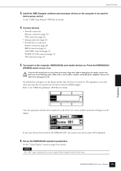
... data has been stored in the following order: audio sources, mixer and/or recorders, and finally power amplifiers. DME64N/DME24N Owner's Manual 19 Preparation Turn power to the "DME Setup Manual" (PDF file) for details. Press the DME64N/24N [POWER] switch to be displayed. 6. Set...connection(page 32) GPI connection (page 33) 5. NOTE The "NET" page settings must first be set up the DME64N/24N operation parameters. See the "DME Setup Manual" (PDF file) for the first time. Reverse this CAUTION order when turning power off. See the "Utility...
... data has been stored in the following order: audio sources, mixer and/or recorders, and finally power amplifiers. DME64N/DME24N Owner's Manual 19 Preparation Turn power to the "DME Setup Manual" (PDF file) for details. Press the DME64N/24N [POWER] switch to be displayed. 6. Set...connection(page 32) GPI connection (page 33) 5. NOTE The "NET" page settings must first be set up the DME64N/24N operation parameters. See the "DME Setup Manual" (PDF file) for the first time. Reverse this CAUTION order when turning power off. See the "Utility...

Owners Manual
Page 20
...DME64N/24N Owner's Manual." For the latest information on the upper surface of your DME64N is shown below, a hardware upgrade is charged for the hardware upgrade. If the serial number written on what cards can be used with the DME64N/24N, visit the Yamaha Pro Audio website at the end of the DME64N.../ Preparation 20 DME64N/DME24N Owner's Manual A fee is needed. I /O Cards As of April, 2007, Yamaha mini-YGDAI cards that can be used with the DME64N/24N are the third and fourth digits of the serial number. of audio input channels available on the DME64N/24N can be...
...DME64N/24N Owner's Manual." For the latest information on the upper surface of your DME64N is shown below, a hardware upgrade is charged for the hardware upgrade. If the serial number written on what cards can be used with the DME64N/24N, visit the Yamaha Pro Audio website at the end of the DME64N.../ Preparation 20 DME64N/DME24N Owner's Manual A fee is needed. I /O Cards As of April, 2007, Yamaha mini-YGDAI cards that can be used with the DME64N/24N are the third and fourth digits of the serial number. of audio input channels available on the DME64N/24N can be...

Owners Manual
Page 21
... remove the slot cover, as shown in the diagram, and push the card into the slot. Slide the I/O card into the slot so that the DME64N/24N power is OFF. If the power is on, turn it off. 2. NOTE The slot cover and screws will need to tighten the screws securely... in the guide rails, as shown in a safe place. 3. I/O Card Installation I /O card is later removed from the slot, so keep them in the diagram. CAUTION DME64N/DME24N Owner's Manual 21 Preparation
... remove the slot cover, as shown in the diagram, and push the card into the slot. Slide the I/O card into the slot so that the DME64N/24N power is OFF. If the power is on, turn it off. 2. NOTE The slot cover and screws will need to tighten the screws securely... in the guide rails, as shown in a safe place. 3. I/O Card Installation I /O card is later removed from the slot, so keep them in the diagram. CAUTION DME64N/DME24N Owner's Manual 21 Preparation
Owners Manual
Page 22
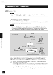
...to wait six seconds or more between connecting and disconnecting (or vice versa) the USB cable. 22 DME64N/DME24N Owner's Manual If the computer or DME64N/24N freezes, turn the power to the DME64N/24N off , and before connecting or disconnecting the USB cable, take the following two ways: (1)... Control the DME64N/24N from DME Designer. (2) Connect to the computer via USB, cancel the computer's energy saving ...
...to wait six seconds or more between connecting and disconnecting (or vice versa) the USB cable. 22 DME64N/DME24N Owner's Manual If the computer or DME64N/24N freezes, turn the power to the DME64N/24N off , and before connecting or disconnecting the USB cable, take the following two ways: (1)... Control the DME64N/24N from DME Designer. (2) Connect to the computer via USB, cancel the computer's energy saving ...


