
Owners Manual
Page 2
...an equilateral triangle is located on or pinched particularly at plugs, convenience receptacles, and the point where they exit from the apparatus. 11 Only use caution when moving the cart/ apparatus combination to qualified service personnel. The exclamation point within the product's enclosure that produce heat.... OR MOISTURE. The wide blade or the third prong are provided for replacement of time. 14 Refer all instructions. 5 Do not use this apparatus during lightning storms or when unused for long periods of the obsolete outlet. 10 Protect the power cord from being walked ...
...an equilateral triangle is located on or pinched particularly at plugs, convenience receptacles, and the point where they exit from the apparatus. 11 Only use caution when moving the cart/ apparatus combination to qualified service personnel. The exclamation point within the product's enclosure that produce heat.... OR MOISTURE. The wide blade or the third prong are provided for replacement of time. 14 Refer all instructions. 5 Do not use this apparatus during lightning storms or when unused for long periods of the obsolete outlet. 10 Protect the power cord from being walked ...

Owners Manual
Page 3
...See www.dtsc.ca.gov/hazardouswaste/perchlorate. • This applies only to products distributed by Yamaha-Kemble Music (U.K.) Ltd. (3 wires) • This applies only to products distributed by using one of this product in to those products distributed by the safety earth symbol or colored ...BROWN must be determined by turning the unit "OFF" and "ON", please try to use only high quality shielded cables. Failure to follow instructions could void your authority, granted by YAMAHA CORPORATION OF AMERICA. (class B) IMPORTANT NOTICE FOR THE UNITED KINGDOM Connecting the Plug and ...
...See www.dtsc.ca.gov/hazardouswaste/perchlorate. • This applies only to products distributed by Yamaha-Kemble Music (U.K.) Ltd. (3 wires) • This applies only to products distributed by using one of this product in to those products distributed by the safety earth symbol or colored ...BROWN must be determined by turning the unit "OFF" and "ON", please try to use only high quality shielded cables. Failure to follow instructions could void your authority, granted by YAMAHA CORPORATION OF AMERICA. (class B) IMPORTANT NOTICE FOR THE UNITED KINGDOM Connecting the Plug and ...

Owners Manual
Page 4
...;ed Yamaha service personnel. • If this manual in a car during electrical storms. • When removing the electric plug from the device or an outlet, always hold the plug itself and not the cord. The required voltage is printed on , trip over, or roll anything over . 4 DME64N/DME24N Owner...a safe place for a long time, make sure to their maximum. Pulling by qualified Yamaha service personnel. Water warning • Do not expose the device to rain, use of the device. • Use only the specified power cord. • Do not place the power cord near heat sources...
...;ed Yamaha service personnel. • If this manual in a car during electrical storms. • When removing the electric plug from the device or an outlet, always hold the plug itself and not the cord. The required voltage is printed on , trip over, or roll anything over . 4 DME64N/DME24N Owner...a safe place for a long time, make sure to their maximum. Pulling by qualified Yamaha service personnel. Water warning • Do not expose the device to rain, use of the device. • Use only the specified power cord. • Do not place the power cord near heat sources...

Owners Manual
Page 5
... equipment, mobile phone, or other electric devices. Consult qualifi ed Yamaha service personnel about replacing defective components. • The illustrations in this document are hereby acknowledged. (5)-1 2/2 DME64N/DME24N Owner's Manual 5 Handling caution • Do not insert your weight...Audio are trademarks of Cirrus Logic, Inc. • Ethernet is running low, the Display indicates "Low Battery" or "No Battery." Before turning the power on the buttons, switches or connectors. Then have been provided by qualified Yamaha service personnel. • Do not use...
... equipment, mobile phone, or other electric devices. Consult qualifi ed Yamaha service personnel about replacing defective components. • The illustrations in this document are hereby acknowledged. (5)-1 2/2 DME64N/DME24N Owner's Manual 5 Handling caution • Do not insert your weight...Audio are trademarks of Cirrus Logic, Inc. • Ethernet is running low, the Display indicates "Low Battery" or "No Battery." Before turning the power on the buttons, switches or connectors. Then have been provided by qualified Yamaha service personnel. • Do not use...
Owners Manual
Page 6
... applications - Foreword Foreword Thank you to read this owner's manual thoroughly before use, and keep it in a safe place for choosing a Yamaha DME64N/24N Digital Mixing Engine. The Yamaha Pro Audio web site is at: http://www.yamahaproaudio.com/ 6 DME64N/DME24N Owner's Manual institutional audio installations, sub-mixing, speaker system control, matrix and routing, multi-effect processing, and...
... applications - Foreword Foreword Thank you to read this owner's manual thoroughly before use, and keep it in a safe place for choosing a Yamaha DME64N/24N Digital Mixing Engine. The Yamaha Pro Audio web site is at: http://www.yamahaproaudio.com/ 6 DME64N/DME24N Owner's Manual institutional audio installations, sub-mixing, speaker system control, matrix and routing, multi-effect processing, and...
Owners Manual
Page 8
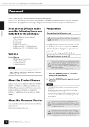
...Please make sure the following items are included in the package.) Foreword Foreword Thank you are all devices OFF before connecting or using the product for choosing a Yamaha DME64N/24N Digital Mixing Engine. About the Firmware Version You can set up with the Control Panel, as well as DME series,...more information on your speaker system, turn the devices on in the following order: audio sources, mixer (such as M7CL or PM5D), DME64N/24N, and finally power amplifiers. NOTE The DME64N/24N remembers scene settings when you turned off the power to turn all called the ...
...Please make sure the following items are included in the package.) Foreword Foreword Thank you are all devices OFF before connecting or using the product for choosing a Yamaha DME64N/24N Digital Mixing Engine. About the Firmware Version You can set up with the Control Panel, as well as DME series,...more information on your speaker system, turn the devices on in the following order: audio sources, mixer (such as M7CL or PM5D), DME64N/24N, and finally power amplifiers. NOTE The DME64N/24N remembers scene settings when you turned off the power to turn all called the ...

Owners Manual
Page 9
... the group master. DME64N/DME24N Owner's Manual 9 The DME24N can use the computer to basic mixing and matrix output functions, the DME64N/24N includes a equalizers, compressors, delay, etc. - Refer to the DME64N/24N. The DME64N has approximately double the DSP processing power of the corresponding DME64N/24N unit. Components and parameters The individual audio processing modules (equalizers...
... the group master. DME64N/DME24N Owner's Manual 9 The DME24N can use the computer to basic mixing and matrix output functions, the DME64N/24N includes a equalizers, compressors, delay, etc. - Refer to the DME64N/24N. The DME64N has approximately double the DSP processing power of the corresponding DME64N/24N unit. Components and parameters The individual audio processing modules (equalizers...

Owners Manual
Page 11
Introduction to the DME64N/24N Signal Types Signal Types DME64N/24N audio system signals can use the DME Designer application to control the entire device group, such as sending components to the devices and setting the parameters as required. 3 ...- Word clock transmission and reception to /from other DME series units as well as other DME series units You can be broadly categorized as follows. 1 Audio The DME64N/24N will occur primarily via the [REMOTE] connector. There are MIDI messages transferred between [USB] connectors, GPI signals transferred between [GPI] connectors, and...
Introduction to the DME64N/24N Signal Types Signal Types DME64N/24N audio system signals can use the DME Designer application to control the entire device group, such as sending components to the devices and setting the parameters as required. 3 ...- Word clock transmission and reception to /from other DME series units as well as other DME series units You can be broadly categorized as follows. 1 Audio The DME64N/24N will occur primarily via the [REMOTE] connector. There are MIDI messages transferred between [USB] connectors, GPI signals transferred between [GPI] connectors, and...
Owners Manual
Page 12
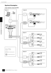
...ENGINE SATELLITE Analog In Analog In Analog In Analog In DME8o-C DME8o-C DME8o-C DME8o-C Analog Out Analog Out Analog Out Analog Out 12 DME64N/DME24N Owner's Manual CLOCK 96kHz 88.2kHz 48kHz 44.1kHz 1234 5 6 78 NETWORK MID PEAK MASTER SIGNAL IN 1234 5 6 78 ...PEAK SIGNAL OUT SCENE NUMBER MY16-CII Hub DME24N EXT. Introduction to the DME64N/24N System Examples System Examples Large systems using CobraNet Space A Computer ICP1 Hub DME64N SCENE HOME UTILITY LEVEL MUTE CANCEL ENTER MY16-CII x 4 Hub Ethernet CobraNet Ethernet Switching Hub CobraNet...
...ENGINE SATELLITE Analog In Analog In Analog In Analog In DME8o-C DME8o-C DME8o-C DME8o-C Analog Out Analog Out Analog Out Analog Out 12 DME64N/DME24N Owner's Manual CLOCK 96kHz 88.2kHz 48kHz 44.1kHz 1234 5 6 78 NETWORK MID PEAK MASTER SIGNAL IN 1234 5 6 78 ...PEAK SIGNAL OUT SCENE NUMBER MY16-CII Hub DME24N EXT. Introduction to the DME64N/24N System Examples System Examples Large systems using CobraNet Space A Computer ICP1 Hub DME64N SCENE HOME UTILITY LEVEL MUTE CANCEL ENTER MY16-CII x 4 Hub Ethernet CobraNet Ethernet Switching Hub CobraNet...
Owners Manual
Page 13
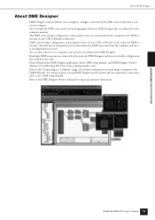
You can build the DME series audio system using graphic blocks in realtime from the computer and use it in DME Designer that includes those units. You can disconnect the DME series unit from DME Designer. For details on connecting a computer to the DME64N/24N. Refer to integrate, configure, ...configuration that are connected in the network, DME Designer enables you can also connect it to the "DME Setup Manual." Introduction to the DME64N/24N About DME Designer About DME Designer DME Designer software enables you to the DME Designer Owner's Manual for connection, refer to a ...
You can build the DME series audio system using graphic blocks in realtime from the computer and use it in DME Designer that includes those units. You can disconnect the DME series unit from DME Designer. For details on connecting a computer to the DME64N/24N. Refer to integrate, configure, ...configuration that are connected in the network, DME Designer enables you can also connect it to the "DME Setup Manual." Introduction to the DME64N/24N About DME Designer About DME Designer DME Designer software enables you to the DME Designer Owner's Manual for connection, refer to a ...

Owners Manual
Page 14
... in green, while transmitted data causes the indicator to the current word clock frequency will light green. Refer to be used, the USB-MIDI driver must be connected here when it is occurring via the [USB], [NETWORK], or [CASCADE]...; ™ £ 2 3 4 7 5 8 6 7 8 1 [USB] Connector A computer can be installed on the computer. The Controls and Connectors Front Panel The Controls and Connectors Front Panel DME64N 1 DME24N 1 ) 9 ^ & º¡ !@#$% SCENE HOME UTILITY LEVEL MUTE * CANCEL ( ENTER 2 4 5 3 6 ™ £ ) ^ 9 ! When a USB connection is ...
... in green, while transmitted data causes the indicator to the current word clock frequency will light green. Refer to be used, the USB-MIDI driver must be connected here when it is occurring via the [USB], [NETWORK], or [CASCADE]...; ™ £ 2 3 4 7 5 8 6 7 8 1 [USB] Connector A computer can be installed on the computer. The Controls and Connectors Front Panel The Controls and Connectors Front Panel DME64N 1 DME24N 1 ) 9 ^ & º¡ !@#$% SCENE HOME UTILITY LEVEL MUTE * CANCEL ( ENTER 2 4 5 3 6 ™ £ ) ^ 9 ! When a USB connection is ...

Owners Manual
Page 15
... will light red. 6 [MASTER] Indicator Lights green when the device is on. CAUTION When you are not using the product for a long time, make sure to light orange. NOTE The DME64N has no built-in this button is held for longer than 2 seconds (page 40). If this manual). #... exceeds -3 dB. 8 [SIGNAL] Indicator (DME24N only) Light green when a signal with a level greater than -40 dB is pressed to page 38 in analog audio inputs or outputs ([IN] and [OUT] connectors). 9 [SCENE NUMBER] Indicator Shows the current scene number. ) Display Displays scene information and device parameters. ! [...
... will light red. 6 [MASTER] Indicator Lights green when the device is on. CAUTION When you are not using the product for a long time, make sure to light orange. NOTE The DME64N has no built-in this button is held for longer than 2 seconds (page 40). If this manual). #... exceeds -3 dB. 8 [SIGNAL] Indicator (DME24N only) Light green when a signal with a level greater than -40 dB is pressed to page 38 in analog audio inputs or outputs ([IN] and [OUT] connectors). 9 [SCENE NUMBER] Indicator Shows the current scene number. ) Display Displays scene information and device parameters. ! [...

Owners Manual
Page 16
...threeprong type AC mains outlet. See "GPI Connection ([GPI] Connectors)" on page 18 for connection details. 16 DME64N/DME24N Owner's Manual NOTE When connecting to two-prong type AC mains outlets use the supplied AC plug adaptor and connect the adaptor's ground lead to and from 0V ~ 5V. either signal...to a confirmed ground point. Output channels each have a ground screw be sure to connect the DME64N/24N ground screw to only one ground point. Connecting the device to the AC mains using the product for transfer of control signals to the ground screw. Rear Panel Rear Panel...
...threeprong type AC mains outlet. See "GPI Connection ([GPI] Connectors)" on page 18 for connection details. 16 DME64N/DME24N Owner's Manual NOTE When connecting to two-prong type AC mains outlets use the supplied AC plug adaptor and connect the adaptor's ground lead to and from 0V ~ 5V. either signal...to a confirmed ground point. Output channels each have a ground screw be sure to connect the DME64N/24N ground screw to only one ground point. Connecting the device to the AC mains using the product for transfer of control signals to the ground screw. Rear Panel Rear Panel...

Owners Manual
Page 17
..." on page 23 for connection details. NOTE Use a STP (Shielded Twisted Pair) cable for this document). 6 [NETWORK] Connector This is a 100Base-TX/10Base-T Ethernet connector for connection to external equipment. The DME64N has four I /O Slots Optional Yamaha or third-party mini-YGDAI cards can deliver ... [MIDI OUT] [MIDI THRU] Connectors These are balanced Euroblock connectors for analog audio input and output. See "Ethernet Connection ([NETWORK] Connector)" on page 31 for connection details. Refer to Yamaha AD824 or AD8HR remote head amplifier or an RS-232C/RS-422 ...
..." on page 23 for connection details. NOTE Use a STP (Shielded Twisted Pair) cable for this document). 6 [NETWORK] Connector This is a 100Base-TX/10Base-T Ethernet connector for connection to external equipment. The DME64N has four I /O Slots Optional Yamaha or third-party mini-YGDAI cards can deliver ... [MIDI OUT] [MIDI THRU] Connectors These are balanced Euroblock connectors for analog audio input and output. See "Ethernet Connection ([NETWORK] Connector)" on page 31 for connection details. Refer to Yamaha AD824 or AD8HR remote head amplifier or an RS-232C/RS-422 ...

Owners Manual
Page 18
...the steps outlined below to prevent possible electrical shock. Use only the AC power cord supplied with the DME64N/24N. If the plug will not fit the outlet, have a proper outlet installed by the customer or contractor can be replaced, contact your Yamaha dealer. A security cover made by a quali&#... Owner's Manual Preparation Also, to "I /O cards. Do NOT modify the plug provided with the DME64N/24N. Yamaha cannot supply a security cover. The use a plug adapter which it is lost or damaged and needs to be provided for details. WARNING The type of AC power cord...
...the steps outlined below to prevent possible electrical shock. Use only the AC power cord supplied with the DME64N/24N. If the plug will not fit the outlet, have a proper outlet installed by the customer or contractor can be replaced, contact your Yamaha dealer. A security cover made by a quali&#... Owner's Manual Preparation Also, to "I /O cards. Do NOT modify the plug provided with the DME64N/24N. Yamaha cannot supply a security cover. The use a plug adapter which it is lost or damaged and needs to be provided for details. WARNING The type of AC power cord...
Owners Manual
Page 19
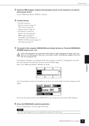
Install the DME Designer software and necessary drivers on the computer to the computer, DME64N/24N, and related devices on the display: If any scene data has been stored in the following order: audio sources, mixer and/or recorders, and finally power amplifiers. Reverse this ...64257;rst time. NOTE The "NET" page settings must first be used for details. No information will be set up the DME64N/24N operation parameters. See the "DME Setup Manual" (PDF file) for details. Press the DME64N/24N [POWER] switch to the "DME Setup Manual" (PDF file...
Install the DME Designer software and necessary drivers on the computer to the computer, DME64N/24N, and related devices on the display: If any scene data has been stored in the following order: audio sources, mixer and/or recorders, and finally power amplifiers. Reverse this ...64257;rst time. NOTE The "NET" page settings must first be used for details. No information will be set up the DME64N/24N operation parameters. See the "DME Setup Manual" (PDF file) for details. Press the DME64N/24N [POWER] switch to the "DME Setup Manual" (PDF file...

Owners Manual
Page 20
...one I /O Card Installation 7. For details, contact Yamaha customer support using the contact information located at : http://www.yamahaproaudio.com/ Preparation 20 DME64N/DME24N Owner's Manual For the latest information on what cards can be used with the DME64N/24N are as follows: Card Name MY8-AT MY8... of April, 2007, Yamaha mini-YGDAI cards that can be increased by plugging the appropriate mini-YGDAI I /O Cards As of the serial number. DME Designer setup, operation, and data transfer instructions can be used with the DME64N/24N, visit the Yamaha Pro Audio website at the end ...
...one I /O Card Installation 7. For details, contact Yamaha customer support using the contact information located at : http://www.yamahaproaudio.com/ Preparation 20 DME64N/DME24N Owner's Manual For the latest information on what cards can be used with the DME64N/24N are as follows: Card Name MY8-AT MY8... of April, 2007, Yamaha mini-YGDAI cards that can be increased by plugging the appropriate mini-YGDAI I /O Cards As of the serial number. DME Designer setup, operation, and data transfer instructions can be used with the DME64N/24N, visit the Yamaha Pro Audio website at the end ...
Owners Manual
Page 22
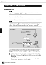
... Connection NOTE • Refer to be received/transmitted and the scene parameters can be set up using a DME64N/24N together with a computer. NOTE • When using DME Designer. • The USB port being used in damages or loss of data. The computer on which DME Designer is NOT transferring any data...(PDF file) for use by mode). USB connections can be used by DME Designer is not available for details on installing USB-MIDI Driver and DME Designer. • Make sure that the USB-MIDI Driver's THRU setting is "OFF." Make sure that DME64N/24N unit by transmitting MIDI...
... Connection NOTE • Refer to be received/transmitted and the scene parameters can be set up using a DME64N/24N together with a computer. NOTE • When using DME Designer. • The USB port being used in damages or loss of data. The computer on which DME Designer is NOT transferring any data...(PDF file) for use by mode). USB connections can be used by DME Designer is not available for details on installing USB-MIDI Driver and DME Designer. • Make sure that the USB-MIDI Driver's THRU setting is "OFF." Make sure that DME64N/24N unit by transmitting MIDI...
Owners Manual
Page 23
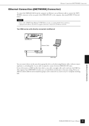
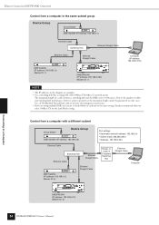
... then install DME-N Network Driver. If one of the DME64N/24N to an Ethernet network. Devices in the same device group directly to each other using Ethernet cables, without connecting them to connect between DME64N/24N units. Ethernet Connection ([NETWORK] Connector) Ethernet Connection ...([NETWORK] Connector) To control the DME64N/24N from the computer via a router or layer-3 compliant...
... then install DME-N Network Driver. If one of the DME64N/24N to an Ethernet network. Devices in the same device group directly to each other using Ethernet cables, without connecting them to connect between DME64N/24N units. Ethernet Connection ([NETWORK] Connector) Ethernet Connection ...([NETWORK] Connector) To control the DME64N/24N from the computer via a router or layer-3 compliant...
Owners Manual
Page 24
... Yamaha recommends that is 100 meters. The maximum length of cables and switching hub performance, however, proper operation at the maximum length cannot be guaranteed in the diagram are using multiple DME series units, set Link Mode on each unit to a Computer 24 DME64N/DME24N Owner's Manual Use ...a STP (Shielded Twisted Pair) cable to prevent electromagnetic interference. • If you are examples. • Use a switching hub that you select 100Base-TX for the Link Mode setting. ...
... Yamaha recommends that is 100 meters. The maximum length of cables and switching hub performance, however, proper operation at the maximum length cannot be guaranteed in the diagram are using multiple DME series units, set Link Mode on each unit to a Computer 24 DME64N/DME24N Owner's Manual Use ...a STP (Shielded Twisted Pair) cable to prevent electromagnetic interference. • If you are examples. • Use a switching hub that you select 100Base-TX for the Link Mode setting. ...


