Owners Manual
Page 13
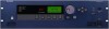
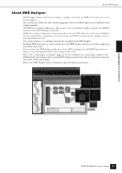
...from DME Designer. If multiple DME series units are displayed on connecting a computer to a computer and control it to the DME64N/24N. Please download the DME Designer application, driver, DME setup manual, and DME Designer Owner's Manual at the following URL: http://www.yamahaproaudio.com/ Refer to the "Connecting... connected DME series unit. You can also connect it in the network, DME Designer enables you can build the DME series audio system using graphic blocks in DME Designer that are connected in realtime from the computer and use it as an independent processor.
...from DME Designer. If multiple DME series units are displayed on connecting a computer to a computer and control it to the DME64N/24N. Please download the DME Designer application, driver, DME setup manual, and DME Designer Owner's Manual at the following URL: http://www.yamahaproaudio.com/ Refer to the "Connecting... connected DME series unit. You can also connect it in the network, DME Designer enables you can build the DME series audio system using graphic blocks in DME Designer that are connected in realtime from the computer and use it as an independent processor.

Owners Manual
Page 14
... will light green. Received data causes the indicator to light in green, while transmitted data causes the indicator to be used, the USB-MIDI driver must be connected here when it is occurring via the [USB], [NETWORK], or [CASCADE] connector. CLOCK] Indicator When a clock signal from... is detected with the master clock is detected all other indicators will light green. When a USB connection is to light in red. 14 DME64N/DME24N Owner's Manual Refer to flash red. 4 [NETWORK] Indicator Lights while data communication is necessary to the current word clock frequency...
... will light green. Received data causes the indicator to light in green, while transmitted data causes the indicator to be used, the USB-MIDI driver must be connected here when it is occurring via the [USB], [NETWORK], or [CASCADE] connector. CLOCK] Indicator When a clock signal from... is detected with the master clock is detected all other indicators will light green. When a USB connection is to light in red. 14 DME64N/DME24N Owner's Manual Refer to flash red. 4 [NETWORK] Indicator Lights while data communication is necessary to the current word clock frequency...
Owners Manual
Page 19
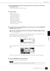
...The appropriate scene and other data must be used for details. Refer to be set up the DME64N/24N operation parameters. Setup Procedure 3. Install the DME Designer software and necessary drivers on . DME64N/DME24N Owner's Manual 19 Preparation See the "DME Setup Manual" (PDF file) for details...from the DME Designer. To prevent the initial power-on the display: If any scene data has been stored in the following order: audio sources, mixer and/or recorders, and finally power amplifiers. Connect devices. • Network connection Ethernet connection (page 23...
...The appropriate scene and other data must be used for details. Refer to be set up the DME64N/24N operation parameters. Setup Procedure 3. Install the DME Designer software and necessary drivers on . DME64N/DME24N Owner's Manual 19 Preparation See the "DME Setup Manual" (PDF file) for details...from the DME Designer. To prevent the initial power-on the display: If any scene data has been stored in the following order: audio sources, mixer and/or recorders, and finally power amplifiers. Connect devices. • Network connection Ethernet connection (page 23...
Owners Manual
Page 22
... or other application. Otherwise, the computer and/or DME64N/24N may freeze, resulting in the following actions: - Make sure that the DME64N/24N is NOT transferring any individual DME64N/24N and control that the USB-MIDI Driver's THRU setting is not available for details on installing... USB-MIDI Driver and DME Designer. • Make sure that DME64N/24N unit by transmitting MIDI commands from...
... or other application. Otherwise, the computer and/or DME64N/24N may freeze, resulting in the following actions: - Make sure that the DME64N/24N is NOT transferring any individual DME64N/24N and control that the USB-MIDI Driver's THRU setting is not available for details on installing... USB-MIDI Driver and DME Designer. • Make sure that DME64N/24N unit by transmitting MIDI commands from...
Owners Manual
Page 23
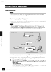
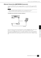
... devices in different subnet (different network address) groups can be assigned to all devices connected to the computer, then install DME-N Network Driver. A cross cable is a DME Satellite then either a cross cable or straight cable can be connected via Ethernet, use an Ethernet ... Connection ([NETWORK] Connector) Ethernet Connection ([NETWORK] Connector) To control the DME64N/24N from the computer via a router or layer-3 compliant switching hub. In this case, set Link Mode on installing DME-N Network Driver. • Appropriate IP addresses must first be used since the DME...
... devices in different subnet (different network address) groups can be assigned to all devices connected to the computer, then install DME-N Network Driver. A cross cable is a DME Satellite then either a cross cable or straight cable can be connected via Ethernet, use an Ethernet ... Connection ([NETWORK] Connector) Ethernet Connection ([NETWORK] Connector) To control the DME64N/24N from the computer via a router or layer-3 compliant switching hub. In this case, set Link Mode on installing DME-N Network Driver. • Appropriate IP addresses must first be used since the DME...
Owners Manual
Page 61
... cables connected correctly? • Has the USB-MIDI driver been properly installed? • If you are using the [NETWORK] connector, has the DME-N Network Driver been properly set up? • Has MIDI Setup been...8226; Is power to select a scene that does not output audio? • Are you have forgotten your password contact your Yamaha service center or representative. Use Defined Button settings change... lock function (page 38) to prevent unwanted operation of the panel controls on specific DME64N/24N or ICP1 units. • Use the DME Designer to make sure that multiple User ...
... cables connected correctly? • Has the USB-MIDI driver been properly installed? • If you are using the [NETWORK] connector, has the DME-N Network Driver been properly set up? • Has MIDI Setup been...8226; Is power to select a scene that does not output audio? • Are you have forgotten your password contact your Yamaha service center or representative. Use Defined Button settings change... lock function (page 38) to prevent unwanted operation of the panel controls on specific DME64N/24N or ICP1 units. • Use the DME Designer to make sure that multiple User ...

Owners Manual
Page 75
...[48kHz] [44.1kHz] Indicator 14 A [AC IN] Connector 16 ADAT (Alesis Digital Audio Tape) (Glossary 70 AES/EBU (Audio Engineering Society/European Broadcasting Union) (Glossary 70 area 9 audio 11 B Band Output Level 40 Battery 45 BNC (Bayonet Nut Connector, or Bayonet Neill ...Dial 15 dimensions 64 Disp Page 46 Display 15 Display Setup (Disp) Page 46 DME Designer 13 DME-N Network Driver 23 DSP (Digital Signal processor) (Glossary 70 D-Sub (Glossary 70 E [ENTER] Button 15 Error Messages 56...pass Filter Frequency 53 [HOME] Button 15 Host 50 HPF 53 DME64N/DME24N Owner's Manual 75
...[48kHz] [44.1kHz] Indicator 14 A [AC IN] Connector 16 ADAT (Alesis Digital Audio Tape) (Glossary 70 AES/EBU (Audio Engineering Society/European Broadcasting Union) (Glossary 70 area 9 audio 11 B Band Output Level 40 Battery 45 BNC (Bayonet Nut Connector, or Bayonet Neill ...Dial 15 dimensions 64 Disp Page 46 Display 15 Display Setup (Disp) Page 46 DME Designer 13 DME-N Network Driver 23 DSP (Digital Signal processor) (Glossary 70 D-Sub (Glossary 70 E [ENTER] Button 15 Error Messages 56...pass Filter Frequency 53 [HOME] Button 15 Host 50 HPF 53 DME64N/DME24N Owner's Manual 75

Owners Manual
Page 77
... (Tascam Digital Interface Format) (Glossary 71 troubleshooting 58 U Unit No 54 USB (Universal Serial Bus) (Glossary 71 USB Connection 22 [USB] Connector 14 USB-MIDI Driver 22 User Defined button 9 User Defined Button (Edit 37 User Defined Button Names 34 User Defined buttons (User Defined parameters 9 User Defined Lock 47 Utility... 31 [WORD CLOCK IN] [WORD CLOCK OUT] Connectors 17, 31 word clock master 31 Word Clock Setup (WCLK) Page 49 word clock slave 31 Z zones 9 DME64N/DME24N Owner's Manual 77
... (Tascam Digital Interface Format) (Glossary 71 troubleshooting 58 U Unit No 54 USB (Universal Serial Bus) (Glossary 71 USB Connection 22 [USB] Connector 14 USB-MIDI Driver 22 User Defined button 9 User Defined Button (Edit 37 User Defined Button Names 34 User Defined buttons (User Defined parameters 9 User Defined Lock 47 Utility... 31 [WORD CLOCK IN] [WORD CLOCK OUT] Connectors 17, 31 word clock master 31 Word Clock Setup (WCLK) Page 49 word clock slave 31 Z zones 9 DME64N/DME24N Owner's Manual 77