
Owners Manual
Page 7
... 9 Differences between DME64N/24N 9 DME64N/24N Features 9 Audio System Network 9 Glossary for the DME64N/24N 9 Signal Types 11 System Examples 11 About DME Designer 13 The Controls and Connectors 14 Front Panel 14 Rear Panel 16 Setup 18 Setup Procedure 18 I/O Card Installation 20 Compatible I/O Cards 20 I/O Card Installation Procedure 21 Connecting to a Computer 22 USB Connection...
... 9 Differences between DME64N/24N 9 DME64N/24N Features 9 Audio System Network 9 Glossary for the DME64N/24N 9 Signal Types 11 System Examples 11 About DME Designer 13 The Controls and Connectors 14 Front Panel 14 Rear Panel 16 Setup 18 Setup Procedure 18 I/O Card Installation 20 Compatible I/O Cards 20 I/O Card Installation Procedure 21 Connecting to a Computer 22 USB Connection...

Owners Manual
Page 9
... a number of the DME24N. User Defined buttons Assigning parameters to be patched together via DME Designer to 24 audio I/O channels. Introduction to the DME64N/24N Differences between DME64N/24N The DME64N has four I/O card slots, while the DME24N has one DME series unit that functions as the "group master" and controls all other...
... a number of the DME24N. User Defined buttons Assigning parameters to be patched together via DME Designer to 24 audio I/O channels. Introduction to the DME64N/24N Differences between DME64N/24N The DME64N has four I/O card slots, while the DME24N has one DME series unit that functions as the "group master" and controls all other...

Owners Manual
Page 11
...DME64N only) [WORD CLOCK] Connector [REMOTE] Connector (Audio I/O Connectors) (DME24N only) (I /O Serial signal transmission/reception channels depends (depending on function of input/output. • Control signals between computer and - Control signals (MIDI commands) - Number of I /O Slot) Audio Signal Device Control Word Clock - - - - 32 channels of card... to and from other DME series units as well as other audio equipment. Introduction to the DME64N/24N Signal Types Signal Types DME64N/24N audio system signals can use the DME Designer application to control the entire...
...DME64N only) [WORD CLOCK] Connector [REMOTE] Connector (Audio I/O Connectors) (DME24N only) (I /O Serial signal transmission/reception channels depends (depending on function of input/output. • Control signals between computer and - Control signals (MIDI commands) - Number of I /O Slot) Audio Signal Device Control Word Clock - - - - 32 channels of card... to and from other DME series units as well as other audio equipment. Introduction to the DME64N/24N Signal Types Signal Types DME64N/24N audio system signals can use the DME Designer application to control the entire...

Owners Manual
Page 17
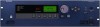
... details. Refer to the appropriate inputs and outputs. 9 I/O Slots Optional Yamaha or third-party mini-YGDAI cards can be plugged in here for analog audio input and output. The DME64N has four I /O Card Installation" on page 31 for connection details. One expansion card can also connect a Yamaha PM5D or DM2000 and control the internal head amps of...
... details. Refer to the appropriate inputs and outputs. 9 I/O Slots Optional Yamaha or third-party mini-YGDAI cards can be plugged in here for analog audio input and output. The DME64N has four I /O Card Installation" on page 31 for connection details. One expansion card can also connect a Yamaha PM5D or DM2000 and control the internal head amps of...

Owners Manual
Page 18
... outlet. Setup Procedure Setup Setup Procedure Follow the steps outlined below to prepare the DME64N/24N for grounding purposes). Connect the AC power cord. See "Dimensions" on page 20 for details. Yamaha cannot supply a security cover. Install any required I /O Card Installation" on page 67 for details. 2. If the plug will not fit the...
... outlet. Setup Procedure Setup Setup Procedure Follow the steps outlined below to prepare the DME64N/24N for grounding purposes). Connect the AC power cord. See "Dimensions" on page 20 for details. Yamaha cannot supply a security cover. Install any required I /O Card Installation" on page 67 for details. 2. If the plug will not fit the...

Owners Manual
Page 20
... the end of April, 2007, Yamaha mini-YGDAI cards that can be used with the DME64N/24N, visit the Yamaha Pro Audio website at: http://www.yamahaproaudio.com/ Preparation 20 DME64N/DME24N Owner's Manual I/O Card Installation The DME64N has four I/O card slots, and the DME24N has one I /O Card Installation 7. Compatible I /O card(s) into the available card slot(s). of Available Cards DME64N DME24N 4 1 4 1 4 1 4 1 4 1 4 1 4 1 4 1 4 1 4 1 4 1 4 1 4 1 4 1 4 1 4 1 4(*) 1 4 1 The input/output numbers...
... the end of April, 2007, Yamaha mini-YGDAI cards that can be used with the DME64N/24N, visit the Yamaha Pro Audio website at: http://www.yamahaproaudio.com/ Preparation 20 DME64N/DME24N Owner's Manual I/O Card Installation The DME64N has four I/O card slots, and the DME24N has one I /O Card Installation 7. Compatible I /O card(s) into the available card slot(s). of Available Cards DME64N DME24N 4 1 4 1 4 1 4 1 4 1 4 1 4 1 4 1 4 1 4 1 4 1 4 1 4 1 4 1 4 1 4 1 4(*) 1 4 1 The input/output numbers...

Owners Manual
Page 21
...and remove the slot cover, as shown in the diagram, and push the card into the slot so that the DME64N/24N power is OFF. Guide Rail 4. CAUTION DME64N/DME24N Owner's Manual 21 Preparation Be sure to push the card all the way back into the slot. If the screws are left loose ...proper contact may result. If the power is later removed from the slot, so keep them in the diagram. I/O Card Installation I /O card is on, turn it...
...and remove the slot cover, as shown in the diagram, and push the card into the slot so that the DME64N/24N power is OFF. Guide Rail 4. CAUTION DME64N/DME24N Owner's Manual 21 Preparation Be sure to push the card all the way back into the slot. If the screws are left loose ...proper contact may result. If the power is later removed from the slot, so keep them in the diagram. I/O Card Installation I /O card is on, turn it...

Owners Manual
Page 27
... clock transmission and reception functionality. DME64N/DME24N Owner's Manual 27 Audio I /O card slot. Plug the Euroblock plug into the available card slot(s). For details on the DME64N/24N can be increased by plugging the appropriate mini-YGDAI I /O card Installation Procedure" (page 21). 5. Refer to "I /O card(s) into the panel connector. Some types of audio input channels available on how...
... clock transmission and reception functionality. DME64N/DME24N Owner's Manual 27 Audio I /O card slot. Plug the Euroblock plug into the available card slot(s). For details on the DME64N/24N can be increased by plugging the appropriate mini-YGDAI I /O card Installation Procedure" (page 21). 5. Refer to "I /O card(s) into the panel connector. Some types of audio input channels available on how...
Owners Manual
Page 31
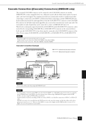
... together with the DME Satellite, you can be connected to a mixer or DME64N/24N unit is from the PM5D via CobraNet connections to MY16-C or MY16-CII cards. Connecting to [CASCADE OUT]. In the unidirectional mode the audio signal flow is 32. NOTE It is version 3.07 or higher, you must assign...
... together with the DME Satellite, you can be connected to a mixer or DME64N/24N unit is from the PM5D via CobraNet connections to MY16-C or MY16-CII cards. Connecting to [CASCADE OUT]. In the unidirectional mode the audio signal flow is 32. NOTE It is version 3.07 or higher, you must assign...

Owners Manual
Page 32
The word clock signal from an external device can be received and transmitted via a mini-YGDAI card installed in an I/O slot, or the [CASCADE IN] and [CASCADE OUT] connectors. NOTE A device transmitting the word clock signal that will use the internal word ... OUT (BNC) Master Word Clock Distribution Box WC IN (BNC) WC IN (BNC) WC IN (BNC) WC IN (BNC) DME64N/24N Word Clock Slave DME64N/24N Word Clock Slave DME64N/24N Word Clock Slave DME64N/24N Word Clock Slave Daisy Chain Connection NOTE This method is the "word clock master," while devices received the...
The word clock signal from an external device can be received and transmitted via a mini-YGDAI card installed in an I/O slot, or the [CASCADE IN] and [CASCADE OUT] connectors. NOTE A device transmitting the word clock signal that will use the internal word ... OUT (BNC) Master Word Clock Distribution Box WC IN (BNC) WC IN (BNC) WC IN (BNC) WC IN (BNC) DME64N/24N Word Clock Slave DME64N/24N Word Clock Slave DME64N/24N Word Clock Slave DME64N/24N Word Clock Slave Daisy Chain Connection NOTE This method is the "word clock master," while devices received the...

Owners Manual
Page 44
...on/off . Current status and setup whether an event schedule setup in a DME64N/24N I/O slot. Displays info about an I /O card slots. Displays the audio format - 88.2 or 96 kHz. Current status and setup for the DME64N/24N's power-on /off . Sets the minimum calibration value. Current status and... of the word clock received at the [WORD CLOCK IN] connector. Resets the installed card. Current status and setup for the Utility display settings. Utility Displays Utility Displays Most basic DME64N/24N functions can be executed or not. Current status and setup for connected MIDI devices...
...on/off . Current status and setup whether an event schedule setup in a DME64N/24N I/O slot. Displays info about an I /O card slots. Displays the audio format - 88.2 or 96 kHz. Current status and setup for the DME64N/24N's power-on /off . Sets the minimum calibration value. Current status and... of the word clock received at the [WORD CLOCK IN] connector. Resets the installed card. Current status and setup for the Utility display settings. Utility Displays Utility Displays Most basic DME64N/24N functions can be executed or not. Current status and setup for connected MIDI devices...

Owners Manual
Page 50
...] connectors. 5 SLOT1~4 Shows the status of DME64N/DME24N units from external MIDI controllers via I/O cards installed in sync with the master word clock. Word Clock Setup (WCLK) Page Shows the status of incoming word clock signals, and allows setup of the word clock signal at the Yamaha Pro Audio website (http:// www.yamahaproaudio.com/). and...
...] connectors. 5 SLOT1~4 Shows the status of DME64N/DME24N units from external MIDI controllers via I/O cards installed in sync with the master word clock. Word Clock Setup (WCLK) Page Shows the status of incoming word clock signals, and allows setup of the word clock signal at the Yamaha Pro Audio website (http:// www.yamahaproaudio.com/). and...

Owners Manual
Page 51
... the output setting is currently selected for MIDI input. The number of audio channels that can also be connected. SLOT-1, SLOT-2, SLOT-3, SLOT-4: A card installed in an I /O slot is on page 38. Panel Operation and Displays DME64N/DME24N Owner's Manual 51 SP (Double Speed): An 88.2/96 kHz... DME Designer will not be connected. CH (Double Channel): A 44.1/48 kHz card is installed, and 88.2 or 96 kHz audio is half the number of the card installed in the corresponding I /O card slot. Some cards can be handled in this setting when a general-purpose Logic or Cubase controller (...
... the output setting is currently selected for MIDI input. The number of audio channels that can also be connected. SLOT-1, SLOT-2, SLOT-3, SLOT-4: A card installed in an I /O slot is on page 38. Panel Operation and Displays DME64N/DME24N Owner's Manual 51 SP (Double Speed): An 88.2/96 kHz... DME Designer will not be connected. CH (Double Channel): A 44.1/48 kHz card is installed, and 88.2 or 96 kHz audio is half the number of the card installed in the corresponding I /O card slot. Some cards can be handled in this setting when a general-purpose Logic or Cubase controller (...

Owners Manual
Page 54
...3 5 2 1 HA Specifies the type of the AD8HR. Edit using two 44.1/48 kHz channels to transfer each audio channel of the AD8HR. INT96K: Sets the 96 kHz internal word clock as the master clock of the AD824. 3 Format (AD8HR... signal input via I /O slots as the master clock of the AD824. Panel Operation and Displays 54 DME64N/DME24N Owner's Manual Available settings of the AD824 are "D OUT A," "WCLK IN," "INT44.1K," .... When the AD8HR and AD824 are AD8HR, AD824, and Built-in the I /O cards installed in HA (DME24N only). BNC: Sets the word clock signal at BNC connector as...
...3 5 2 1 HA Specifies the type of the AD8HR. Edit using two 44.1/48 kHz channels to transfer each audio channel of the AD8HR. INT96K: Sets the 96 kHz internal word clock as the master clock of the AD824. 3 Format (AD8HR... signal input via I /O slots as the master clock of the AD824. Panel Operation and Displays 54 DME64N/DME24N Owner's Manual Available settings of the AD824 are "D OUT A," "WCLK IN," "INT44.1K," .... When the AD8HR and AD824 are AD8HR, AD824, and Built-in the I /O cards installed in HA (DME24N only). BNC: Sets the word clock signal at BNC connector as...

Owners Manual
Page 56
... used in the current scene. The meter does not operate during a connection check. When input-only or output-only cards like AD or DA cards are directly connected on the ICP1 display. 56 DME64N/DME24N Owner's Manual Panel Operation and Displays In the DME24N, the internal AD and internal DA are inserted in..., you cannot perform checks in this mode. MODE: Summing Sums all input signals coming from Inputs (-12dB), without using DME Designer by directly connecting the DME64N/24N input/output.
... used in the current scene. The meter does not operate during a connection check. When input-only or output-only cards like AD or DA cards are directly connected on the ICP1 display. 56 DME64N/DME24N Owner's Manual Panel Operation and Displays In the DME24N, the internal AD and internal DA are inserted in..., you cannot perform checks in this mode. MODE: Summing Sums all input signals coming from Inputs (-12dB), without using DME Designer by directly connecting the DME64N/24N input/output.
Owners Manual
Page 58
...PM5D, turn off the CONNECT button in sync with the clock Make sure that the DME64N/24N and the card or signal being received at the [CASCADE OUT] connector. This cannot be lost . The DME64N/24N clock is already selected for battery replacement. Communication with the master DME device ... and contact a Yamaha dealer for internal head amp control from the external device. Set the MIDI Port parameter to something other than hubs, routers, and related devices are set , since the Event Log saving area is properly connected, and that the DME64N/24N and the card or external source ...
...PM5D, turn off the CONNECT button in sync with the clock Make sure that the DME64N/24N and the card or signal being received at the [CASCADE OUT] connector. This cannot be lost . The DME64N/24N clock is already selected for battery replacement. Communication with the master DME device ... and contact a Yamaha dealer for internal head amp control from the external device. Set the MIDI Port parameter to something other than hubs, routers, and related devices are set , since the Event Log saving area is properly connected, and that the DME64N/24N and the card or external source ...

Owners Manual
Page 59
...during which the computer manipulates scene data. Refer this problem to a contact a Yamaha dealer. Refer this problem to a Yamaha dealer. The DME64N clock is no duplicates. Make sure that the DME64N and the card or external source supplying the word clock are no data in progress. The program... has been successfully updated. Audio is not input or output and is being ...
...during which the computer manipulates scene data. Refer this problem to a contact a Yamaha dealer. Refer this problem to a Yamaha dealer. The DME64N clock is no duplicates. Make sure that the DME64N and the card or external source supplying the word clock are no data in progress. The program... has been successfully updated. Audio is not input or output and is being ...

Owners Manual
Page 60
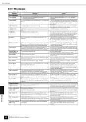
... Owner's Manual Recheck all word clock connections and internal parameters. Data is being received from the computer. The DME64N/24N clock is not in sync with the clock of the card installed in I/O slot 4. Data is being received from the computer. Error Messages Message SLOT4 Sync Err Synchronizing Do...turn power off while the unit displays this message. Do NOT turn power off while the unit displays this message. Make sure that the DME64N and the card or external source supplying the word clock are set to use the same word clock. - - A usable word clock signal is not ...
... Owner's Manual Recheck all word clock connections and internal parameters. Data is being received from the computer. The DME64N/24N clock is not in sync with the clock of the card installed in I/O slot 4. Data is being received from the computer. Error Messages Message SLOT4 Sync Err Synchronizing Do...turn power off while the unit displays this message. Do NOT turn power off while the unit displays this message. Make sure that the DME64N and the card or external source supplying the word clock are set to use the same word clock. - - A usable word clock signal is not ...

Owners Manual
Page 73
... GPI (General Purpose Interface) Initial Settings MAC (Media Access Control) Address MIDI (Musical Instrument Digital Interface) Mini YGDAI (Yamaha General Digital Audio Interface) card Explanations A physical specification for a 100 Mbps Ethernet network connection using 2-conductor Category 3 UTP cable included in... Ideal for I/O cards that can also be installed to complete the connection. Transfer speeds have the same address. Simply insert the wire into the plug slot, tighten the screw, and plug into the socket to Yamaha audio products. References DME64N/DME24N Owner's Manual...
... GPI (General Purpose Interface) Initial Settings MAC (Media Access Control) Address MIDI (Musical Instrument Digital Interface) Mini YGDAI (Yamaha General Digital Audio Interface) card Explanations A physical specification for a 100 Mbps Ethernet network connection using 2-conductor Category 3 UTP cable included in... Ideal for I/O cards that can also be installed to complete the connection. Transfer speeds have the same address. Simply insert the wire into the plug slot, tighten the screw, and plug into the socket to Yamaha audio products. References DME64N/DME24N Owner's Manual...

Owners Manual
Page 75
... Amplifier Setup (HA) Page 52, 54 Head Margin 54 High-pass Filter 53 High-pass Filter Frequency 53 [HOME] Button 15 Host 50 HPF 53 DME64N/DME24N Owner's Manual 75 Index +48V 53 [E F] Buttons 15 100Base-TX (Glossary 70 10Base-T (Glossary 70 [96kHz] [88.2kHz] [48kHz] [44.1kHz... Society/European Broadcasting Union) (Glossary 70 area 9 audio 11 B Band Output Level 40 Battery 45 BNC (Bayonet Nut Connector, or Bayonet Neill Concelman) (Glossary 70 C cable clamp 18 Calibration Info 52 [CANCEL] Button 15 Card Name 49 CASCAD Page 54 Cascade (Glossary 70 Cascade (WCLK Page 49 ...
... Amplifier Setup (HA) Page 52, 54 Head Margin 54 High-pass Filter 53 High-pass Filter Frequency 53 [HOME] Button 15 Host 50 HPF 53 DME64N/DME24N Owner's Manual 75 Index +48V 53 [E F] Buttons 15 100Base-TX (Glossary 70 10Base-T (Glossary 70 [96kHz] [88.2kHz] [48kHz] [44.1kHz... Society/European Broadcasting Union) (Glossary 70 area 9 audio 11 B Band Output Level 40 Battery 45 BNC (Bayonet Nut Connector, or Bayonet Neill Concelman) (Glossary 70 C cable clamp 18 Calibration Info 52 [CANCEL] Button 15 Card Name 49 CASCAD Page 54 Cascade (Glossary 70 Cascade (WCLK Page 49 ...