
DME32 Owners Manual
Page 6
... Manual 7 Installing the DME32 7 2 Getting Started 9 First Steps 10 Connecting to a PC 10 Connecting the Power Cord 11 Turning On & Off the DME32 11 Installing DME Manager 12 Upgrading & Reinstalling DME Manager 12 Starting DME Manager 12 Quitting DME Manager 13 DME Manager & Windows 13 Installing the USB Driver 13 Checking the Driver is Installed Correctly 14 USB Operating Notes 14 3 Touring the DME32 15 Front Panel 16 Rear Panel 19 4 Touring DME Manager 21 Modes...
... Manual 7 Installing the DME32 7 2 Getting Started 9 First Steps 10 Connecting to a PC 10 Connecting the Power Cord 11 Turning On & Off the DME32 11 Installing DME Manager 12 Upgrading & Reinstalling DME Manager 12 Starting DME Manager 12 Quitting DME Manager 13 DME Manager & Windows 13 Installing the USB Driver 13 Checking the Driver is Installed Correctly 14 USB Operating Notes 14 3 Touring the DME32 15 Front Panel 16 Rear Panel 19 4 Touring DME Manager 21 Modes...

DME32 Owners Manual
Page 7
... 76 Linking Component Parameters 78 Customizing Component Properties 80 Changing the Size of Rotary Controls & Sliders 82 Using Password Protection 83 Assigning the User Define Button 86 Printing 87 8 Component Guide Part I 89 Automatic Mixer 90 Cascade 92 Crossover 93 Crossover Processor 102 Delay 120 Delayed Mixer 122 Dynamics 125 9 Component Guide Part II 141 Effect 142 EQ 162 Fader 165 Filter 166 Input/Output 170 Matrix Mixer 171 Meter 174 Misc 175 DME32-Owner's Manual
... 76 Linking Component Parameters 78 Customizing Component Properties 80 Changing the Size of Rotary Controls & Sliders 82 Using Password Protection 83 Assigning the User Define Button 86 Printing 87 8 Component Guide Part I 89 Automatic Mixer 90 Cascade 92 Crossover 93 Crossover Processor 102 Delay 120 Delayed Mixer 122 Dynamics 125 9 Component Guide Part II 141 Effect 142 EQ 162 Fader 165 Filter 166 Input/Output 170 Matrix Mixer 171 Meter 174 Misc 175 DME32-Owner's Manual
DME32 Owners Manual
Page 11
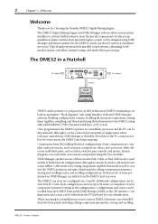
... control the DME32 system in a Nutshell 32 inputs SCENE NO. 88 48kHz 44.1kHz LOCK EMERGENCY CONFIGURATION SCENE XXXXXYAMAHAXDME32 XDigitalXMixingXEngine COMPONENT PARAMETER VALUE PROTECT UTILITY CARD DATA USER DEFINE INC DEC SCENE RECALL 7 8 9 4 5 6 1 2 3 STORE 0 RECALL POWER ON OFF DIGITAL MIXING ENGINE Control DME Manager 32 outputs DME32 audio systems, or configurations as faders, switches, pan controls, and meters. Configurations and scenes can then be designed using either RS232/RS422, USB (Universal Serial Bus...
... control the DME32 system in a Nutshell 32 inputs SCENE NO. 88 48kHz 44.1kHz LOCK EMERGENCY CONFIGURATION SCENE XXXXXYAMAHAXDME32 XDigitalXMixingXEngine COMPONENT PARAMETER VALUE PROTECT UTILITY CARD DATA USER DEFINE INC DEC SCENE RECALL 7 8 9 4 5 6 1 2 3 STORE 0 RECALL POWER ON OFF DIGITAL MIXING ENGINE Control DME Manager 32 outputs DME32 audio systems, or configurations as faders, switches, pan controls, and meters. Configurations and scenes can then be designed using either RS232/RS422, USB (Universal Serial Bus...

DME32 Owners Manual
Page 15
... crossovers, dynamics, filters, GEQ, PEQ, effects, etc • Part-type components include faders, meters, switches, pan controls, etc • Create custom components using User Modules • Copy frequently used controls to custom control windows • Customize the size of rotary controls and sliders Edit mode • Drag and drop components onto configuration windows • Use standard cut, copy, and paste commands to edit components •...
... crossovers, dynamics, filters, GEQ, PEQ, effects, etc • Part-type components include faders, meters, switches, pan controls, etc • Create custom components using User Modules • Copy frequently used controls to custom control windows • Customize the size of rotary controls and sliders Edit mode • Drag and drop components onto configuration windows • Use standard cut, copy, and paste commands to edit components •...
DME32 Owners Manual
Page 17
First Steps 10 Connecting to a PC 10 Connecting the Power Cord 11 Turning On & Off the DME32 11 Installing DME Manager 12 Upgrading & Reinstalling DME Manager 12 Starting DME Manager 12 Quitting DME Manager 13 DME Manager & Windows 13 Installing the USB Driver 13 Checking the Driver is Installed Correctly 14 USB Operating Notes 14 DME32-Owner's Manual Getting Started 9 Getting Started 2 In this chapter...
First Steps 10 Connecting to a PC 10 Connecting the Power Cord 11 Turning On & Off the DME32 11 Installing DME Manager 12 Upgrading & Reinstalling DME Manager 12 Starting DME Manager 12 Quitting DME Manager 13 DME Manager & Windows 13 Installing the USB Driver 13 Checking the Driver is Installed Correctly 14 USB Operating Notes 14 DME32-Owner's Manual Getting Started 9 Getting Started 2 In this chapter...

DME32 Owners Manual
Page 19
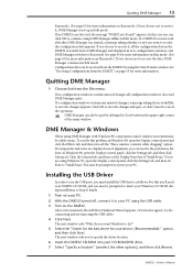
... to install the USB driver in order to the DME32 and is ideal for systems where the DME32 rear panel is turned on the DME32, press the [POWER] switch. DME32-Owner's Manual SCENE NO. 88 48kHz 44.1kHz LOCK EMERGENCY CONFIGURATION SCENE XXXXXYAMAHAXDME32 XDigitalXMixingXEngine COMPONENT PARAMETER VALUE PROTECT UTILITY CARD DATA USER DEFINE INC DEC SCENE RECALL 7 8 9 4 5 6 1 2 3 STORE 0 RECALL POWER ON OFF DIGITAL MIXING ENGINE USB port USB cable USB port Connecting the Power Cord AC IN Warning: Turn off the DME32, press the [POWER] switch. The...
... to install the USB driver in order to the DME32 and is ideal for systems where the DME32 rear panel is turned on the DME32, press the [POWER] switch. DME32-Owner's Manual SCENE NO. 88 48kHz 44.1kHz LOCK EMERGENCY CONFIGURATION SCENE XXXXXYAMAHAXDME32 XDigitalXMixingXEngine COMPONENT PARAMETER VALUE PROTECT UTILITY CARD DATA USER DEFINE INC DEC SCENE RECALL 7 8 9 4 5 6 1 2 3 STORE 0 RECALL POWER ON OFF DIGITAL MIXING ENGINE USB port USB cable USB port Connecting the Power Cord AC IN Warning: Turn off the DME32, press the [POWER] switch. The...
DME32 Owners Manual
Page 21
... Windows 98, open the Display control panel and click the Effects tab, and then turn off , connect it to continue using Windows 95, open the Display control panel, click the Settings tab, and then click Advanced. After a few moments, the Add New Hardware Wizard appears. (If it handy. 1 Turn on Run mode.) If you to save the changes and quit, or click Cancel to cancel the operation...
... Windows 98, open the Display control panel and click the Effects tab, and then turn off , connect it to continue using Windows 95, open the Display control panel, click the Settings tab, and then click Advanced. After a few moments, the Add New Hardware Wizard appears. (If it handy. 1 Turn on Run mode.) If you to save the changes and quit, or click Cancel to cancel the operation...

DME32 Owners Manual
Page 109
... table ON/OFF See the following table. This control's label depends on and off Selects the delay units for the low and high channels. DME32-Owner's Manual Delay times can be specified in the units chosen using the DELAY SCALE buttons (linked to ms control) Turns the delay on the Delay Scale setting. Section Parameter Range Description INPUT OUTPUT LOW LEVEL MUTE LEVEL MUTE PHASE OUTPUT HIGH LEVEL MUTE PHASE -Infinity dB to 0.0 dB ON/OFF...
... table ON/OFF See the following table. This control's label depends on and off Selects the delay units for the low and high channels. DME32-Owner's Manual Delay times can be specified in the units chosen using the DELAY SCALE buttons (linked to ms control) Turns the delay on the Delay Scale setting. Section Parameter Range Description INPUT OUTPUT LOW LEVEL MUTE LEVEL MUTE PHASE OUTPUT HIGH LEVEL MUTE PHASE -Infinity dB to 0.0 dB ON/OFF...

DME32 Owners Manual
Page 113
... control window features INPUT, OUTPUT, and control sections, with delay, 3-band PEQ, and compressor on each channel. The 3-Way Processor component features one input and three outputs: High, Mid, and Low. Section INPUT OUTPUT LOW OUTPUT MID OUTPUT HIGH Parameter LEVEL MUTE LEVEL MUTE PHASE LEVEL MUTE PHASE LEVEL MUTE PHASE Range Description -Infinity dB to 0.0 dB Adjusts the input signal level ON/OFF Mutes the input -Infinity dB to 0.0 dB Adjusts the low output signal level ON/OFF Mutes the low output NOR/REV Inverts the low output signal...
... control window features INPUT, OUTPUT, and control sections, with delay, 3-band PEQ, and compressor on each channel. The 3-Way Processor component features one input and three outputs: High, Mid, and Low. Section INPUT OUTPUT LOW OUTPUT MID OUTPUT HIGH Parameter LEVEL MUTE LEVEL MUTE PHASE LEVEL MUTE PHASE LEVEL MUTE PHASE Range Description -Infinity dB to 0.0 dB Adjusts the input signal level ON/OFF Mutes the input -Infinity dB to 0.0 dB Adjusts the low output signal level ON/OFF Mutes the low output NOR/REV Inverts the low output signal...

DME32 Owners Manual
Page 134
... or externally triggered via the sidechain input. The Stereo Compressor component features two inputs, two outputs, and a sidechain input. The Compressor control window features a gain reduction (GR) meter, compressor curve, output level meter, and compressor controls. The gain reduction (GR) meter displays the amount of the Compressor. 128 Chapter 8-Component Guide Part I Compressor & Stereo Compressor A compressor essentially "squeezes" a signal's dynamic range, making it easier to the output signal level, while the horizontal axis corresponds DME32-Owner's Manual The Compressor...
... or externally triggered via the sidechain input. The Stereo Compressor component features two inputs, two outputs, and a sidechain input. The Compressor control window features a gain reduction (GR) meter, compressor curve, output level meter, and compressor controls. The gain reduction (GR) meter displays the amount of the Compressor. 128 Chapter 8-Component Guide Part I Compressor & Stereo Compressor A compressor essentially "squeezes" a signal's dynamic range, making it easier to the output signal level, while the horizontal axis corresponds DME32-Owner's Manual The Compressor...

DME32 Owners Manual
Page 149
... Low-pass filter cutoff frequency (THRU = filter off) 1 Type of early reflection controls, input level meter, stereo output level meters, and reflection pattern type selector. Parameter Range Description ROOMSIZE LIVENESS INI.DLY DIFF. S-Hall (small hall), L-Hall (large hall), Random, Reverse, Plate, Spring DME32-Owner's Manual 144 Chapter 9-Component Guide Part II Early Ref. The Early Ref. control window consists...
... Low-pass filter cutoff frequency (THRU = filter off) 1 Type of early reflection controls, input level meter, stereo output level meters, and reflection pattern type selector. Parameter Range Description ROOMSIZE LIVENESS INI.DLY DIFF. S-Hall (small hall), L-Hall (large hall), Random, Reverse, Plate, Spring DME32-Owner's Manual 144 Chapter 9-Component Guide Part II Early Ref. The Early Ref. control window consists...
DME32 Owners Manual
Page 236
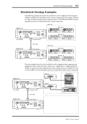
... 12 +10 -20 +10 -20 GAIN GAIN 13/14 15/16 0 10 LEVEL MONITOR OUT 0 10 LEVEL PHONES UTILITY MIDI SETUP VIEW PAN/ DYNAMICS EQ/ATT Ø/DELAY ROUTING FADER MODE EFFECT 1 EFFECT 2 OPTION I /O cards for analog inputs and outputs. DME32 #2 automatically receives its wordclock from the cascade connection. TRACK SELECT EDIT UNDO/ REDO JOG ON DIGITAL MULTITRACK RECORDER PROJECT SEARCH LAST REC IN OUT SET AUTO PUNCH RTN TO ZERO ROLL...
... 12 +10 -20 +10 -20 GAIN GAIN 13/14 15/16 0 10 LEVEL MONITOR OUT 0 10 LEVEL PHONES UTILITY MIDI SETUP VIEW PAN/ DYNAMICS EQ/ATT Ø/DELAY ROUTING FADER MODE EFFECT 1 EFFECT 2 OPTION I /O cards for analog inputs and outputs. DME32 #2 automatically receives its wordclock from the cascade connection. TRACK SELECT EDIT UNDO/ REDO JOG ON DIGITAL MULTITRACK RECORDER PROJECT SEARCH LAST REC IN OUT SET AUTO PUNCH RTN TO ZERO ROLL...
DME32 Owners Manual
Page 252
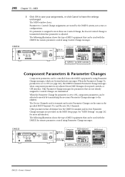
... used to Control Changes are stored by using Parameter Change messages, which are System Exclusive messages. See "MIDI Settings" on the MIDI Setup page. DME32 SCENE NO. 88 48kHz 44.1kHz LOCK EMERGENCY CONFIGURATION SCENE XXXXXYAMAHAXDME32 XDigitalXMixingXEngine COMPONENT PARAMETER VALUE PROTECT UTILITY CARD DATA USER DEFINE INC DEC SCENE RECALL 7 8 9 4 5 6 1 2 3 STORE 0 RECALL POWER ON OFF DIGITAL MIXING ENGINE MIDI IN Computer MIDI OUT Lighting MIDI keyboard MIDI Sampler MIDI controller MIDI mixer PAD 26dB 26dB PHANTOM +48V OFF ON INPUT...
... used to Control Changes are stored by using Parameter Change messages, which are System Exclusive messages. See "MIDI Settings" on the MIDI Setup page. DME32 SCENE NO. 88 48kHz 44.1kHz LOCK EMERGENCY CONFIGURATION SCENE XXXXXYAMAHAXDME32 XDigitalXMixingXEngine COMPONENT PARAMETER VALUE PROTECT UTILITY CARD DATA USER DEFINE INC DEC SCENE RECALL 7 8 9 4 5 6 1 2 3 STORE 0 RECALL POWER ON OFF DIGITAL MIXING ENGINE MIDI IN Computer MIDI OUT Lighting MIDI keyboard MIDI Sampler MIDI controller MIDI mixer PAD 26dB 26dB PHANTOM +48V OFF ON INPUT...
DME32 Owners Manual
Page 256
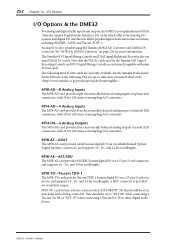
The Yamaha 01V Digital Mixing Console and D24 Digital Multitrack Recorder also use mini YGDAI I /O is provided for more information. The following URL for up-to-date news on page 256 for wordclock output. DME32-Owner's Manual See the Yamaha Professional Audio Web site at the following mini YGDAI cards are not interchangeable with 20-bit 128-times oversampling A/D converters. Analog I /O cards. MY8-AE-AES/EBU The MY8...
The Yamaha 01V Digital Mixing Console and D24 Digital Multitrack Recorder also use mini YGDAI I /O is provided for more information. The following URL for up-to-date news on page 256 for wordclock output. DME32-Owner's Manual See the Yamaha Professional Audio Web site at the following mini YGDAI cards are not interchangeable with 20-bit 128-times oversampling A/D converters. Analog I /O cards. MY8-AE-AES/EBU The MY8...
DME32 Owners Manual
Page 264
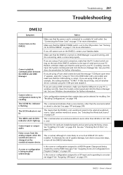
... the DME32 POWER switch is not lit. Cannot input or output audio. To eliminate the risk of serial port on the rear of the DME32 conforms to the type of speaker damage, turn down your Windows documentation for further information. See "Assigning GPI Inputs" on page 229. DME32-Owner's Manual Make sure that a scene memory other than the one last recalled or stored is correct. If you are using a USB connection, make...
... the DME32 POWER switch is not lit. Cannot input or output audio. To eliminate the risk of serial port on the rear of the DME32 conforms to the type of speaker damage, turn down your Windows documentation for further information. See "Assigning GPI Inputs" on page 229. DME32-Owner's Manual Make sure that a scene memory other than the one last recalled or stored is correct. If you are using a USB connection, make...

DME32 Owners Manual
Page 265
... receive MIDI messages. See "MIDI Settings" on the MIDI Setup window. DME32-Owner's Manual Check the settings on page 242. See "MIDI Settings" on page 246. Is Scene Recall Only mode enabled? Is the parameter being transmitted is lit. See "Assigning Component Parameters to Parameter Change messages from an external MIDI device? Multiple-unit operation does not work. Is the parameter responding to Control Changes" on page 242. See "Assigning the User Define Button...
... receive MIDI messages. See "MIDI Settings" on the MIDI Setup window. DME32-Owner's Manual Check the settings on page 242. See "MIDI Settings" on page 246. Is Scene Recall Only mode enabled? Is the parameter being transmitted is lit. See "Assigning Component Parameters to Parameter Change messages from an external MIDI device? Multiple-unit operation does not work. Is the parameter responding to Control Changes" on page 242. See "Assigning the User Define Button...
DME32 Owners Manual
Page 287
... GPI input can understand. The DME32's system software is engaged. Also known as mixers, compressors, effects, and crossovers, while others are combined, the gain over the entire range is the same for transferring digital audio data between professional digital audio equipment. Eight channels of components and wires that the DME32 can be assigned to the DME32. The DME32 can be reprogrammed. When the output signal from its virtually linear phase response...
... GPI input can understand. The DME32's system software is engaged. Also known as mixers, compressors, effects, and crossovers, while others are combined, the gain over the entire range is the same for transferring digital audio data between professional digital audio equipment. Eight channels of components and wires that the DME32 can be assigned to the DME32. The DME32 can be reprogrammed. When the output signal from its virtually linear phase response...

DME32 Owners Manual
Page 290
... scenes offline 76 user controls 191 user modules 196 Diagram, printing 87 Dimensions 277 Display 16 DME Manager error messages 271 features 6 installing 12 password protection 83 quitting 13 reinstalling 12 starting 12 upgrading 12 Windows 13 DME32 dimensions 277 error messages 270 features 4 front panel 16 in a nutshell 2 initializing 210 rear panel 19 turning on and off 11 Dragging components from the component list 47 rotary controls 32 sliders 32 DSP power meter...
... scenes offline 76 user controls 191 user modules 196 Diagram, printing 87 Dimensions 277 Display 16 DME Manager error messages 271 features 6 installing 12 password protection 83 quitting 13 reinstalling 12 starting 12 upgrading 12 Windows 13 DME32 dimensions 277 error messages 270 features 4 front panel 16 in a nutshell 2 initializing 210 rear panel 19 turning on and off 11 Dragging components from the component list 47 rotary controls 32 sliders 32 DSP power meter...
DME32 Owners Manual
Page 292
... DME32s 236 omni settings 242 OUT port 242 parameter changes 248 program change assign table 279 saving settings 249 settings 242 MIDI command 36 mini YGDAI card specifications 253 cards 252 definition 288 Minimizing configuration windows 26 Misc components 175 Mod delay component 148 Mod filter component 159 Mode menu 35 Modes 22 Module command 35 Mono delay component 146 Multiple DME32s about 236 cascade connections 237 configuration window sections 29 configuration windows...
... DME32s 236 omni settings 242 OUT port 242 parameter changes 248 program change assign table 279 saving settings 249 settings 242 MIDI command 36 mini YGDAI card specifications 253 cards 252 definition 288 Minimizing configuration windows 26 Misc components 175 Mod delay component 148 Mod filter component 159 Mode menu 35 Modes 22 Module command 35 Mono delay component 146 Multiple DME32s about 236 cascade connections 237 configuration window sections 29 configuration windows...
DME32 Owners Manual
Page 294
... USB checking the driver 14 connecting 11 definition 288 driver installation 14 operating notes 14 port 17 USB driver 14 User controls copying controls 191 deleting 191 pasting 191 using 190 USER DEFINE button about 18 assigning 86 using 201 User define button command 36 User modules deleting 196 loading 195 properties 80 saving 194 using 193 wiring 193 UTILITY button and indicator 18 V VALUE button and indicator 18 Version DME Manager 38 DME32 firmware...
... USB checking the driver 14 connecting 11 definition 288 driver installation 14 operating notes 14 port 17 USB driver 14 User controls copying controls 191 deleting 191 pasting 191 using 190 USER DEFINE button about 18 assigning 86 using 201 User define button command 36 User modules deleting 196 loading 195 properties 80 saving 194 using 193 wiring 193 UTILITY button and indicator 18 V VALUE button and indicator 18 Version DME Manager 38 DME32 firmware...


