
DEQ7 Owners Manual Image
Page 2
... CONTROL L/R 76 UTILITY FUNCTIONS 8 18. BAND PASS UR 78 MIDI BANK & CHANNEL ASSIGNMENT 9 20. NOTCH 82 INPUT ATTENUATER ADJUSTMENT 13 24. 6 - PEQ FC 84 SPECIFICATIONS 18 26. PEQ LEVEL 85 DESCRIPTIONS OF THE PROGRAMS 59 27. GEQ 2/3 oct UR N 65 DIMENSIONS 91 7. Your DEQ7 Digital Equalizer uses the most advanced Yamaha digital signal processing technology to read this operation manually thoroughly before using the DEQ7, in order tofully take advantage of recording, audio...
... CONTROL L/R 76 UTILITY FUNCTIONS 8 18. BAND PASS UR 78 MIDI BANK & CHANNEL ASSIGNMENT 9 20. NOTCH 82 INPUT ATTENUATER ADJUSTMENT 13 24. 6 - PEQ FC 84 SPECIFICATIONS 18 26. PEQ LEVEL 85 DESCRIPTIONS OF THE PROGRAMS 59 27. GEQ 2/3 oct UR N 65 DIMENSIONS 91 7. Your DEQ7 Digital Equalizer uses the most advanced Yamaha digital signal processing technology to read this operation manually thoroughly before using the DEQ7, in order tofully take advantage of recording, audio...
DEQ7 Owners Manual Image
Page 3
... the DEQ7 contains digital circuitry, it may cause interference and noise if placed too close to replace the battery yourself. If such a problem does occur, move the DEQ7 further away from locations where it with the internal circuitry will appear on the rear panel matches your local AC mains source. If the battery voltage falls below the safe level, however, the "***WARNING*** LOW BATTERY" display will...
... the DEQ7 contains digital circuitry, it may cause interference and noise if placed too close to replace the battery yourself. If such a problem does occur, move the DEQ7 further away from locations where it with the internal circuitry will appear on the rear panel matches your local AC mains source. If the battery voltage falls below the safe level, however, the "***WARNING*** LOW BATTERY" display will...
DEQ7 Owners Manual Image
Page 4
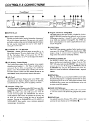
... lights at levels greater than +18 dBm when the level control is set at "7" and the input level switch is fed to 0 dB. LCD Panel The LCD (Liquid Crystal Display) panel is active. When the LED display is used to change to memory number assignment, MIDI bulk dump control and seconds or feet display selection. 0 PROTECT ONIOFF Key The PROTECT ON/OFF key is continuously lit, the effect corresponding to +4 dB. 0 LED Memory Number Display This 2-digit...
... lights at levels greater than +18 dBm when the level control is set at "7" and the input level switch is fed to 0 dB. LCD Panel The LCD (Liquid Crystal Display) panel is active. When the LED display is used to change to memory number assignment, MIDI bulk dump control and seconds or feet display selection. 0 PROTECT ONIOFF Key The PROTECT ON/OFF key is continuously lit, the effect corresponding to +4 dB. 0 LED Memory Number Display This 2-digit...
DEQ7 Owners Manual Image
Page 5
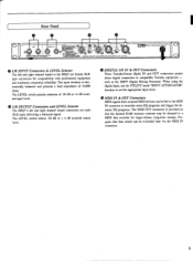
... nominal output level. 00 DIGITAL I ()YAMAHA DIGITAL PFICGRAMMABLE EQUALIZER MODEL DEOT ® LIR INPUT Connectors & LEVEL Selector The left and right channel output connectors are female XLR type connectors for large-volume, long-term storage. such as the DMP7 Digital Mixing Processor. When using the digital input, use the UTILITY mode "INPUT ATTENUATOR" function to set the appropriate input level. 45 MIDI IN & OUT Connectors MIDI signals from external MIDI devices can be dumped to compatible Yamaha equipment - Rear Panel 16 0 MIDI...
... nominal output level. 00 DIGITAL I ()YAMAHA DIGITAL PFICGRAMMABLE EQUALIZER MODEL DEOT ® LIR INPUT Connectors & LEVEL Selector The left and right channel output connectors are female XLR type connectors for large-volume, long-term storage. such as the DMP7 Digital Mixing Processor. When using the digital input, use the UTILITY mode "INPUT ATTENUATOR" function to set the appropriate input level. 45 MIDI IN & OUT Connectors MIDI signals from external MIDI devices can be dumped to compatible Yamaha equipment - Rear Panel 16 0 MIDI...

DEQ7 Owners Manual Image
Page 6
.... FILTER LEVEL 30. DYN. GEQ 1/3 oct Lch N 12. DYN. The LED memory number display will stop flashing and the selected program will be engaged. • M. GEQ 2/3 oct UR N 7. GEQ 1/2 oct L=R 8. Hold either of each effect program and its contents have not yet been recalled. GENERAL OPERATION MEMORY CONFIGURATION The DEQ7 has a total of the preset programs. SELECTING AN EQ PROGRAM 6 'CD Press the program selection or Q key...
.... FILTER LEVEL 30. DYN. GEQ 1/3 oct Lch N 12. DYN. The LED memory number display will stop flashing and the selected program will be engaged. • M. GEQ 2/3 oct UR N 7. GEQ 1/2 oct L=R 8. Hold either of each effect program and its contents have not yet been recalled. GENERAL OPERATION MEMORY CONFIGURATION The DEQ7 has a total of the preset programs. SELECTING AN EQ PROGRAM 6 'CD Press the program selection or Q key...
DEQ7 Owners Manual Image
Page 7
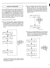
... or decrementing. Either key can be edited. Using program 1 (GEQ 1/1 oct L=R) as the parameters described above. Each time the PARAMETER key is recalled. The PARAMETER key is used to access the parameters which may be called . EDITING PARAMETERS Each of the DEQ7 EQ programs has a number of internal parameters which are unique to each program, and the DELAY/LEVEL key is a boost/cut setting between -18 dB...
... or decrementing. Either key can be edited. Using program 1 (GEQ 1/1 oct L=R) as the parameters described above. Each time the PARAMETER key is recalled. The PARAMETER key is used to access the parameters which may be called . EDITING PARAMETERS Each of the DEQ7 EQ programs has a number of internal parameters which are unique to each program, and the DELAY/LEVEL key is a boost/cut setting between -18 dB...

DEQ7 Owners Manual Image
Page 8
... edit any changes you need to continuously increment or decrement the parameters by simultaneously pressing the PARAMETER and or V keys. The LED memory number display will stop flashing the stored memory location will have made will be re-programmed. If, however, you select and recall a new effect without first storing your own title using the program select Q and 7 keys. If no data has been...
... edit any changes you need to continuously increment or decrement the parameters by simultaneously pressing the PARAMETER and or V keys. The LED memory number display will stop flashing the stored memory location will have made will be re-programmed. If, however, you select and recall a new effect without first storing your own title using the program select Q and 7 keys. If no data has been...
DEQ7 Owners Manual Image
Page 9
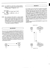
... control keys, thus changing the EQ setting. when the control-panel BYPASS key or BYPASS footswitch is directly routed to the output terminals (i.e. While the BYPASS indicator is lit the DEQ7 program is bypassed and the input signal is pressed - memoir PPIPASS bypassed mos BY PASS PROTECT If, for example, you are ignored when PROTECT is for foot-bypass control. The indicator LED in a memory...
... control keys, thus changing the EQ setting. when the control-panel BYPASS key or BYPASS footswitch is directly routed to the output terminals (i.e. While the BYPASS indicator is lit the DEQ7 program is bypassed and the input signal is pressed - memoir PPIPASS bypassed mos BY PASS PROTECT If, for example, you are ignored when PROTECT is for foot-bypass control. The indicator LED in a memory...

DEQ7 Owners Manual Image
Page 10
... the UTILITY key a few times until the UTILITY mode is exited: INPUT ATTENUATOR (Lch) -o INPUT ATT'ENUATOR (Rch) -o CONVERT -o DELAY DISPLAY -o TITLE EDIT MIDI CONTROL (ch) -' MIDI CONTROL (BANK) -0 MIDI PGM CHANGE -o MIDI BULK DUMP (BANK) -0 MIDI BULK DUMP (MEMORY) -0 exit UTILITY mode. RAM (31-90) ONLY TITLE EDIT The available characters are used to each position. GEC 1/1oct L=R TITLE EDIT LEVEL * Since the contents of these programs produces the...
... the UTILITY key a few times until the UTILITY mode is exited: INPUT ATTENUATOR (Lch) -o INPUT ATT'ENUATOR (Rch) -o CONVERT -o DELAY DISPLAY -o TITLE EDIT MIDI CONTROL (ch) -' MIDI CONTROL (BANK) -0 MIDI PGM CHANGE -o MIDI BULK DUMP (BANK) -0 MIDI BULK DUMP (MEMORY) -0 exit UTILITY mode. RAM (31-90) ONLY TITLE EDIT The available characters are used to each position. GEC 1/1oct L=R TITLE EDIT LEVEL * Since the contents of these programs produces the...
DEQ7 Owners Manual Image
Page 11
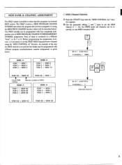
...: B PGM 1 = MEM 6 PGM 2 = MEM 7 PGM 3 = MEM 16 M MIDI Channel Selection 0 Press the UTILITY key until the "MIDI CONTROL ch=" func- ceived), or turn MIDI reception OFF. Before programming the assignments, however, it possible to set the MIDI channel (1 - 16), the OMNI mode (all channels can be programmed with different program number/memory number assignments is contained in a different "bank": A, B, C or D. tion appears. © Use the parameter editing and V keys to select specific programs via external MIDI control.
...: B PGM 1 = MEM 6 PGM 2 = MEM 7 PGM 3 = MEM 16 M MIDI Channel Selection 0 Press the UTILITY key until the "MIDI CONTROL ch=" func- ceived), or turn MIDI reception OFF. Before programming the assignments, however, it possible to set the MIDI channel (1 - 16), the OMNI mode (all channels can be programmed with different program number/memory number assignments is contained in a different "bank": A, B, C or D. tion appears. © Use the parameter editing and V keys to select specific programs via external MIDI control.

DEQ7 Owners Manual Image
Page 12
... number containing the effect which a new DEQ7 memory location number is exited. MIDI PGM CHANGE PGM 3 = MEM 3 PGM number STORE .=a1 CALL MIDI PGM CHANGE PGM 3 = MEM 36 MEM number NOTE: The program number/memory number assignments made are reset to program using the parameter editing and keys. The range of program change assignments are stored in the BANK selected in the previous MIDI CONTROL BANK function. MIS UTILIT UT LI MIDI PGM CHANGE PGM 1 = MEM 1 MIDI CONTROL BANK:A s DFTEELEAY/ DELAY LEVEL MIDI CONTROL...
... number containing the effect which a new DEQ7 memory location number is exited. MIDI PGM CHANGE PGM 3 = MEM 3 PGM number STORE .=a1 CALL MIDI PGM CHANGE PGM 3 = MEM 36 MEM number NOTE: The program number/memory number assignments made are reset to program using the parameter editing and keys. The range of program change assignments are stored in the BANK selected in the previous MIDI CONTROL BANK function. MIS UTILIT UT LI MIDI PGM CHANGE PGM 1 = MEM 1 MIDI CONTROL BANK:A s DFTEELEAY/ DELAY LEVEL MIDI CONTROL...

DEQ7 Owners Manual Image
Page 13
...). @ Press the UTILITY key a few times until the UTILITY mode is used to the "TRANSMIT?" MIDI BULK DUMP BANK:A TRANSMIT? 0ELAV LEVEL MIDI BULK DUMP BANK:B TRANSMIT? Press the program selection Q key to perform another bulk dump operation. 11 Selected bank STORE RECALL MIDI BULK DUMP MEMORY EXECUTE MIDI BULK DUMP MEMORY COMPLETE * Press the program selection a key to return to dump the MIDI program change number assignment table from the selected...
...). @ Press the UTILITY key a few times until the UTILITY mode is used to the "TRANSMIT?" MIDI BULK DUMP BANK:A TRANSMIT? 0ELAV LEVEL MIDI BULK DUMP BANK:B TRANSMIT? Press the program selection Q key to perform another bulk dump operation. 11 Selected bank STORE RECALL MIDI BULK DUMP MEMORY EXECUTE MIDI BULK DUMP MEMORY COMPLETE * Press the program selection a key to return to dump the MIDI program change number assignment table from the selected...

DEQ7 Owners Manual Image
Page 14
... until the UTILITY mode is between speaker systems in the receiving DEQ7. It can also be used to compensate for physical distances between 31 and 90, it will be stored in the correspondingly numbered location in large sound installations. 0 Press the UTILITY key a few times until the DELAY DISPLAY function appears. L=R L/R Display corresponds to the equivalent L/R types, thus allowing independent programming of program selected. If...
... until the UTILITY mode is between speaker systems in the receiving DEQ7. It can also be used to compensate for physical distances between 31 and 90, it will be stored in the correspondingly numbered location in large sound installations. 0 Press the UTILITY key a few times until the DELAY DISPLAY function appears. L=R L/R Display corresponds to the equivalent L/R types, thus allowing independent programming of program selected. If...
DEQ7 Owners Manual Image
Page 15
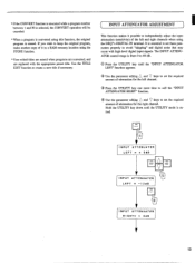
... UTILITY mode is exited. Hold the UTILITY key down until the "INPUT ATTENUATOR LEFT" function appears. © Use the parameter editing Q and V keys to avoid "skipping" and digital noise that may occur with the appropriate preset title. INPUT ATTENUATOR ADJUSTMENT This function makes it in a RAM memory location using the STORE function. * User-edited titles are erased when programs are converted, and are replaced with high-level digital input signals. INPUT ATTENUATER...
... UTILITY mode is exited. Hold the UTILITY key down until the "INPUT ATTENUATOR LEFT" function appears. © Use the parameter editing Q and V keys to avoid "skipping" and digital noise that may occur with the appropriate preset title. INPUT ATTENUATOR ADJUSTMENT This function makes it in a RAM memory location using the STORE function. * User-edited titles are erased when programs are converted, and are replaced with high-level digital input signals. INPUT ATTENUATER...

DEQ7 Owners Manual Image
Page 16
... BANK display is received from external equipment. The transmitted data consists of the contents of MIDI program change assignment table (assignment of the specified memory number. The data transmitted consists of the program change numbers to memory numbers). STATUS ID NO. Transmission Conditions BULK DATA $F0, $43, Son PARAMETER CHANGE SF0, $43, $1n MIDI CH o OFF OMNI, 1-16 MIDI OUT 2. SUB-STATUS FORMAT NO. BYTE COUNT BYTE COUNT HEADER DATA NAME MEMORY NO. Transmission Data...
... BANK display is received from external equipment. The transmitted data consists of the contents of MIDI program change assignment table (assignment of the specified memory number. The data transmitted consists of the program change numbers to memory numbers). STATUS ID NO. Transmission Conditions BULK DATA $F0, $43, Son PARAMETER CHANGE SF0, $43, $1n MIDI CH o OFF OMNI, 1-16 MIDI OUT 2. SUB-STATUS FORMAT NO. BYTE COUNT BYTE COUNT HEADER DATA NAME MEMORY NO. Transmission Data...

DEQ7 Owners Manual Image
Page 17
... PARAMETER L DELAY R DELAY L OUT LEVEL R OUT LEVEL PARAMETER 1 • PARAMETER 42 ppppppp 0 1 2 3 4 . • 45 pppp pppp 0-255 0-255 0-100 0-100 A 1 MEMORY BULK DUMP is performed 60 times, and a 1 BANK PROGRAM CHANGE ASSIGNMENT TABLE BULK DUMP is changed. STATUS IN NO. SUB-STATUS I I I 10000 (F0M) 0100001 1 (43H) 000 I nnnn (I CH) 0 PPPPPPP 0000dddd 0000dddd 1 1 1 101 1 1 (F7H) n=0 (channel no. 1)n =15 (channel no . 90 data Bank A data STATUS EOX...
... PARAMETER L DELAY R DELAY L OUT LEVEL R OUT LEVEL PARAMETER 1 • PARAMETER 42 ppppppp 0 1 2 3 4 . • 45 pppp pppp 0-255 0-255 0-100 0-100 A 1 MEMORY BULK DUMP is performed 60 times, and a 1 BANK PROGRAM CHANGE ASSIGNMENT TABLE BULK DUMP is changed. STATUS IN NO. SUB-STATUS I I I 10000 (F0M) 0100001 1 (43H) 000 I nnnn (I CH) 0 PPPPPPP 0000dddd 0000dddd 1 1 1 101 1 1 (F7H) n=0 (channel no. 1)n =15 (channel no . 90 data Bank A data STATUS EOX...

DEQ7 Owners Manual Image
Page 18
... (channel no . 161 PROGRAM NO. 0ccccccc c=0- 127 0 CONTROL CHANGE Control change assignment table of the currently active bank. STATUS I I nnnn (9nH) Okkkkkkk Ovvvvvvv n=0 (channel no. 1)15 (channel no. 161 k =0 (C-21-127(G8) v = 0 - 127 0 PROGRAM CHANGE When received, the memory number is recalled that is assigned to "MIDI Ft" reception is possible. When the CONTROL parameter is set to NOTE #, the filter frequency is set to the received program change number in the program change messages...
... (channel no . 161 PROGRAM NO. 0ccccccc c=0- 127 0 CONTROL CHANGE Control change assignment table of the currently active bank. STATUS I I nnnn (9nH) Okkkkkkk Ovvvvvvv n=0 (channel no. 1)15 (channel no. 161 k =0 (C-21-127(G8) v = 0 - 127 0 PROGRAM CHANGE When received, the memory number is recalled that is assigned to "MIDI Ft" reception is possible. When the CONTROL parameter is set to NOTE #, the filter frequency is set to the received program change number in the program change messages...
DEQ7 Owners Manual Image
Page 20
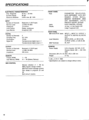
... Weight 3.7 kg * 0 dB = 0.775 V RMS * Specifications are subject to change number. SPECIFICATIONS ELECTRICAL CHARACTERISTICS Freq. Bulk dump & receive. Response 20 Hz - 20 kHz Dynamic Range 86 dB Harmonic Distortion 0.03% max. @ 1 kHz INPUT Number of Channels Sampling Freq. MIDI foot control message controls filter sweep in programs 25 and 28. FRONT PANEL Keys Jacks Display PARAMETER, DELAY/LEVEL, DATA INCREMENT, DATA DECREMENT, STORE, RECALL, MEMORY INCREMENT, MEMORY DECREMENT, UTILITY, PROTECT ON/OFF, BYPASS...
... Weight 3.7 kg * 0 dB = 0.775 V RMS * Specifications are subject to change number. SPECIFICATIONS ELECTRICAL CHARACTERISTICS Freq. Bulk dump & receive. Response 20 Hz - 20 kHz Dynamic Range 86 dB Harmonic Distortion 0.03% max. @ 1 kHz INPUT Number of Channels Sampling Freq. MIDI foot control message controls filter sweep in programs 25 and 28. FRONT PANEL Keys Jacks Display PARAMETER, DELAY/LEVEL, DATA INCREMENT, DATA DECREMENT, STORE, RECALL, MEMORY INCREMENT, MEMORY DECREMENT, UTILITY, PROTECT ON/OFF, BYPASS...

DEQ7 Owners Manual Image
Page 70
...La plage de controle de chaque bande vane de -18dB k ÷18dB. Die Signalentzerrung erfolgt ausschlieBlich auf dem linken Kanal. PARAMETER pARAM ETRE PARAMETER = DELAY/ LEVEL 1 L DELAY 2 R DELAY = PARA METER = BYPASS 3 L OUT LEVEL 4 R OUT LEVEL 1 L 40Hz... is bypassed (THRU) but the rightchannel delay and output level parameters are still active. Le facteur "Q" (largeur de...mono a 27 bandes qui couvre une plage de frequence de 40Hz a 16kHz. 9. TASTE FUR PARAMETERWAHL Nr. GEQ 1/3 oct Lch This is 4.5. TOUCHE DE SELECTION DE PARAMRTRE N. The equalizer functions on the left channel...
...La plage de controle de chaque bande vane de -18dB k ÷18dB. Die Signalentzerrung erfolgt ausschlieBlich auf dem linken Kanal. PARAMETER pARAM ETRE PARAMETER = DELAY/ LEVEL 1 L DELAY 2 R DELAY = PARA METER = BYPASS 3 L OUT LEVEL 4 R OUT LEVEL 1 L 40Hz... is bypassed (THRU) but the rightchannel delay and output level parameters are still active. Le facteur "Q" (largeur de...mono a 27 bandes qui couvre une plage de frequence de 40Hz a 16kHz. 9. TASTE FUR PARAMETERWAHL Nr. GEQ 1/3 oct Lch This is 4.5. TOUCHE DE SELECTION DE PARAMRTRE N. The equalizer functions on the left channel...
DEQ7 Owners Manual Image
Page 86
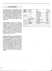
...) of the filter response can be set to low or high, and you can select a rising or falling sweep. The sweep is controlled either by a Yamaha FC7 or equivalent foot controller plugged into the front-panel FOOT CONTROL jack, or by a MIDI control change " de type "foot control" ou de "note ON" sur l'entree MIDI N. PEQ FC. ETER o BYPASS 3 L OUT LEVEL 4 R OUT LEVEL 1 GAIN 2 Q 3 SHIFT 4 CONTROL 1 BYPASS In diesem...
...) of the filter response can be set to low or high, and you can select a rising or falling sweep. The sweep is controlled either by a Yamaha FC7 or equivalent foot controller plugged into the front-panel FOOT CONTROL jack, or by a MIDI control change " de type "foot control" ou de "note ON" sur l'entree MIDI N. PEQ FC. ETER o BYPASS 3 L OUT LEVEL 4 R OUT LEVEL 1 GAIN 2 Q 3 SHIFT 4 CONTROL 1 BYPASS In diesem...


