
Owner's Manual
Page 7
... Manual (Start-up 1 Introducing the various components 2 Terms used in the "CS1D Operating Manual (Start-up 4 Connections (Standard mode 6 Connecting the console and engine (Standard mode 6 Connecting an analog input/output unit to the engine (Standard mode 8 Connecting a digital input/output unit ...to the engine (Standard mode 9 Connections (Mirror mode 10 Connecting the console and engines (Mirror mode 10 Connecting an analog input/output unit to the engines (Mirror mode 12 Connecting a digital input/output unit to...
... Manual (Start-up 1 Introducing the various components 2 Terms used in the "CS1D Operating Manual (Start-up 4 Connections (Standard mode 6 Connecting the console and engine (Standard mode 6 Connecting an analog input/output unit to the engine (Standard mode 8 Connecting a digital input/output unit ...to the engine (Standard mode 9 Connections (Mirror mode 10 Connecting the console and engines (Mirror mode 10 Connecting an analog input/output unit to the engines (Mirror mode 12 Connecting a digital input/output unit to...

Owner's Manual
Page 9
...For details on the function and operation of the controllers and connectors found on the top panel, rear panel, and front panel of the console (CS1D), refer to "CS1D Reference Manual (Hardware)." • For details on your attention to various tips for the first time, or if you follow the...that explains how to two engines of which only one is used. "Standard mode" in which one console is connected to one console is connected to connect the various components of the CS1D are taken from the actual screens on the software in mind. Screen shots shown in the screen. Example...
...For details on the function and operation of the controllers and connectors found on the top panel, rear panel, and front panel of the console (CS1D), refer to "CS1D Reference Manual (Hardware)." • For details on your attention to various tips for the first time, or if you follow the...that explains how to two engines of which only one is used. "Standard mode" in which one console is connected to one console is connected to connect the various components of the CS1D are taken from the actual screens on the software in mind. Screen shots shown in the screen. Example...
Owner's Manual
Page 10
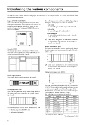
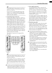
...ADAT AES/EBU ANALOG IN ANALOG IN ANALOG OUT ANALOG IN ANALOG OUT Input 8 IN 8 IN 8 IN 8 IN 4 IN - 8 IN - Console (CS1D) The mixing operations, scene memory/library operations, and various editing operations of engine: the 96 channel DSP1D-EX, and the 48 channel DSP1D. Output ...8 OUT 8 OUT 8 OUT - - 4 OUT - 8 OUT *: Manufactured by Apogee Corporation * As of the audio processing in the AO8 only by a Yamaha service engineer. The user must never attempt to eight analog input cards. 1 2 3 4 5 6 7 8 INPUT UNIT NO. Introducing the various components The PM1D system ...
...ADAT AES/EBU ANALOG IN ANALOG IN ANALOG OUT ANALOG IN ANALOG OUT Input 8 IN 8 IN 8 IN 8 IN 4 IN - 8 IN - Console (CS1D) The mixing operations, scene memory/library operations, and various editing operations of engine: the 96 channel DSP1D-EX, and the 48 channel DSP1D. Output ...8 OUT 8 OUT 8 OUT - - 4 OUT - 8 OUT *: Manufactured by Apogee Corporation * As of the audio processing in the AO8 only by a Yamaha service engineer. The user must never attempt to eight analog input cards. 1 2 3 4 5 6 7 8 INPUT UNIT NO. Introducing the various components The PM1D system ...
Owner's Manual
Page 12
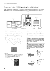
... the left click Mouse right click Click 4 Pointer • Click "Click" refers to the action of the CS1D, or use the buttons or knobs in the display to edit the setting. • Pointer The arrow shown ... use the arrow keys and ENTER key of a keyboard connected to the KEYBOARD connector of the CS1D, you wish to modify. This action is used to select the object that you can move the... in the data entry block) and dragging it up )." For a more detailed explanation of the CS1D console. Cursor Left switch Click Right switch Mouse left or right switch of the track pad (located in the...
... the left click Mouse right click Click 4 Pointer • Click "Click" refers to the action of the CS1D, or use the buttons or knobs in the display to edit the setting. • Pointer The arrow shown ... use the arrow keys and ENTER key of a keyboard connected to the KEYBOARD connector of the CS1D, you wish to modify. This action is used to select the object that you can move the... in the data entry block) and dragging it up )." For a more detailed explanation of the CS1D console. Cursor Left switch Click Right switch Mouse left or right switch of the track pad (located in the...

Owner's Manual
Page 14
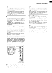
... I/O ENGINE A (DSP1D-EX{DSP1D}) ENGINE A 1 DIGITAL I/O ENGINE A 2 IN OUT CONTROL I/O CONSOLE (CS1D) DC POWER INPUT A 3 1 Digital input/output connections Use the included D-sub half pitch 68 pin cable to connect the DIGITAL I/O ENGINE A connector of the console and engine to the CONSOLE I /O OUTPUT 1 IN 5 3 1 Console (CS1D) 2 OUT 6 4 2 Engine (DSP1D-EX {DSP1D}) You must connect the identically...
... I/O ENGINE A (DSP1D-EX{DSP1D}) ENGINE A 1 DIGITAL I/O ENGINE A 2 IN OUT CONTROL I/O CONSOLE (CS1D) DC POWER INPUT A 3 1 Digital input/output connections Use the included D-sub half pitch 68 pin cable to connect the DIGITAL I/O ENGINE A connector of the console and engine to the CONSOLE I /O OUTPUT 1 IN 5 3 1 Console (CS1D) 2 OUT 6 4 2 Engine (DSP1D-EX {DSP1D}) You must connect the identically...
Owner's Manual
Page 15
..., A and B. The console and engine each other cables are used connector), the receiving device will automatically switch to the two DC POWER INPUT connectors A and B. If differently-numbered connectors are connected to each other connector. • Use only Yamaha-manufactured D-sub half pitch ... connected, connector 1 will be given priority when the power is turned on . CONSOLE CONTROL I/O ENGINE B ENGINE A 1 IN 1 IN 1 IN OUT 2 IN OUT 2 IN OUT 2 IN OUT OUT OUT Console (CS1D) MIDI IN OUT THRU CONTROL I/O CONSOLE 1 IN OUT 2 IN PC CONTROL RS-232-C OUT REMOTE RS-422 22...
..., A and B. The console and engine each other cables are used connector), the receiving device will automatically switch to the two DC POWER INPUT connectors A and B. If differently-numbered connectors are connected to each other connector. • Use only Yamaha-manufactured D-sub half pitch ... connected, connector 1 will be given priority when the power is turned on . CONSOLE CONTROL I/O ENGINE B ENGINE A 1 IN 1 IN 1 IN OUT 2 IN OUT 2 IN OUT 2 IN OUT OUT OUT Console (CS1D) MIDI IN OUT THRU CONTROL I/O CONSOLE 1 IN OUT 2 IN PC CONTROL RS-232-C OUT REMOTE RS-422 22...

Owner's Manual
Page 18
... of the console to the CONSOLE I /O 1 IN 5 • Use only Yamaha-manufactured D-sub half pitch 68 pin cables to the CONSOLE I/O connector of engine A, and the DIGITAL I/O ENGINE B connector of connection is connected. CONSOLE I/O ENGINE A 1 ENGINE B IN OUT CONTROL I/O DIGITAL I/O ENGINE A IN 2 IN OUT CONTROL I/O ENGINE B OUT CONSOLE I/O IN OUT CONTROL I/O ENGINE A (DSP1D-EX{DSP1D}) CONSOLE (CS1D) ENGINE...
... of the console to the CONSOLE I /O 1 IN 5 • Use only Yamaha-manufactured D-sub half pitch 68 pin cables to the CONSOLE I/O connector of engine A, and the DIGITAL I/O ENGINE B connector of connection is connected. CONSOLE I/O ENGINE A 1 ENGINE B IN OUT CONTROL I/O DIGITAL I/O ENGINE A IN 2 IN OUT CONTROL I/O ENGINE B OUT CONSOLE I/O IN OUT CONTROL I/O ENGINE A (DSP1D-EX{DSP1D}) CONSOLE (CS1D) ENGINE...
Owner's Manual
Page 19
...connect the DC POWER INPUT connector of the power supplies should unexpectedly fail, since the other . These connectors transmit and receive control signals between the console and engines A/B. However, you may fail to engines A/B. In order to minimize the clock switching time in a one-to the CONTROL I /O... IN PC CONTROL RS-232-C OUT REMOTE RS-422 USB GPI WORD CLOCK IN CONSOLE CONTROL I/O ENGINE B ENGINE A 1 IN 1 IN 1 IN OUT 2 IN OUT 2 IN OUT 2 IN OUT OUT OUT Console (CS1D) MIDI IN OUT THRU CONTROL I/O CONSOLE 1 IN OUT 2 IN PC CONTROL RS-232-C OUT REMOTE RS-422 USB ...
...connect the DC POWER INPUT connector of the power supplies should unexpectedly fail, since the other . These connectors transmit and receive control signals between the console and engines A/B. However, you may fail to engines A/B. In order to minimize the clock switching time in a one-to the CONTROL I /O... IN PC CONTROL RS-232-C OUT REMOTE RS-422 USB GPI WORD CLOCK IN CONSOLE CONTROL I/O ENGINE B ENGINE A 1 IN 1 IN 1 IN OUT 2 IN OUT 2 IN OUT 2 IN OUT OUT OUT Console (CS1D) MIDI IN OUT THRU CONTROL I/O CONSOLE 1 IN OUT 2 IN PC CONTROL RS-232-C OUT REMOTE RS-422 USB ...
Owner's Manual
Page 22
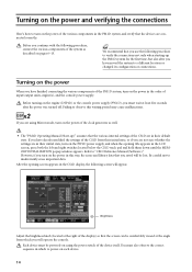
... various components of the PM1D system, turn on the power in the order of input/output units, engine(s), and the console power supply. Be careful not to "CS1D Reference Manual (Software)." Each device must be lost. Refer to inadvertently erase important data. Brightness Adjust the brightness knob ... off. Before turning on each device. 14 However, if you have moved the system to power-on the engine (DSP1D) or the console power supply (PW1D), you must also observe the correct sequence in this waiting period may cause malfunctions. Turning on pages 6-13. After ...
... various components of the PM1D system, turn on the power in the order of input/output units, engine(s), and the console power supply. Be careful not to "CS1D Reference Manual (Software)." Each device must be lost. Refer to inadvertently erase important data. Brightness Adjust the brightness knob ... off. Before turning on each device. 14 However, if you have moved the system to power-on the engine (DSP1D) or the console power supply (PW1D), you must also observe the correct sequence in this waiting period may cause malfunctions. Turning on pages 6-13. After ...
Owner's Manual
Page 23
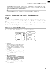
...DSPx1 After you turn on the power of the PM1D system, you can be lit. 2 CONTROL I/O If the CONTROL I/O connectors of the engine and console are connected correctly, the LED for Standard mode. Checking the engine (Standard mode) The front panel of all connected devices. ENGINE ID A B CONTROL ...that can use the LEDs and indicators of the various components to the ENGINE A or ENGINE B connectors (DIGITAL I/O, CONTROL I/ O) of the console. Please unify the software version of the DSP1D-EX {DSP1D} engine shows the following information. In Standard mode, the A LED will always be ...
...DSPx1 After you turn on the power of the PM1D system, you can be lit. 2 CONTROL I/O If the CONTROL I/O connectors of the engine and console are connected correctly, the LED for Standard mode. Checking the engine (Standard mode) The front panel of all connected devices. ENGINE ID A B CONTROL ...that can use the LEDs and indicators of the various components to the ENGINE A or ENGINE B connectors (DIGITAL I/O, CONTROL I/ O) of the console. Please unify the software version of the DSP1D-EX {DSP1D} engine shows the following information. In Standard mode, the A LED will always be ...
Owner's Manual
Page 26
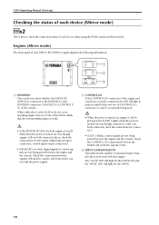
... CONFIGURATION This indicates the number of monaural input channels that can be used . • When the power is currently being passed between the console and the power supply. 2 CONTROL I/O If the CONTROL I /O connectors (1 and 2) is turned on even though engines A/B are both connected, please ... used with this engine. Check the connections between engines A/B and the console, and between the engine and the console. The "96CH" LED will light for the DSP1D-EX, and the "48CH" LED will be given priority. CS1D Operating Manual (Start-up) Checking the status of each device (Mirror mode...
... CONFIGURATION This indicates the number of monaural input channels that can be used . • When the power is currently being passed between the console and the power supply. 2 CONTROL I/O If the CONTROL I /O connectors (1 and 2) is turned on even though engines A/B are both connected, please ... used with this engine. Check the connections between engines A/B and the console, and between the engine and the console. The "96CH" LED will light for the DSP1D-EX, and the "48CH" LED will be given priority. CS1D Operating Manual (Start-up) Checking the status of each device (Mirror mode...

Owner's Manual
Page 30
... settings differ between Standard mode and Mirror mode. By pressing the same switch repeatedly, you may need to access specific functions in which one console is used to make settings again.) Be aware that function. 22 In the LED FUNCTION ACCESS block, press the [SYS/W.CLOCK] switch several times to... settings (Standard mode) DSPx1 When starting up the PM1D system for Standard mode. The PM1D system version 1.0 supports two modes: "Standard mode" in which one console is used with one engine, and "Mirror mode" in the display.
... settings differ between Standard mode and Mirror mode. By pressing the same switch repeatedly, you may need to access specific functions in which one console is used to make settings again.) Be aware that function. 22 In the LED FUNCTION ACCESS block, press the [SYS/W.CLOCK] switch several times to... settings (Standard mode) DSPx1 When starting up the PM1D system for Standard mode. The PM1D system version 1.0 supports two modes: "Standard mode" in which one console is used with one engine, and "Mirror mode" in the display.

Owner's Manual
Page 31
... the cabling within the system and the status of "OPERATION MODE." Click the button located at the right of each OUTPUT connector (1-6) of the CS1D or AO8 (in particular if an MY8-AT digital I/O card is installed in the screen shows the control signal connection, and the red line ... you will be produced from the output jacks of the engine. This indicates the type of input unit that the OPERATION MODE field indicates "CONSOLE x1 ENGINE x1." Basic settings (Standard mode) This is the SYSTEM CONNECTION screen, in which you can select the operation mode. 3. Click the button...
... the cabling within the system and the status of "OPERATION MODE." Click the button located at the right of each OUTPUT connector (1-6) of the CS1D or AO8 (in particular if an MY8-AT digital I/O card is installed in the screen shows the control signal connection, and the red line ... you will be produced from the output jacks of the engine. This indicates the type of input unit that the OPERATION MODE field indicates "CONSOLE x1 ENGINE x1." Basic settings (Standard mode) This is the SYSTEM CONNECTION screen, in which you can select the operation mode. 3. Click the button...

Owner's Manual
Page 33
... or AO8 indicator shows "UL" or the display shows a message warning that the word clock is not synchronized, check the connections between the engine and console, and the connections between the engine and the input/output units. Basic settings (Standard mode) 25 If when you must turn down the power amp... k or INT 44.1 k. When you change in the DIO8. Such a change the word clock settings, noise may be heard from the output jacks of the CS1D and AO8, particularly if an MY8-AT digital I/O card is installed in the word clock settings can select one of the following three choices as...
... or AO8 indicator shows "UL" or the display shows a message warning that the word clock is not synchronized, check the connections between the engine and console, and the connections between the engine and the input/output units. Basic settings (Standard mode) 25 If when you must turn down the power amp... k or INT 44.1 k. When you change in the DIO8. Such a change the word clock settings, noise may be heard from the output jacks of the CS1D and AO8, particularly if an MY8-AT digital I/O card is installed in the word clock settings can select one of the following three choices as...

Owner's Manual
Page 35
Click the button located at the right of each device. At this time, noise may be produced from the output jacks of the CS1D or AO8 (in particular if an MY8-AT digital I/O card is installed in the jack area to select the jack number (1 or 2) that is currently ... in the jack area to select the jack number (1 or 2) that is connected to each INPUT connector (1-10) of the number. Click the button marked "CONSOLE x 1 ENGINE x2 (Mirror Mode)." If both jacks (1/2) of the same type are connected, two lines will not be displayed instead of the power amp before...
Click the button located at the right of each device. At this time, noise may be produced from the output jacks of the CS1D or AO8 (in particular if an MY8-AT digital I/O card is installed in the jack area to select the jack number (1 or 2) that is currently ... in the jack area to select the jack number (1 or 2) that is connected to each INPUT connector (1-10) of the number. Click the button marked "CONSOLE x 1 ENGINE x2 (Mirror Mode)." If both jacks (1/2) of the same type are connected, two lines will not be displayed instead of the power amp before...
Owner's Manual
Page 36
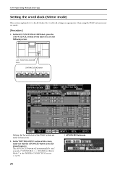
CS1D Operating Manual (Start-up) Setting the word clock (Mirror mode) This section explains how to access the following screen. In the "SETTING LEVEL" section of ... for the word clock of the screen, make sure that the ADVANCED button is on The ADVANCED button will automatically be on if you select "CONSOLE x1 ENGINE x2 (Mirror Mode)" in the SYSTEM CONNECTION screen (→p.26). 28 • ADVANCED button on (displayed in this screen. 2. In the LCD FUNCTION...
CS1D Operating Manual (Start-up) Setting the word clock (Mirror mode) This section explains how to access the following screen. In the "SETTING LEVEL" section of ... for the word clock of the screen, make sure that the ADVANCED button is on The ADVANCED button will automatically be on if you select "CONSOLE x1 ENGINE x2 (Mirror Mode)" in the SYSTEM CONNECTION screen (→p.26). 28 • ADVANCED button on (displayed in this screen. 2. In the LCD FUNCTION...
Owner's Manual
Page 37
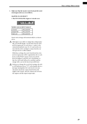
...word clock input select are set as shown above settings to each device (→refer to the connection methods on WORD CLOCK INPUT SELECT Console Engine A/B Each unit W.CLOCK IN W.CLOCK IN W.CLOCK IN Word clock settings will automatically be as follows. If when you switch ...generator to each device in the shortest possible time. MASTER CLOCK SELECT • The W.CLOCK of the engine or console is not synchronized, check the connections between the engines and console, and the connections between engines A and B in a stable manner. Make sure that the clock itself will ...
...word clock input select are set as shown above settings to each device (→refer to the connection methods on WORD CLOCK INPUT SELECT Console Engine A/B Each unit W.CLOCK IN W.CLOCK IN W.CLOCK IN Word clock settings will automatically be as follows. If when you switch ...generator to each device in the shortest possible time. MASTER CLOCK SELECT • The W.CLOCK of the engine or console is not synchronized, check the connections between the engines and console, and the connections between engines A and B in a stable manner. Make sure that the clock itself will ...

Owner's Manual
Page 38
... to the MONITOR A headphone jack) m Turn on the power in the order of input unit → DSP1D-EX {DSP1D} engine → CS1D console → monitor system m Patch the input unit to an input channel m Press the [CUE] switch of the input channel m Check whether the signal is as ...
... to the MONITOR A headphone jack) m Turn on the power in the order of input unit → DSP1D-EX {DSP1D} engine → CS1D console → monitor system m Patch the input unit to an input channel m Press the [CUE] switch of the input channel m Check whether the signal is as ...

Owner's Manual
Page 39
... malfunction due to excessive current. 31 Monitor system L R MONITOR OUT A jacks CONSOLE (CS1D) MONITOR A headphone jacks Headphones Please do not use the MONITOR A/B headphone jacks located on the top panel of the console (in the SELECTED INPUT CHANNEL block) simultaneously with the PHONES MONITOR A/B jacks located on the front panel of this is... must connect a monitor system such as powered monitor speakers or a power amp + speaker to the MONITOR OUT A jacks located on the rear panel of the CS1D console. (Since the purpose of the...
... malfunction due to excessive current. 31 Monitor system L R MONITOR OUT A jacks CONSOLE (CS1D) MONITOR A headphone jacks Headphones Please do not use the MONITOR A/B headphone jacks located on the top panel of the console (in the SELECTED INPUT CHANNEL block) simultaneously with the PHONES MONITOR A/B jacks located on the front panel of this is... must connect a monitor system such as powered monitor speakers or a power amp + speaker to the MONITOR OUT A jacks located on the rear panel of the CS1D console. (Since the purpose of the...

Owner's Manual
Page 41
... the order of the input unit to the PM1D system. LCD FUNCTION ACCESS block INPUT [PATCH] switch This is performed within the display of the CS1D console. [Procedure] 1. Checking the operation of input units Patch the input unit to an input channel Simply connecting a source to an input unit does not cause...
... the order of the input unit to the PM1D system. LCD FUNCTION ACCESS block INPUT [PATCH] switch This is performed within the display of the CS1D console. [Procedure] 1. Checking the operation of input units Patch the input unit to an input channel Simply connecting a source to an input unit does not cause...


