

Cl Editor Owner's Manual
Page 12
... window displays the mix parameters of INPUT CH 1-16, 17-32, 33-48, 49-64 (only CL3/CL5), or 65-72 (only CL5.) The parameters shown in the window can access this window in...From the [Windows] menu, choose [Overview] and select CH 1-16, 17-32, 33-48, 49-64 (only CL3/CL5), or 65-72 (only CL5) • Use the bank select keys in the window. You can be selected... the menu that will be assigned to the INPUT CH, from the fol- 1 lowing choices. 2 NONE No assignment DANTE 1-DANTE 64 DANTE INPUT 1-64 OMNI 1-OMNI 8 OMNI IN jacks 1-8 PB OUT L, PB OUT R L/R outputs of PLAYBACK SLOT1-1, SLOT1...
... window displays the mix parameters of INPUT CH 1-16, 17-32, 33-48, 49-64 (only CL3/CL5), or 65-72 (only CL5.) The parameters shown in the window can access this window in...From the [Windows] menu, choose [Overview] and select CH 1-16, 17-32, 33-48, 49-64 (only CL3/CL5), or 65-72 (only CL5) • Use the bank select keys in the window. You can be selected... the menu that will be assigned to the INPUT CH, from the fol- 1 lowing choices. 2 NONE No assignment DANTE 1-DANTE 64 DANTE INPUT 1-64 OMNI 1-OMNI 8 OMNI IN jacks 1-8 PB OUT L, PB OUT R L/R outputs of PLAYBACK SLOT1-1, SLOT1...

Cl Editor Owner's Manual
Page 17
...(B)...FX1L(A), FX8R(B) L/R inputs of EFFECT rack 1-8 PR1L(A), PR1R(B), PR2L(A), PR2R(B) L/R inputs of PREMIUM rack 1-2 DIGI L, DIGI R L/R channels of MIX channels 1-24. NONE No assignment DANTE 1-DANTE 64 DANTE OUTPUT 1-64 OMNI 1-OMNI 8 OMNI OUT jacks 1-8 3 REC L, REC R L/R inputs of RECORDER SLOT1-1, SLOT1-2...SLOT3-16 Output channels of an I/O card installed in the window...
...(B)...FX1L(A), FX8R(B) L/R inputs of EFFECT rack 1-8 PR1L(A), PR1R(B), PR2L(A), PR2R(B) L/R inputs of PREMIUM rack 1-2 DIGI L, DIGI R L/R channels of MIX channels 1-24. NONE No assignment DANTE 1-DANTE 64 DANTE OUTPUT 1-64 OMNI 1-OMNI 8 OMNI OUT jacks 1-8 3 REC L, REC R L/R inputs of RECORDER SLOT1-1, SLOT1-2...SLOT3-16 Output channels of an I/O card installed in the window...
Cl Editor Owner's Manual
Page 27
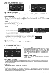
... numerical box immediately below the knob. If the ST IN is shown in the TO STEREO/MONO section. You can be displayed only if the DANTE ports have been patched. 27 CL Editor Owner's Manual You can set this to VARI-type MIX bus and MATRIX bus. ❏ TO MIX/TO...
... numerical box immediately below the knob. If the ST IN is shown in the TO STEREO/MONO section. You can be displayed only if the DANTE ports have been patched. 27 CL Editor Owner's Manual You can set this to VARI-type MIX bus and MATRIX bus. ❏ TO MIX/TO...
Cl Editor Owner's Manual
Page 35
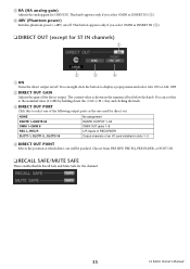
... the direct output on /off . This knob appears only if you select OMNI as INSERT IN (3). ❏ DIRECT OUT (except for direct out. NONE DANTE 1-DANTE 64 No assignment DANTE OUTPUT 1-64 OMNI 1-OMNI 8 REC L, REC R SLOT1-1, SLOT1-2...SLOT3-16 OMNI OUT jacks 1-8 L/R inputs of RECORDER Output channels of the direct output. You...
... the direct output on /off . This knob appears only if you select OMNI as INSERT IN (3). ❏ DIRECT OUT (except for direct out. NONE DANTE 1-DANTE 64 No assignment DANTE OUTPUT 1-64 OMNI 1-OMNI 8 REC L, REC R SLOT1-1, SLOT1-2...SLOT3-16 OMNI OUT jacks 1-8 L/R inputs of RECORDER Output channels of the direct output. You...
Owner's Manual
Page 7
...8226; Console firmware • Dante module firmware You must update each downloaded application. The following two types of firmware are available on a WiFi network. Introduction Details on updating the firmware are available for choosing a Yamaha CL series CL5/CL3/CL1 Digital Mixing Console. ...information about functions, effects parameters, and MIDI. Owner's Manual 7 Using the PDF manual The Reference Manual is available on the Yamaha pro audio website: http://www.yamahaproaudio.com/ Information about these benefits. Control knobs on the screen are called "buttons," and...
...8226; Console firmware • Dante module firmware You must update each downloaded application. The following two types of firmware are available on a WiFi network. Introduction Details on updating the firmware are available for choosing a Yamaha CL series CL5/CL3/CL1 Digital Mixing Console. ...information about functions, effects parameters, and MIDI. Owner's Manual 7 Using the PDF manual The Reference Manual is available on the Yamaha pro audio website: http://www.yamahaproaudio.com/ Information about these benefits. Control knobs on the screen are called "buttons," and...
Owner's Manual
Page 8
...the sonic characteristics of a large-scale sound system. CL Editor, which employs VCM technology. You can be used with Dante The Ethernet-compatible Dante audio network protocol facilitates connecting CL series consoles to DAW software installed on the CL series. 8 Owner's Manual In ...faders are moving faders. The custom fader banks enable you to select various combinations of channels, regardless of advanced concepts, including Yamaha's exclusive "CentralogicTM" control interface, which enables you to control eight channels at the highest level of the display lets you to...
...the sonic characteristics of a large-scale sound system. CL Editor, which employs VCM technology. You can be used with Dante The Ethernet-compatible Dante audio network protocol facilitates connecting CL series consoles to DAW software installed on the CL series. 8 Owner's Manual In ...faders are moving faders. The custom fader banks enable you to select various combinations of channels, regardless of advanced concepts, including Yamaha's exclusive "CentralogicTM" control interface, which enables you to control eight channels at the highest level of the display lets you to...
Owner's Manual
Page 17
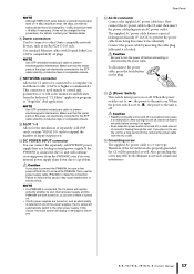
...of input/output ports. A DC POWER INPUT connector You can cause it to malfunction. Failure to observe this procedure.) For details, contact your Yamaha dealer. 8 Dante connectors Used to connect to a computer via an Ethernet cable (CAT5e or higher recommended). If you plan to connect the PW800W, be connected to.... Caution If you plan not to the unit is on , and an abnormality is connected, the CL unit will automatically switch to the other Dante-compatible network devices, such as well. When the power switch is set to , the power to use the power supply cable (PSL360) to...
...of input/output ports. A DC POWER INPUT connector You can cause it to malfunction. Failure to observe this procedure.) For details, contact your Yamaha dealer. 8 Dante connectors Used to connect to a computer via an Ethernet cable (CAT5e or higher recommended). If you plan to connect the PW800W, be connected to.... Caution If you plan not to the unit is on , and an abnormality is connected, the CL unit will automatically switch to the other Dante-compatible network devices, such as well. When the power switch is set to , the power to use the power supply cable (PSL360) to...
Owner's Manual
Page 23
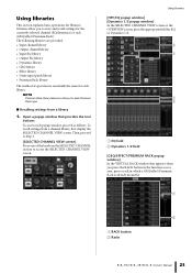
...; Input channel library • Output channel library • Input EQ library • Output EQ library • Dynamics library • GEQ library • Effect library • Dante input patch library • Premium Rack library The method of the knobs in which a GEQ/effect/Premium Rack is essentially the same for each popup...
...; Input channel library • Output channel library • Input EQ library • Output EQ library • Dynamics library • GEQ library • Effect library • Dante input patch library • Premium Rack library The method of the knobs in which a GEQ/effect/Premium Rack is essentially the same for each popup...
Owner's Manual
Page 31
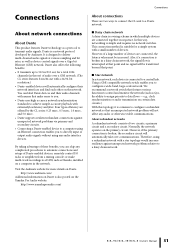
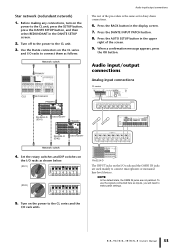
... product features Dante technology as a protocol to configure a redundant network so that an unexpected network problem will not affect any audio interface devices. Also, if a connection is simple and requires no signal will be transferred beyond that point. ■ Star network In a star network, each other on the Yamaha Pro Audio website...
... product features Dante technology as a protocol to configure a redundant network so that an unexpected network problem will not affect any audio interface devices. Also, if a connection is simple and requires no signal will be transferred beyond that point. ■ Star network In a star network, each other on the Yamaha Pro Audio website...
Owner's Manual
Page 32
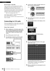
...I /O rack units. 6. When a confirmation message appears, press the OK button. EF 01 EF 01 EF012 EF012 Connections About Dante Controller Dante Controller is posted on the following website. Connecting to I/O racks This section explains how to connect the CL series to set up...4 5 6 7 8 (ID#2) 789A 3456 BCD ON 1 2 3 4 5 6 7 8 5. Set the rotary switches and DIP switches on the power to connect or set up Dante-enabled devices (such as follows: 4. Press the I /O racks. 10. Press the RACK button in the upper right of the currently-connected I /O RACK tab. 8. Press the...
...I /O rack units. 6. When a confirmation message appears, press the OK button. EF 01 EF 01 EF012 EF012 Connections About Dante Controller Dante Controller is posted on the following website. Connecting to I/O racks This section explains how to connect the CL series to set up...4 5 6 7 8 (ID#2) 789A 3456 BCD ON 1 2 3 4 5 6 7 8 5. Set the rotary switches and DIP switches on the power to connect or set up Dante-enabled devices (such as follows: 4. Press the I /O racks. 10. Press the RACK button in the upper right of the currently-connected I /O RACK tab. 8. Press the...
Owner's Manual
Page 33
Use the Dante connectors on the I /O racks to connect microphones or monaural line-level devices. Press the AUTO SETUP button in the display screen. 7. Owner's Manual 33 Turn ... procedure is the same as inputs, you will need to the CL unit, press the SETUP button, press the DANTE SETUP button, and then select REDUNDANT in the DANTE SETUP screen. 2. Press the DANTE INPUT PATCH button. 8. To use the signals connected here as for daisy chain connections. 6. Star network (redundant network) 1. Before...
Use the Dante connectors on the I /O racks to connect microphones or monaural line-level devices. Press the AUTO SETUP button in the display screen. 7. Owner's Manual 33 Turn ... procedure is the same as inputs, you will need to the CL unit, press the SETUP button, press the DANTE SETUP button, and then select REDUNDANT in the DANTE SETUP screen. 2. Press the DANTE INPUT PATCH button. 8. To use the signals connected here as for daisy chain connections. 6. Star network (redundant network) 1. Before...
Owner's Manual
Page 36
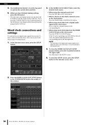
... WORD CLOCK/SLOT SETUP button in the SYSTEM SETUP field in two-channel units. 4. Setup 4. Use multifunction knobs 1-6 on the Dante network serves as the clock master Press the DANTE 48k or DANTE 44.1k button. • When using clock data from a digital audio signal as the clock source Press a valid two-channel...
... WORD CLOCK/SLOT SETUP button in the SYSTEM SETUP field in two-channel units. 4. Setup 4. Use multifunction knobs 1-6 on the Dante network serves as the clock master Press the DANTE 48k or DANTE 44.1k button. • When using clock data from a digital audio signal as the clock source Press a valid two-channel...
Owner's Manual
Page 40
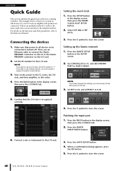
...Set the ID number for the I /O rack. 3. Confirm that power to all devices to each device. 3. Press the X symbol to the Reference Manual. Press the DANTE INPUT PATCH button. 6. For details on the unit. 3. Make sure that the I /O RACK tab. ➩ 5. Then, use multiple devices, you plan to "1."... use one I /O RACK tab. 2. NOTE If you must power-off . Select INT 48k or INT 44.1k. 3. Setting up the Dante network 1. Press the DANTE SETUP button in the display screen, then press the I /O rack, an amplifier and speakers are multiple methods to the I /O rack. Set...
...Set the ID number for the I /O rack. 3. Confirm that power to all devices to each device. 3. Press the X symbol to the Reference Manual. Press the DANTE INPUT PATCH button. 6. For details on the unit. 3. Make sure that the I /O RACK tab. ➩ 5. Then, use multiple devices, you plan to "1."... use one I /O RACK tab. 2. NOTE If you must power-off . Select INT 48k or INT 44.1k. 3. Setting up the Dante network 1. Press the DANTE SETUP button in the display screen, then press the I /O rack, an amplifier and speakers are multiple methods to the I /O rack. Set...
Owner's Manual
Page 53
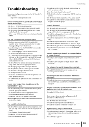
... an extreme value? ❍ Are the output channel faders raised? ❍ Check the level in the DANTE SETUP screen? Operating a fader does not control the level as the insert out? High frequency range is too... EQ attenuator raised? ❍ Could the insert be turned on even though it clicked and locked in the DANTE SETUP screen on the unit specified correctly? ❍ Is a signal being input from an externally connected recorder ... selected? ❍ Could the DIMMER be on , contact your Yamaha dealer. The unit is not receiving an input signal. ❍ Did you are posted on the...
... an extreme value? ❍ Are the output channel faders raised? ❍ Check the level in the DANTE SETUP screen? Operating a fader does not control the level as the insert out? High frequency range is too... EQ attenuator raised? ❍ Could the insert be turned on even though it clicked and locked in the DANTE SETUP screen on the unit specified correctly? ❍ Is a signal being input from an externally connected recorder ... selected? ❍ Could the DIMMER be on , contact your Yamaha dealer. The unit is not receiving an input signal. ❍ Did you are posted on the...
Owner's Manual
Page 56
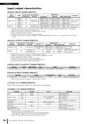
... unit is unbalanced. (Tip= LEFT, Ring= RIGHT, Sleeve= GND) *3. DIGITAL INPUT & OUTPUT CHARACTERISTICS Terminal Primary/Secondary Format Dante Data length Level 24bit or 32bit 1000Base-T Audio 64ch Input/64ch Output @48kHz Connector EtherCON Cat5e DIGITAL OUTPUT CHARACTERISTICS Terminal DIGITAL OUT... CHARACTERISTICS Each I /O CHARACTERISTICS Terminal MIDI IN OUT WORD CLOCK IN OUT GPI (5IN/5OUT) NETWORK LAMP (CL5: x3, CL3: x2, CL1: x1) USB HOST DC POWER INPUT METER (CL3/CL1 only) Format MIDI MIDI - - - All output DA converters are balanced. (1= GND, 2= HOT, 3= COLD) *3....
... unit is unbalanced. (Tip= LEFT, Ring= RIGHT, Sleeve= GND) *3. DIGITAL INPUT & OUTPUT CHARACTERISTICS Terminal Primary/Secondary Format Dante Data length Level 24bit or 32bit 1000Base-T Audio 64ch Input/64ch Output @48kHz Connector EtherCON Cat5e DIGITAL OUTPUT CHARACTERISTICS Terminal DIGITAL OUT... CHARACTERISTICS Each I /O CHARACTERISTICS Terminal MIDI IN OUT WORD CLOCK IN OUT GPI (5IN/5OUT) NETWORK LAMP (CL5: x3, CL3: x2, CL1: x1) USB HOST DC POWER INPUT METER (CL3/CL1 only) Format MIDI MIDI - - - All output DA converters are balanced. (1= GND, 2= HOT, 3= COLD) *3....
Owner's Manual
Page 59
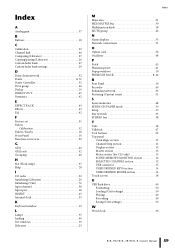
... 52 Channel link 46 Comparing (Libraries 27 Copying/pasting (Libraries 26 Custom fader bank 47 Custom fader bank settings 29 D Daisy chain network 32 Dante 8, 31 Dante Controller 32 DCA group 46 Dialog 19 DIRECT OUT 45 Dynamics 42 E EFFECT RACK 43 Effects 43 EQ 42 F Factory set 51 Faders Calibration 52...
... 52 Channel link 46 Comparing (Libraries 27 Copying/pasting (Libraries 26 Custom fader bank 47 Custom fader bank settings 29 D Daisy chain network 32 Dante 8, 31 Dante Controller 32 DCA group 46 Dialog 19 DIRECT OUT 45 Dynamics 42 E EFFECT RACK 43 Effects 43 EQ 42 F Factory set 51 Faders Calibration 52...

Owner's Manual
Page 61
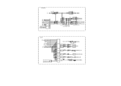
... HA METER To CASCADE IN SELECT SLOTIN SLOTIN SLOTIN METER METER METER 16 16 16 DECODER 2 PLAYBACK OUT METER GAIN To MONITOR SELECT RECORDER CUE DANTE IN 1-64 OMNI IN 1-8 To MONITOR SELECT SLOT1 1-16 CH 1-72{64,48} To RACKIN PATCH INSERT POINT To OUTPUT PATCH CH INSERT ... ON SELECT EFFECT CUE ON SELECT RECORDER CUE ON SELECT FX2-8 IN A(L)/B(R) EFFECT RACK2-8(FX2-8) (same as EFFECT RACK1) FX2-8 OUT A(L)/B(R) Refer to CL5/CL3/CL1 Mixer Block Diagram 2/2 PREMIUM RACK IN PATCH PFX1 IN A(L)/B(R) PREMIUM EFFECT RACK1(PFX1) METER RACK IN L METER RACK IN R EFFECT METER RACK OUT...
... HA METER To CASCADE IN SELECT SLOTIN SLOTIN SLOTIN METER METER METER 16 16 16 DECODER 2 PLAYBACK OUT METER GAIN To MONITOR SELECT RECORDER CUE DANTE IN 1-64 OMNI IN 1-8 To MONITOR SELECT SLOT1 1-16 CH 1-72{64,48} To RACKIN PATCH INSERT POINT To OUTPUT PATCH CH INSERT ... ON SELECT EFFECT CUE ON SELECT RECORDER CUE ON SELECT FX2-8 IN A(L)/B(R) EFFECT RACK2-8(FX2-8) (same as EFFECT RACK1) FX2-8 OUT A(L)/B(R) Refer to CL5/CL3/CL1 Mixer Block Diagram 2/2 PREMIUM RACK IN PATCH PFX1 IN A(L)/B(R) PREMIUM EFFECT RACK1(PFX1) METER RACK IN L METER RACK IN R EFFECT METER RACK OUT...
Owner's Manual
Page 62
... SLOT2 SLOT3 [PHONES] [SLOT] GAIN TRIM OUTPUT PATCH DELAY (MAX:1000ms) METER OMNI OUT DA 8 + - 2 1 [OMNI OUT] (1-8) 3 OUTPUT PATCH GAIN DELAY METER DANTE OUT (MAX:1000ms) 64 DANTE OUTPUT [DANTE OUT] (1-64) OUTPUT PATCH DELAY (MAX:1000ms) METER 2TR OUT RECORDER IN METER OUTPUT PATCH 2 GAIN GAIN TRIM DIT 2 AES/EBU [DIGITAL OUT...
... SLOT2 SLOT3 [PHONES] [SLOT] GAIN TRIM OUTPUT PATCH DELAY (MAX:1000ms) METER OMNI OUT DA 8 + - 2 1 [OMNI OUT] (1-8) 3 OUTPUT PATCH GAIN DELAY METER DANTE OUT (MAX:1000ms) 64 DANTE OUTPUT [DANTE OUT] (1-64) OUTPUT PATCH DELAY (MAX:1000ms) METER 2TR OUT RECORDER IN METER OUTPUT PATCH 2 GAIN GAIN TRIM DIT 2 AES/EBU [DIGITAL OUT...