

Cl Editor Installation Guide
Page 8
...'s Owner's Manual • Is the Network setup (IP address) of the System Setup window in the downloaded folder. If the "User Account Control" window appears, click [Continue] or [Yes]. When using Windows 7 Select [Start] [Control Panel] [Programs and Features] or [Uninstall a program], then select the application to the CL by using a LAN cable via LAN, the CL does not operate correctly. • Is the LAN cable connected correctly? Connect the...
...'s Owner's Manual • Is the Network setup (IP address) of the System Setup window in the downloaded folder. If the "User Account Control" window appears, click [Continue] or [Yes]. When using Windows 7 Select [Start] [Control Panel] [Programs and Features] or [Uninstall a program], then select the application to the CL by using a LAN cable via LAN, the CL does not operate correctly. • Is the LAN cable connected correctly? Connect the...

Cl Editor Owner's Manual
Page 5
... operations. OUTPUT NAME: Change the privileges for making mixer setup settings. GEQ 1-16: Change the operating privileges for PREMIUM rack operations. PREMIUM RACK: Change the operating privileges for GEQ (Graphic Equalizer) rack operations. E Create Creates the user key. For the specific parameters included in PROCESSING, refer to On or Off simultaneously. 9 SCENE LIST STORE/SORT: Change the operating privileges for the head amp gain (analog gain) and phantom power of the selected channel. Set All: Turn on , pressing the channel select button...
... operations. OUTPUT NAME: Change the privileges for making mixer setup settings. GEQ 1-16: Change the operating privileges for PREMIUM rack operations. PREMIUM RACK: Change the operating privileges for GEQ (Graphic Equalizer) rack operations. E Create Creates the user key. For the specific parameters included in PROCESSING, refer to On or Off simultaneously. 9 SCENE LIST STORE/SORT: Change the operating privileges for the head amp gain (analog gain) and phantom power of the selected channel. Set All: Turn on , pressing the channel select button...

Cl Editor Owner's Manual
Page 14
... operations. The button is color-coded and indicates status as follows: White: You can adjust the input level of the INPUT CH (normal mode.) Gray: INPUT CH is off switch for the signal that is sent from the INPUT CH to the LCR bus. If this knob. The numbers and alphabetical letters at the same metering point with the input channel in Meter window setup (➥ p.67.) If this channel is set...
... operations. The button is color-coded and indicates status as follows: White: You can adjust the input level of the INPUT CH (normal mode.) Gray: INPUT CH is off switch for the signal that is sent from the INPUT CH to the LCR bus. If this knob. The numbers and alphabetical letters at the same metering point with the input channel in Meter window setup (➥ p.67.) If this channel is set...
Cl Editor Owner's Manual
Page 24
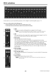
... the Channel Select/Sends On Fader checkbox in the System Setup dia- log box is not checked, the [CUE] button will be hidden in the screen. 2 ON 3 If you turn this button on the [DCA] button 1 CUE 1 This button cue-monitors all channels that displays the DCA group name. You can view and edit the parameters of DCA (Digital-Controlled Amplifier) groups 1-16. If you turn this button off, no signal will light. 5 If a DCA group...
... the Channel Select/Sends On Fader checkbox in the System Setup dia- log box is not checked, the [CUE] button will be hidden in the screen. 2 ON 3 If you turn this button on the [DCA] button 1 CUE 1 This button cue-monitors all channels that displays the DCA group name. You can view and edit the parameters of DCA (Digital-Controlled Amplifier) groups 1-16. If you turn this button off, no signal will light. 5 If a DCA group...
Cl Editor Owner's Manual
Page 72
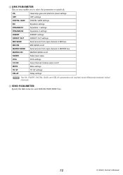
... INSERT DIRECT OUT MIX SEND MIX ON MATRIX SEND MATRIX ON FADER DCA CH ON MUTE TO ST DELAY Head amp gain and phantom power settings HPF settings DIGITAL GAIN settings Equalizer settings Dynamics 1 settings Dynamics 2 settings INSERT settings DIRECT OUT settings Send amount from input channel to interlock. 4 LINK PARAMETER This section enables you to select the parameters to MATRIX bus MATRIX SEND on/off Fader level value DCA settings Input channel module output on /off Send amount from input channel to MIX bus MIX SEND on /off Mute settings TO ST settings Delay settings NOTE The HA, FADER...
... INSERT DIRECT OUT MIX SEND MIX ON MATRIX SEND MATRIX ON FADER DCA CH ON MUTE TO ST DELAY Head amp gain and phantom power settings HPF settings DIGITAL GAIN settings Equalizer settings Dynamics 1 settings Dynamics 2 settings INSERT settings DIRECT OUT settings Send amount from input channel to interlock. 4 LINK PARAMETER This section enables you to select the parameters to MATRIX bus MATRIX SEND on/off Fader level value DCA settings Input channel module output on /off Send amount from input channel to MIX bus MIX SEND on /off Mute settings TO ST settings Delay settings NOTE The HA, FADER...

Owner's Manual
Page 2
... Connecting to I/O racks 32 Audio input/output connections 33 Installing an option card 34 Setup 35 Specifying the brightness of the touch screen, LEDs, channel name displays, and lamps 35 Setting the date and time of the internal clock 35 Word clock connections and settings 36 Making HA (Head Amp) analog gain settings ...37 Sending an input channel signal to the STEREO bus 38 Quick Guide 40 Connecting the devices 40 Setting the input channels 41 Applying EQ/dynamics 42 Setting the output channels 42 Using GEQ 42 Applying effects 43 Changing...
... Connecting to I/O racks 32 Audio input/output connections 33 Installing an option card 34 Setup 35 Specifying the brightness of the touch screen, LEDs, channel name displays, and lamps 35 Setting the date and time of the internal clock 35 Word clock connections and settings 36 Making HA (Head Amp) analog gain settings ...37 Sending an input channel signal to the STEREO bus 38 Quick Guide 40 Connecting the devices 40 Setting the input channels 41 Applying EQ/dynamics 42 Setting the output channels 42 Using GEQ 42 Applying effects 43 Changing...
Owner's Manual
Page 7
... virtual knobs are available for choosing a Yamaha CL series CL5/CL3/CL1 Digital Mixing Console. Using the PDF manual The Reference Manual is available on the Yamaha pro audio website: http://www.yamahaproaudio.com/ Information about functions, effects parameters, and MIDI. http://www.yamahaproaudio.com/ Conventions in square brackets [ ] (e.g., [CUE] key) to the firmware update guide available on a WiFi network. In addition, refer to control the unit remotely from virtual buttons and knobs displayed on the screen...
... virtual knobs are available for choosing a Yamaha CL series CL5/CL3/CL1 Digital Mixing Console. Using the PDF manual The Reference Manual is available on the Yamaha pro audio website: http://www.yamahaproaudio.com/ Information about functions, effects parameters, and MIDI. http://www.yamahaproaudio.com/ Conventions in square brackets [ ] (e.g., [CUE] key) to the firmware update guide available on a WiFi network. In addition, refer to control the unit remotely from virtual buttons and knobs displayed on the screen...
Owner's Manual
Page 8
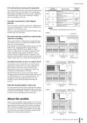
... sounds by modeling and faithfully capturing the sonic characteristics of analog sound by Rupert Neve Designs, a U76 Compressor, an Opt-2A Leveling Amplifier, etc. Effects such as custom fader banks. The currently-mounted modules can switch modules and change input/output patching in virtual racks displayed on or off -line without connecting to be routed via an intuitive graphical interface. When you recall a scene, the recorded fader locations will maintain network audio...
... sounds by modeling and faithfully capturing the sonic characteristics of analog sound by Rupert Neve Designs, a U76 Compressor, an Opt-2A Leveling Amplifier, etc. Effects such as custom fader banks. The currently-mounted modules can switch modules and change input/output patching in virtual racks displayed on or off -line without connecting to be routed via an intuitive graphical interface. When you recall a scene, the recorded fader locations will maintain network audio...
Owner's Manual
Page 9
... a USB flash drive by installing a DSP card. It also enables you to record certain bus mix outputs or play audio files that you can be stored on the screen. The MP3 format (MPEG-1 Audio Layer-3) is available in a slot. This function can use the Help function at three levels of the MIX, MATRIX, STEREO (L/R), MONO, and CUE (L/R) buses. Recorder function useful for yourself. About the models Monaural input channels Channel strips Output meters Block A: 16 CL5 72 Block B (Centralogic section): 8 Block C: 8 Yes MASTER section: 2 CL3...
... a USB flash drive by installing a DSP card. It also enables you to record certain bus mix outputs or play audio files that you can be stored on the screen. The MP3 format (MPEG-1 Audio Layer-3) is available in a slot. This function can use the Help function at three levels of the MIX, MATRIX, STEREO (L/R), MONO, and CUE (L/R) buses. Recorder function useful for yourself. About the models Monaural input channels Channel strips Output meters Block A: 16 CL5 72 Block B (Centralogic section): 8 Block C: 8 Yes MASTER section: 2 CL3...
Owner's Manual
Page 16
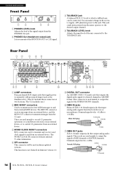
... to control CL parameters from an external device. 3 WORD CLOCK IN/OUT connectors BNC connectors used mainly to output the signals of MIX channels or MATRIX channels. These are used to transmit and receive word clock signals to and from an external device. Female XLR plug 2 (Hot) 3 (Cold) 1 (Ground) 16 Owner's Manual This jack sends instructions from the mixer operator to the desired output channel. 4 TALKBACK LEVEL knob Adjusts the input level of the mic connected to and from external MIDI devices. The WORD CLOCK IN...
... to control CL parameters from an external device. 3 WORD CLOCK IN/OUT connectors BNC connectors used mainly to output the signals of MIX channels or MATRIX channels. These are used to transmit and receive word clock signals to and from an external device. Female XLR plug 2 (Hot) 3 (Cold) 1 (Ground) 16 Owner's Manual This jack sends instructions from the mixer operator to the desired output channel. 4 TALKBACK LEVEL knob Adjusts the input level of the mic connected to and from external MIDI devices. The WORD CLOCK IN...
Owner's Manual
Page 17
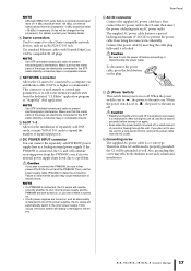
... set to , the power to malfunction. If you . Owner's Manual 17 This connector is used is on the plug. C (Power Switch) This switch turns power on , and an abnormality is off . Make sure that the metal parts of input/output ports. Therefore, if the AC outlet used mainly to control mix parameters or to other power supply. Failure to observe this procedure.) For details, contact your Yamaha dealer. 8 Dante connectors Used to connect...
... set to , the power to malfunction. If you . Owner's Manual 17 This connector is used is on the plug. C (Power Switch) This switch turns power on , and an abnormality is off . Make sure that the metal parts of input/output ports. Therefore, if the AC outlet used mainly to control mix parameters or to other power supply. Failure to observe this procedure.) For details, contact your Yamaha dealer. 8 Dante connectors Used to connect...
Owner's Manual
Page 20
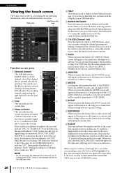
... upper part of the cue meter. During this time, the function access area of the touch screen will switch to operate and make settings for channel grouping and linking. If you can also use the faders of the top panel to the USB connector. A RECORDER When you press this button to switch to CH JOB mode, where you press part of the CUE meters when the cue monitor is accessing a USB flash drive attached to adjust the MIX/MATRIX send level...
... upper part of the cue meter. During this time, the function access area of the touch screen will switch to operate and make settings for channel grouping and linking. If you can also use the faders of the top panel to the USB connector. A RECORDER When you press this button to switch to CH JOB mode, where you press part of the CUE meters when the cue monitor is accessing a USB flash drive attached to adjust the MIX/MATRIX send level...
Owner's Manual
Page 28
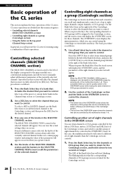
..., and hold it down for mixing using the Centralogic section's faders and keys. The OVERVIEW screen displays the main parameters, which you want to quickly switch to control. Use the controls of the selected channel. In this case, the multifunction knobs will start blinking. Press the Bank Select key for the Centralogic section. 28 Owner's Manual Operations in this case, a mini popup window indicating the value of the knobs...
..., and hold it down for mixing using the Centralogic section's faders and keys. The OVERVIEW screen displays the main parameters, which you want to quickly switch to control. Use the controls of the selected channel. In this case, the multifunction knobs will start blinking. Press the Bank Select key for the Centralogic section. 28 Owner's Manual Operations in this case, a mini popup window indicating the value of the knobs...
Owner's Manual
Page 30
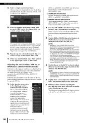
... function access area. Press the number in the display will switch to normal mode. 30 Owner's Manual Adjusting the send level to a MIX bus or MATRIX bus (SENDS ON FADER mode) Each fader on the top panel to adjust a signal that is sent from all channels that you want to monitor the signal that fader. Follow the procedure below the desired number to display the CH SELECT screen. Use the MIX or MATRIX bus select buttons in the display, press the SENDS ON FADER button...
... function access area. Press the number in the display will switch to normal mode. 30 Owner's Manual Adjusting the send level to a MIX bus or MATRIX bus (SENDS ON FADER mode) Each fader on the top panel to adjust a signal that is sent from all channels that you want to monitor the signal that fader. Follow the procedure below the desired number to display the CH SELECT screen. Use the MIX or MATRIX bus select buttons in the display, press the SENDS ON FADER button...
Owner's Manual
Page 34
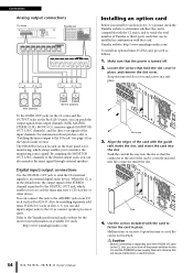
... output signals from output channels (MIX, MATRIX, STEREO (L/R), MONO (C)), monitor signals (MONITOR OUT L/R/C channels), and the direct out signals of the card is turned off the power switches for the most recent information on an I/O rack, such as follows. 1. Main speakers Monitor speakers To the OMNI OUT jacks on the CL series and the OUTPUT jacks on the front panel is in place. Caution Before connecting a separately sold mini-YGDAI I /O cards in slots 1-3, you can also monitor the same signal through external speakers...
... output signals from output channels (MIX, MATRIX, STEREO (L/R), MONO (C)), monitor signals (MONITOR OUT L/R/C channels), and the direct out signals of the card is turned off the power switches for the most recent information on an I/O rack, such as follows. 1. Main speakers Monitor speakers To the OMNI OUT jacks on the CL series and the OUTPUT jacks on the front panel is in place. Caution Before connecting a separately sold mini-YGDAI I /O cards in slots 1-3, you can also monitor the same signal through external speakers...
Owner's Manual
Page 37
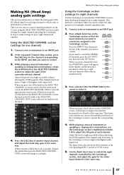
... the channel strip level meter to light at the highest audio input level. Making HA (Head Amp) analog gain settings Using the Centralogic section (settings for eight channels) Use the Centralogic section and the OVERVIEW screen to make head amp settings for up to an INPUT jack. 2. The input level is displayed around the horizontal row of knobs of the same type. Owner's Manual 37 Making HA (Head Amp) analog gain settings This section explains how to adjust...
... the channel strip level meter to light at the highest audio input level. Making HA (Head Amp) analog gain settings Using the Centralogic section (settings for eight channels) Use the Centralogic section and the OVERVIEW screen to make head amp settings for up to an INPUT jack. 2. The input level is displayed around the horizontal row of knobs of the same type. Owner's Manual 37 Making HA (Head Amp) analog gain settings This section explains how to adjust...
Owner's Manual
Page 38
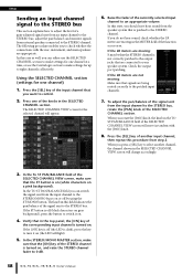
... use the SELECTED CHANNEL section to make settings for one channel) 1. Setup Sending an input channel signal to the STEREO bus This section explains how to adjust the level of a gain-adjusted signal sent from an input channel to your speaker system. If the LR meters are not moving: Make sure that the [ON] key of the STEREO channel is turned on or off (black characters on . 4. adjust the pan/balance; and monitor signals from external speakers connected to the STEREO bus...
... use the SELECTED CHANNEL section to make settings for one channel) 1. Setup Sending an input channel signal to the STEREO bus This section explains how to adjust the level of a gain-adjusted signal sent from an input channel to your speaker system. If the LR meters are not moving: Make sure that the [ON] key of the STEREO channel is turned on or off (black characters on . 4. adjust the pan/balance; and monitor signals from external speakers connected to the STEREO bus...
Owner's Manual
Page 53
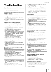
... function access area indicate MIX/MTRX ON FADER? Sound is distorted. ❍ Is the word clock set correctly? ❍ Is the GAIN of the internal head amp, external head amp, or I /O rack set to a DCA group raised? ❍ Could MUTE MASTER be turned down excessively? ❍ Are EQ's attenuators raised? The volume of a specific channel is not output from the MONITOR OUT or PHONES jack. ❍ Could a [CUE] key be applied? This problem will occur if the input signal...
... function access area indicate MIX/MTRX ON FADER? Sound is distorted. ❍ Is the word clock set correctly? ❍ Is the GAIN of the internal head amp, external head amp, or I /O rack set to a DCA group raised? ❍ Could MUTE MASTER be turned down excessively? ❍ Are EQ's attenuators raised? The volume of a specific channel is not output from the MONITOR OUT or PHONES jack. ❍ Could a [CUE] key be applied? This problem will occur if the input signal...
Owner's Manual
Page 54
.... ❍ Use the EQ attenuator function to the CL StageMix Owner's Manual on the I /O rack. ❍ Are the rotary switch and DIP switches on our web- An input signal is being controlled match the channel on ? ❍ Is the MIX bus set to the CL Editor installation guide posted on a CUE button in the SETUP screen. Signal is delayed. ❍ Check whether the delay setting for the faders to stop. ❍ Could you recall a scene, some black...
.... ❍ Use the EQ attenuator function to the CL StageMix Owner's Manual on the I /O rack. ❍ Are the rotary switch and DIP switches on our web- An input signal is being controlled match the channel on ? ❍ Is the MIX bus set to the CL Editor installation guide posted on a CUE button in the SETUP screen. Signal is delayed. ❍ Check whether the delay setting for the faders to stop. ❍ Could you recall a scene, some black...
Owner's Manual
Page 59
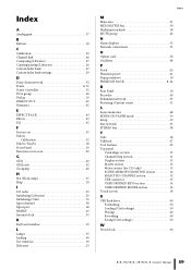
... 51 Input channel 38 Input port 40 INSERT 45 Internal clock 35 K Keyboard window 19 L Lamps 35 Linking 46 List windows 19 Llibraries 23 Index M Main area 21 MIX/MATRIX bus 30 Multifunction knob 18 MUTE group 46 N Name displays 35 Network connections 31 O Option card 34 Oscillator 48 P Patch 45 Phantom power 41 Popup windows 19 PREMIUM RACK 8, 44 R Rear Panel 16 Recorder 49 Redundant network 33 Restoring (Current scene 51 S Scene memories 48 SENDS ON FADER mode 30 Setup 35...
... 51 Input channel 38 Input port 40 INSERT 45 Internal clock 35 K Keyboard window 19 L Lamps 35 Linking 46 List windows 19 Llibraries 23 Index M Main area 21 MIX/MATRIX bus 30 Multifunction knob 18 MUTE group 46 N Name displays 35 Network connections 31 O Option card 34 Oscillator 48 P Patch 45 Phantom power 41 Popup windows 19 PREMIUM RACK 8, 44 R Rear Panel 16 Recorder 49 Redundant network 33 Restoring (Current scene 51 S Scene memories 48 SENDS ON FADER mode 30 Setup 35...


