
Owner's Manual
Page 2
...Names 43 Creating a Custom Layer by Combining Channels (User Assignable Layer) ....... 44 Using the Oscillator 45 Using the User Defined Keys 46 Using Operation Lock 47 Initializing 48 Troubleshooting 49 Error messages 51 Contents of the Reference Manual 54 Specifications 55 General Spec 55 Libraries 60 Analog Input... Output Spec 62 I/O SLOT Spec 63 MIDI/USB/WORD CLOCK I/O Spec .... 64 Dimensions 64 Options 65 Rack Mounting the 01V96i Using RK1 Rack Mount Kit 65 Index 66 01V96i Block Diagram.......End of Manual 01V96i Level Diagram .......End of Manual 01V96i-Owner's Manual
...Names 43 Creating a Custom Layer by Combining Channels (User Assignable Layer) ....... 44 Using the Oscillator 45 Using the User Defined Keys 46 Using Operation Lock 47 Initializing 48 Troubleshooting 49 Error messages 51 Contents of the Reference Manual 54 Specifications 55 General Spec 55 Libraries 60 Analog Input... Output Spec 62 I/O SLOT Spec 63 MIDI/USB/WORD CLOCK I/O Spec .... 64 Dimensions 64 Options 65 Rack Mounting the 01V96i Using RK1 Rack Mount Kit 65 Index 66 01V96i Block Diagram.......End of Manual 01V96i Level Diagram .......End of Manual 01V96i-Owner's Manual

Owner's Manual
Page 4
... all installation instructions. Lithiumbatteri-Eksplosionsfare ved fejlagtig håndtering. See user manual instructions if interference to the operation of life please consult your retailer or Yamaha representative office in your authority, granted by YAMAHA CORPORATION OF AMERICA. (class B) ADVARSEL! For disposal information in ...Ave., Buena Park, Calif. 90620 Telephone : 714-522-9011 Type of Equipment : Digital Mixing Console Model Name : 01V96i This device complies with this type of mercury. Perchlorate Material-special handling may void your country. • Gooi de ...
... all installation instructions. Lithiumbatteri-Eksplosionsfare ved fejlagtig håndtering. See user manual instructions if interference to the operation of life please consult your retailer or Yamaha representative office in your authority, granted by YAMAHA CORPORATION OF AMERICA. (class B) ADVARSEL! For disposal information in ...Ave., Buena Park, Calif. 90620 Telephone : 714-522-9011 Type of Equipment : Digital Mixing Console Model Name : 01V96i This device complies with this type of mercury. Perchlorate Material-special handling may void your country. • Gooi de ...

Owner's Manual
Page 5
...switch and disconnect the electric plug from the outlet, and have the device inspected by qualified Yamaha service personnel. • Never insert or remove an electric plug with a device that the AC outlet you mount this manual in a position where anyone could walk on it, or place it in a safe place...open the device or attempt to disassemble the internal parts or modify them in the one of the rack open • This device contains no user-serviceable parts. The power cord or plug becomes frayed or damaged. - Doing so may not be used for example by leaving space between the...
...switch and disconnect the electric plug from the outlet, and have the device inspected by qualified Yamaha service personnel. • Never insert or remove an electric plug with a device that the AC outlet you mount this manual in a position where anyone could walk on it, or place it in a safe place...open the device or attempt to disassemble the internal parts or modify them in the one of the rack open • This device contains no user-serviceable parts. The power cord or plug becomes frayed or damaged. - Doing so may not be used for example by leaving space between the...

Owner's Manual
Page 6
...from inappropriate waste handling. Maintenance • Remove the power plug from the television or radio. • Do not use . Precautions for Users on Collection and Disposal of their respective companies. Doing so may be different from the ones on the products, packaging, and/or accompanying... This device has a built-in backup battery. Always turn off when the device is lost . Yamaha cannot be mixed with moving contacts, such as shown in this Owner's Manual are the trademarks or registered trademarks of Old Equipment This symbol on your dealer or supplier for damage...
...from inappropriate waste handling. Maintenance • Remove the power plug from the television or radio. • Do not use . Precautions for Users on Collection and Disposal of their respective companies. Doing so may be different from the ones on the products, packaging, and/or accompanying... This device has a built-in backup battery. Always turn off when the device is lost . Yamaha cannot be mixed with moving contacts, such as shown in this Owner's Manual are the trademarks or registered trademarks of Old Equipment This symbol on your dealer or supplier for damage...

Owner's Manual
Page 9
... panel and the cover in order to clear the control knobs and buttons. 01V96i-Owner's Manual If you fabricate and attach your own cover and attach it to the front panel to prevent the controls from being operated inadvertently. Yamaha does not sell such a cover. Control Surface & Rear Panel Control Surface & Rear Panel... 70 40 60 70 40 60 60 70 70 50 50 50 50 50 50 50 50 50 50 50 50 50 50 50 50 USER DEFINED KEYS 1 2 3 4 5 6 7 8 1 17 AUX 1 2 18 AUX 2 3 19 AUX 3 4 20 AUX 4 5 21 AUX 5 6 22 AUX 6 7 23 AUX 7 8 24 AUX 8 9 25 BUS 1 10 26 BUS 2 11 27...
... panel and the cover in order to clear the control knobs and buttons. 01V96i-Owner's Manual If you fabricate and attach your own cover and attach it to the front panel to prevent the controls from being operated inadvertently. Yamaha does not sell such a cover. Control Surface & Rear Panel Control Surface & Rear Panel... 70 40 60 70 40 60 60 70 70 50 50 50 50 50 50 50 50 50 50 50 50 50 50 50 50 USER DEFINED KEYS 1 2 3 4 5 6 7 8 1 17 AUX 1 2 18 AUX 2 3 19 AUX 3 4 20 AUX 4 5 21 AUX 5 6 22 AUX 6 7 23 AUX 7 8 24 AUX 8 9 25 BUS 1 10 26 BUS 2 11 27...

Owner's Manual
Page 14
... gain. Holding down either key increments or decrements the selection continuously. 3 [RECALL] button This button recalls the Scene memory selected by the [SEL] button. USER DEFINED KEYS Section 1 USER DEFINED KEYS 1 2 3 4 5 6 7 8 1 [1]-[8] buttons You can assign any of the 167 functions to store or recall. 14 Control Surface & Rear Panel SELECTED CHANNEL Section... to store the current mix settings. (See page 42 for more information on Scene Memories.) 2 Scene Up [ ] / Down [ ] buttons These buttons select a Scene to these User Defined buttons. 01V96i-Owner's Manual
... gain. Holding down either key increments or decrements the selection continuously. 3 [RECALL] button This button recalls the Scene memory selected by the [SEL] button. USER DEFINED KEYS Section 1 USER DEFINED KEYS 1 2 3 4 5 6 7 8 1 [1]-[8] buttons You can assign any of the 167 functions to store or recall. 14 Control Surface & Rear Panel SELECTED CHANNEL Section... to store the current mix settings. (See page 42 for more information on Scene Memories.) 2 Scene Up [ ] / Down [ ] buttons These buttons select a Scene to these User Defined buttons. 01V96i-Owner's Manual

Owner's Manual
Page 25
... 70 40 60 70 40 60 60 70 70 50 50 50 50 50 50 50 50 50 50 50 50 50 50 50 50 USER DEFINED KEYS 1 2 3 4 5 6 7 8 PHONES jack 1 17 AUX 1 2 18 AUX 2 3 19 AUX 3 4 20 AUX 4 5 21 AUX 5 6 22 AUX 6 7 23 AUX 7 8 24 AUX 8 9 25 BUS 1 10 26 BUS... 24 analog channels can adjust the gain of the AD card channels by setting the DIP switches on the card. Connections and Setup 01V96i-Owner's Manual Connections and Setup This chapter explains how to connect and set up to external equipment, although there are numerous others. ■ Configuring an analog 16-...
... 70 40 60 70 40 60 60 70 70 50 50 50 50 50 50 50 50 50 50 50 50 50 50 50 50 USER DEFINED KEYS 1 2 3 4 5 6 7 8 PHONES jack 1 17 AUX 1 2 18 AUX 2 3 19 AUX 3 4 20 AUX 4 5 21 AUX 5 6 22 AUX 6 7 23 AUX 7 8 24 AUX 8 9 25 BUS 1 10 26 BUS... 24 analog channels can adjust the gain of the AD card channels by setting the DIP switches on the card. Connections and Setup 01V96i-Owner's Manual Connections and Setup This chapter explains how to connect and set up to external equipment, although there are numerous others. ■ Configuring an analog 16-...

Owner's Manual
Page 26
... functionality can also be used to perform locate and transport operations on the DAW, and to edit its parameters. 01V96i-Owner's Manual This allows the 01V96i to a computer-based DAW (Digital Audio Workstation). 26 Connections and Setup ■ Configuring a recording system that uses a DAW (Digital Audio Workstation) Computer TO... 70 40 60 70 40 60 60 70 70 50 50 50 50 50 50 50 50 50 50 50 50 50 50 50 50 USER DEFINED KEYS 1 2 3 4 5 6 7 8 1 17 AUX 1 2 18 AUX 2 3 19 AUX 3 4 20 AUX 4 5 21 AUX 5 6 22 AUX 6 7 23 AUX 7 8 24 AUX 8 9 25 BUS 1 10 26 BUS ...
... functionality can also be used to perform locate and transport operations on the DAW, and to edit its parameters. 01V96i-Owner's Manual This allows the 01V96i to a computer-based DAW (Digital Audio Workstation). 26 Connections and Setup ■ Configuring a recording system that uses a DAW (Digital Audio Workstation) Computer TO... 70 40 60 70 40 60 60 70 70 50 50 50 50 50 50 50 50 50 50 50 50 50 50 50 50 USER DEFINED KEYS 1 2 3 4 5 6 7 8 1 17 AUX 1 2 18 AUX 2 3 19 AUX 3 4 20 AUX 4 5 21 AUX 5 6 22 AUX 6 7 23 AUX 7 8 24 AUX 8 9 25 BUS 1 10 26 BUS ...
Owner's Manual
Page 27
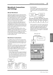
... 70 40 60 70 40 60 60 70 70 50 50 50 50 50 50 50 50 50 50 50 50 50 50 50 50 USER DEFINED KEYS 1 2 3 4 5 6 7 8 1 17 AUX 1 2 18 AUX 2 3 19 AUX 3 4 20 AUX 4 5 21 AUX 5 6 22 AUX 6 7 23 AUX 7 8 24 AUX 8 ...9 25 BUS 1 10 26 BUS 2 11 27 BUS 3 12 28 BUS 4 13 29 BUS 5 14 30 BUS 6 15 31 BUS 7 16 32 BUS 8 STEREO 01V96i-Owner's Manual Digital audio signal + Wordclock signal Digital I/O card External device CH1-4 CH5-8 CH9-12 1 2 3 4 5 6 7 8 9 10 11 12 13 15 PHANTOM +48V A A A A A A A A A A A A 14 B B B B B B B...
... 70 40 60 70 40 60 60 70 70 50 50 50 50 50 50 50 50 50 50 50 50 50 50 50 50 USER DEFINED KEYS 1 2 3 4 5 6 7 8 1 17 AUX 1 2 18 AUX 2 3 19 AUX 3 4 20 AUX 4 5 21 AUX 5 6 22 AUX 6 7 23 AUX 7 8 24 AUX 8 ...9 25 BUS 1 10 26 BUS 2 11 27 BUS 3 12 28 BUS 4 13 29 BUS 5 14 30 BUS 6 15 31 BUS 7 16 32 BUS 8 STEREO 01V96i-Owner's Manual Digital audio signal + Wordclock signal Digital I/O card External device CH1-4 CH5-8 CH9-12 1 2 3 4 5 6 7 8 9 10 11 12 13 15 PHANTOM +48V A A A A A A A A A A A A 14 B B B B B B B...

Owner's Manual
Page 44
... Select window. You can use the faders and [ON] buttons to control the assigned channels. 01V96i-Owner's Manual This custom layer is called "User Assignable layer." 1. The 01V96i displays the page shown below. 1 4. Select the channels you wish to assign in four banks by switching Banks 1-4 via the BANK 1-4...) If you set the Remote Layer target to "USER ASSIGNABLE," you can reset the assignment to default by moving the cursor to the CLEAR button and pressing [ENTER]. 5. Tip: You can create a custom layer by combining any 01V96i channels (excluding the Stereo Out). Move the cursor to...
... Select window. You can use the faders and [ON] buttons to control the assigned channels. 01V96i-Owner's Manual This custom layer is called "User Assignable layer." 1. The 01V96i displays the page shown below. 1 4. Select the channels you wish to assign in four banks by switching Banks 1-4 via the BANK 1-4...) If you set the Remote Layer target to "USER ASSIGNABLE," you can reset the assignment to default by moving the cursor to the CLEAR button and pressing [ENTER]. 5. Tip: You can create a custom layer by combining any 01V96i channels (excluding the Stereo Out). Move the cursor to...

Owner's Manual
Page 46
...recalls a specific Scene or library memory or transmits MIDI messages), an extra parameter box appears on the right and specify the number. 01V96i-Owner's Manual A function is selected, and the functions assigned to the selected buttons. 4 This page contains the following parameters: 1 INITIALIZE This ...desired banks. 3 TITLE This parameter displays the name of the 1-8 param- Follow the steps below to assign functions to USER DEFINED KEYS [1]-[8]. 4. To cancel the assignment, move the cursor to one of assignable functions. 5. If you to assign functions to the...
...recalls a specific Scene or library memory or transmits MIDI messages), an extra parameter box appears on the right and specify the number. 01V96i-Owner's Manual A function is selected, and the functions assigned to the selected buttons. 4 This page contains the following parameters: 1 INITIALIZE This ...desired banks. 3 TITLE This parameter displays the name of the 1-8 param- Follow the steps below to assign functions to USER DEFINED KEYS [1]-[8]. 4. To cancel the assignment, move the cursor to one of assignable functions. 5. If you to assign functions to the...

Owner's Manual
Page 53
... will appear if you attempt to change the output patching of a double channel when operating at 88.2 kHz or 96 kHz. Error messages 01V96i-Owner's Manual Error messages 53 Message Summary Panel operation Not assigned. This message will appear if you turn on Current Layer. If this does not solve ...Direct Out. This message will not be output because an invalid Direct Out Patch has been specified. This message will appear if you operate a user-defined key to the even-numbered channel of an output port that is assigned to Direct Out while using a remote layer whose target setting ...
... will appear if you attempt to change the output patching of a double channel when operating at 88.2 kHz or 96 kHz. Error messages 01V96i-Owner's Manual Error messages 53 Message Summary Panel operation Not assigned. This message will appear if you turn on Current Layer. If this does not solve ...Direct Out. This message will not be output because an invalid Direct Out Patch has been specified. This message will appear if you operate a user-defined key to the even-numbered channel of an output port that is assigned to Direct Out while using a remote layer whose target setting ...

Owner's Manual
Page 54
... (Bulk Dump) ....... 107 Other Functions 109 Setting Preferences 109 Creating a Custom Layer by Combining Channels (User Assignable Layer 110 Cascading Consoles 111 Checking the Battery and the System Version 113 Calibrating the Faders 113 Index 115... Patch Parameters 121 Initial Input Patch Settings 123 Output Patch Parameters 125 Initial Output Patch Settings 127 User Defined Remote Layer Initial Bank Settings 128 Effects Parameters 132 Effects and tempo synchronization 146 Preset EQ ... Table 157 MIDI Data Format 173 MIDI Implementation Chart End of Manual 01V96i-Owner's Manual
... (Bulk Dump) ....... 107 Other Functions 109 Setting Preferences 109 Creating a Custom Layer by Combining Channels (User Assignable Layer 110 Cascading Consoles 111 Checking the Battery and the System Version 113 Calibrating the Faders 113 Index 115... Patch Parameters 121 Initial Input Patch Settings 123 Output Patch Parameters 125 Initial Output Patch Settings 127 User Defined Remote Layer Initial Bank Settings 128 Effects Parameters 132 Effects and tempo synchronization 146 Preset EQ ... Table 157 MIDI Data Format 173 MIDI Implementation Chart End of Manual 01V96i-Owner's Manual

Owner's Manual
Page 60
...-42.3 s (160 points) @ 48 kHz 6 ms-46.0 s (160 points) @ 44.1 kHz 3 ms-21.1 s (160 points) @ 96 kHz 3 ms-23.0 s (160 points) @ 88.2 kHz Presets 56 User memories 72 Presets 36 User memories 92 Presets 4 User memories 124 Presets 40 User memories 160 Presets 2 User memories 127 Presets 1 User memories 32 Presets 1 User memories 32 01V96i-Owner's Manual
...-42.3 s (160 points) @ 48 kHz 6 ms-46.0 s (160 points) @ 44.1 kHz 3 ms-21.1 s (160 points) @ 96 kHz 3 ms-23.0 s (160 points) @ 88.2 kHz Presets 56 User memories 72 Presets 36 User memories 92 Presets 4 User memories 124 Presets 40 User memories 160 Presets 2 User memories 127 Presets 1 User memories 32 Presets 1 User memories 32 01V96i-Owner's Manual
Owner's Manual
Page 67
...21 TO HOST USB port 17 U USB 2.0 port 17 USB OUT 30 User Assignable Layer 44 User Define Select window 46 User Defined Keys 46 USER DEFINED KEYS Section ..........14 UTILITY button 12 Utility software 7 V VIEW button... 13 W WAVEFORM 45 WORD CLOCK IN connector 17 WORD CLOCK OUT connector .......17 Wordclock 27 Wordclock master 27 Wordclock slave 27 Wordclock Source 28 Y Yamaha Steinberg USB Driver 7 Index 67 Index 01V96i-Owner's Manual
...21 TO HOST USB port 17 U USB 2.0 port 17 USB OUT 30 User Assignable Layer 44 User Define Select window 46 User Defined Keys 46 USER DEFINED KEYS Section ..........14 UTILITY button 12 Utility software 7 V VIEW button... 13 W WAVEFORM 45 WORD CLOCK IN connector 17 WORD CLOCK OUT connector .......17 Wordclock 27 Wordclock master 27 Wordclock slave 27 Wordclock Source 28 Y Yamaha Steinberg USB Driver 7 Index 67 Index 01V96i-Owner's Manual

Reference Manual
Page 2
...(Bulk Dump) ....... 107 Other Functions 109 Setting Preferences 109 Creating a Custom Layer by Combining Channels (User Assignable Layer 110 Cascading Consoles 111 Checking the Battery and the System Version 113 Calibrating the Faders 113 Index 115... Patch Parameters 121 Initial Input Patch Settings 123 Output Patch Parameters 125 Initial Output Patch Settings 127 User Defined Remote Layer Initial Bank Settings 128 Effects Parameters 132 Effects and tempo synchronization 146 Preset EQ ...Table 157 MIDI Data Format 173 MIDI Implementation Chart End of Manual 01V96i-Reference Manual
...(Bulk Dump) ....... 107 Other Functions 109 Setting Preferences 109 Creating a Custom Layer by Combining Channels (User Assignable Layer 110 Cascading Consoles 111 Checking the Battery and the System Version 113 Calibrating the Faders 113 Index 115... Patch Parameters 121 Initial Input Patch Settings 123 Output Patch Parameters 125 Initial Output Patch Settings 127 User Defined Remote Layer Initial Bank Settings 128 Effects Parameters 132 Effects and tempo synchronization 146 Preset EQ ...Table 157 MIDI Data Format 173 MIDI Implementation Chart End of Manual 01V96i-Reference Manual
Reference Manual
Page 3
... Layer) Using the Oscillator Using the User Defined Keys Using Operation Lock Initializing Troubleshooting Error messages Contents of the separate Owner's Manual booklet are as follows. Contents of the Owner's Manual (Booklet) Contents of the Owner's Manual (Booklet) 3 Contents of the Owner's Manual (Booklet) The contents of the Reference Manual Specifications General Spec Libraries Analog Input...
... Layer) Using the Oscillator Using the User Defined Keys Using Operation Lock Initializing Troubleshooting Error messages Contents of the separate Owner's Manual booklet are as follows. Contents of the Owner's Manual (Booklet) Contents of the Owner's Manual (Booklet) 3 Contents of the Owner's Manual (Booklet) The contents of the Reference Manual Specifications General Spec Libraries Analog Input...

Reference Manual
Page 4
... CTL ASGN CONTROL CHANGE ASSIGN TABLE 104 BULK BULK DUMP 107 OSCILLATOR OSCILLATOR (45) CH STATUS CHANNEL STATUS MONITOR 14 UTILITY BATTERY BATTERY CHECK 113 USER DEF USER DEFINED KEY ASSIGN 119 LOCK OPERATION LOCK (47) PHASE PHASE 18 INSERT INSERT 47 /INSERT/ DELAY DLY 1-16 INPUT CH1-16 DELAY ... PARAMETER VIEW 31 37 24 FADER VIEW 32 38 CHANNEL LIBRARY 75 INPUT CH1-16 AUX VIEW 40 INPUT CH17-ST IN AUX VIEW 40 01V96i-Reference Manual 4 Function Tree Function Tree DISPLAY ACCESS Page numbers in parentheses ( ) are the page numbers of the Owner...
... CTL ASGN CONTROL CHANGE ASSIGN TABLE 104 BULK BULK DUMP 107 OSCILLATOR OSCILLATOR (45) CH STATUS CHANNEL STATUS MONITOR 14 UTILITY BATTERY BATTERY CHECK 113 USER DEF USER DEFINED KEY ASSIGN 119 LOCK OPERATION LOCK (47) PHASE PHASE 18 INSERT INSERT 47 /INSERT/ DELAY DLY 1-16 INPUT CH1-16 DELAY ... PARAMETER VIEW 31 37 24 FADER VIEW 32 38 CHANNEL LIBRARY 75 INPUT CH1-16 AUX VIEW 40 INPUT CH17-ST IN AUX VIEW 40 01V96i-Reference Manual 4 Function Tree Function Tree DISPLAY ACCESS Page numbers in parentheses ( ) are the page numbers of the Owner...

Reference Manual
Page 5
Function Tree FADER MODE BUTTON AUX1- AUX8 HOME (METER) FUNCTION SEND PAN VIEW1-16 VIEW17-STI CH1-32 ST IN MASTER EFFECT STEREO POSITION PAGE NAME LINK AUX1-AUX8 SEND 38 AUX1-AUX8 PAN 41 INPUT CH1-16 AUX VIEW 40 INPUT CH17-ST IN AUX VIEW 40 CH1-32 METER 8 ST IN METER 8 MASTER METER 8 EFFECT1-4 INPUT/OUTPUT METER 8 STEREO METER 8 METER POSITION 8 LAYER BUTTON 1-16 17-32 MASTER REMOTE FUNCTION USER DEFINED ProTools Nuendo Cubase General DAW USER ASSIGNABLE LAYER PAGE NAME LINK 8 8 8 94 83 93 93 94 110 Function Tree 5 01V96i-Reference Manual
Function Tree FADER MODE BUTTON AUX1- AUX8 HOME (METER) FUNCTION SEND PAN VIEW1-16 VIEW17-STI CH1-32 ST IN MASTER EFFECT STEREO POSITION PAGE NAME LINK AUX1-AUX8 SEND 38 AUX1-AUX8 PAN 41 INPUT CH1-16 AUX VIEW 40 INPUT CH17-ST IN AUX VIEW 40 CH1-32 METER 8 ST IN METER 8 MASTER METER 8 EFFECT1-4 INPUT/OUTPUT METER 8 STEREO METER 8 METER POSITION 8 LAYER BUTTON 1-16 17-32 MASTER REMOTE FUNCTION USER DEFINED ProTools Nuendo Cubase General DAW USER ASSIGNABLE LAYER PAGE NAME LINK 8 8 8 94 83 93 93 94 110 Function Tree 5 01V96i-Reference Manual

Reference Manual
Page 6
... 70 40 60 70 40 60 60 70 70 50 50 50 50 50 50 50 50 50 50 50 50 50 50 50 50 USER DEFINED KEYS 1 2 3 4 5 6 7 8 1 17 AUX 1 2 18 AUX 2 3 19 AUX 3 4 20 AUX 4 5 21 AUX 5 6 22 AUX 6 7 23 AUX 7 8 24 AUX 8 9 25 BUS 1 10 26 ...32 BUS 8 STEREO Monitor Out & Headphones Section (p. 7) SOLO Section (p. 9) Data Entry Section (p. 9) SELECTED CHANNEL Section (p. 9) ST IN Section (p. 8) Channel Strip Section (p. 7) STEREO Section (p. 8) USER DEFINED KEYS Section (p. 9) Note: For details on the function of each item, refer to "Control Surface & Rear Panel" in the Owner...
... 70 40 60 70 40 60 60 70 70 50 50 50 50 50 50 50 50 50 50 50 50 50 50 50 50 USER DEFINED KEYS 1 2 3 4 5 6 7 8 1 17 AUX 1 2 18 AUX 2 3 19 AUX 3 4 20 AUX 4 5 21 AUX 5 6 22 AUX 6 7 23 AUX 7 8 24 AUX 8 9 25 BUS 1 10 26 ...32 BUS 8 STEREO Monitor Out & Headphones Section (p. 7) SOLO Section (p. 9) Data Entry Section (p. 9) SELECTED CHANNEL Section (p. 9) ST IN Section (p. 8) Channel Strip Section (p. 7) STEREO Section (p. 8) USER DEFINED KEYS Section (p. 9) Note: For details on the function of each item, refer to "Control Surface & Rear Panel" in the Owner...


