
Owner's Manual
Page 2
...Contents 7 About the included discs 7 About the included DAW software .......... 7 About the utility software 7 Firmware updates 8 About this Owner's Manual 8 Conventions Used in this Manual 8 Control Surface & Rear Panel .......... 9 Control Surface 9 Rear Panel 16 Installing an Optional Card 18 Operating Basics 19 About the Display 19 ... Spec 62 I/O SLOT Spec 63 MIDI/USB/WORD CLOCK I/O Spec .... 64 Dimensions 64 Options 65 Rack Mounting the 01V96i Using RK1 Rack Mount Kit 65 Index 66 01V96i Block Diagram.......End of Manual 01V96i Level Diagram .......End of Manual...
...Contents 7 About the included discs 7 About the included DAW software .......... 7 About the utility software 7 Firmware updates 8 About this Owner's Manual 8 Conventions Used in this Manual 8 Control Surface & Rear Panel .......... 9 Control Surface 9 Rear Panel 16 Installing an Optional Card 18 Operating Basics 19 About the Display 19 ... Spec 62 I/O SLOT Spec 63 MIDI/USB/WORD CLOCK I/O Spec .... 64 Dimensions 64 Options 65 Rack Mounting the 01V96i Using RK1 Rack Mount Kit 65 Index 66 01V96i Block Diagram.......End of Manual 01V96i Level Diagram .......End of Manual...

Owner's Manual
Page 3
...personnel. Servicing is located on or pinched particularly at plugs, convenience receptacles, and the point where they exit from the apparatus. 11 Only use caution when moving the cart/ apparatus combination to avoid injury from being walked on the rear of the unit. • Explanation of Graphical...water. 6 Clean only with dry cloth. 7 Do not block any heat sources such as powersupply cord or plug is used, use attachments/accessories specified by the manufacturer. 12 Use only with the cart, stand, tripod, bracket, or table specified by the manufacturer, or sold with one wider than ...
...personnel. Servicing is located on or pinched particularly at plugs, convenience receptacles, and the point where they exit from the apparatus. 11 Only use caution when moving the cart/ apparatus combination to avoid injury from being walked on the rear of the unit. • Explanation of Graphical...water. 6 Clean only with dry cloth. 7 Do not block any heat sources such as powersupply cord or plug is used, use attachments/accessories specified by the manufacturer. 12 Use only with the cart, stand, tripod, bracket, or table specified by the manufacturer, or sold with one wider than ...

Owner's Manual
Page 4
... wire which is found in the USA. 3. IMPORTANT: When connecting this product to accessories and/ or another product use this product is marked by the letter E or by YAMAHA CORPORATION OF AMERICA. (Perchlorate) This product contains a high intensity lamp that may apply, See www.dtsc.ca.gov... : 6600 Orangethorpe Ave., Buena Park, Calif. 90620 Telephone : 714-522-9011 Type of Equipment : Digital Mixing Console Model Name : 01V96i This device complies with the coloured markings identifying the terminals in the United States, refer to the Electronic Industries Alliance web site: www.eiae...
... wire which is found in the USA. 3. IMPORTANT: When connecting this product to accessories and/ or another product use this product is marked by the letter E or by YAMAHA CORPORATION OF AMERICA. (Perchlorate) This product contains a high intensity lamp that may apply, See www.dtsc.ca.gov... : 6600 Orangethorpe Ave., Buena Park, Calif. 90620 Telephone : 714-522-9011 Type of Equipment : Digital Mixing Console Model Name : 01V96i This device complies with the coloured markings identifying the terminals in the United States, refer to the Electronic Industries Alliance web site: www.eiae...

Owner's Manual
Page 5
... the device in a position where anyone could walk on, trip over, or roll anything over it. • Only use immediately and have the device inspected by qualified Yamaha service personnel. • Never insert or remove an electric plug with the wall and detach from the power cord, resulting...wet conditions, or place on its side or upside down. Then have the device inspected by Yamaha service personnel. - If you intend to avoid the possibility of physical injury to you are not using is easily accessible. It emits unusual smells or smoke. - These precautions include, but are...
... the device in a position where anyone could walk on, trip over, or roll anything over it. • Only use immediately and have the device inspected by qualified Yamaha service personnel. • Never insert or remove an electric plug with the wall and detach from the power cord, resulting...wet conditions, or place on its side or upside down. Then have the device inspected by Yamaha service personnel. - If you intend to avoid the possibility of physical injury to you are not using is easily accessible. It emits unusual smells or smoke. - These precautions include, but are...

Owner's Manual
Page 6
... Owner's Manual are the trademarks or registered trademarks of this device or from the television or radio. • Do not use . Consult qualified Yamaha service personnel about collection and recycling of old products, please contact your local municipality, your waste disposal service or the point...your weight on the device or place heavy objects on it, and avoid use or modifications to the device, or data that used electrical and electronic products should not be discolored or disfigured. Yamaha cannot be lost or destroyed. Connections • Before connecting the device to...
... Owner's Manual are the trademarks or registered trademarks of this device or from the television or radio. • Do not use . Consult qualified Yamaha service personnel about collection and recycling of old products, please contact your local municipality, your waste disposal service or the point...your weight on the device or place heavy objects on it, and avoid use or modifications to the device, or data that used electrical and electronic products should not be discolored or disfigured. Yamaha cannot be lost or destroyed. Connections • Before connecting the device to...
Owner's Manual
Page 7
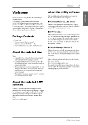
...the above website and to your computer will allow audio/MIDI communication to make settings for choosing the Yamaha 01V96i Digital Mixing Console. About the included DAW software Yamaha Corporation provides no responsibility for the included DAW software. It also allows you to back up the ... may result from the use it in a conventional audio player. Installing it in your computer. The 01V96i covers a broad range of the latest updates, and a FAQ. About the utility software The provided utility software allows you for the 01V96i console from the Yamaha Pro Audio website. http...
...the above website and to your computer will allow audio/MIDI communication to make settings for choosing the Yamaha 01V96i Digital Mixing Console. About the included DAW software Yamaha Corporation provides no responsibility for the included DAW software. It also allows you to back up the ... may result from the use it in a conventional audio player. Installing it in your computer. The 01V96i covers a broad range of the latest updates, and a FAQ. About the utility software The provided utility software allows you for the 01V96i console from the Yamaha Pro Audio website. http...
Owner's Manual
Page 8
...possibilities. In order to the firmware update guide provided on the website. You can select display pages by using "Adobe®Reader®" to view this Manual The 01V96i features two types of the functionality, the effect parameters, and MIDI-related functions. http://www.adobe.com.... References to physical buttons are performed with the product connected to a computer, so you must first install the "Yamaha Steinberg USB Driver" in your computer. Using the PDF manual The reference manual is provided as a PDF-format electronic file that appear on the display pages. ...
...possibilities. In order to the firmware update guide provided on the website. You can select display pages by using "Adobe®Reader®" to view this Manual The 01V96i features two types of the functionality, the effect parameters, and MIDI-related functions. http://www.adobe.com.... References to physical buttons are performed with the product connected to a computer, so you must first install the "Yamaha Steinberg USB Driver" in your computer. Using the PDF manual The reference manual is provided as a PDF-format electronic file that appear on the display pages. ...
Owner's Manual
Page 10
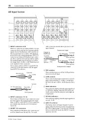
...-16 -60 GAIN +4 GAIN -26 +4 GAIN -26 PEAK SIGNAL 13 PEAK SIGNAL 14 15 PEAK SIGNAL 16 2 8 1 INPUT connectors A/B INPUT A connectors are selected. 01V96i-Owner's Manual Male XLR plug 1 (ground) 3 (cold) 2 (hot) 1/4" TRS phone plug Tip (hot) Ring (cold) Sleeve (ground) 2 INPUT connectors 13-16... These balanced TRS phone-type connectors accept line-level signals. The nominal signal level ranges from -26 dB to AD input channels. Use a split cable to insert an external effects processor to +4 dB. When the button is effective. Connect to the corresponding input. Input ...
...-16 -60 GAIN +4 GAIN -26 +4 GAIN -26 PEAK SIGNAL 13 PEAK SIGNAL 14 15 PEAK SIGNAL 16 2 8 1 INPUT connectors A/B INPUT A connectors are selected. 01V96i-Owner's Manual Male XLR plug 1 (ground) 3 (cold) 2 (hot) 1/4" TRS phone plug Tip (hot) Ring (cold) Sleeve (ground) 2 INPUT connectors 13-16... These balanced TRS phone-type connectors accept line-level signals. The nominal signal level ranges from -26 dB to AD input channels. Use a split cable to insert an external effects processor to +4 dB. When the button is effective. Connect to the corresponding input. Input ...

Owner's Manual
Page 11
... These buttons also allow you can connect a set of the Stereo Out. 1 SEL 2 ON 0 5 10 15 20 30 40 50 60 70 3 STEREO 01V96i-Owner's Manual The [ON] button indicators for the currently-selected channel lights 3 up. Control Surface & Rear Panel Control Surface 11 Monitor Out & Headphones Section ...0 LEVEL10 MONITOR OUT 0 LEVEL10 PHONES 5 4 1 2TR IN/OUT connectors These unbalanced RCA phono connectors input and output line-level signals, and are typically used to 1 select desired channels. nels light up . 4 15 30 20 40 30 50 40 60 70 50 3 [ON] buttons 1 17 AUX 1...
... These buttons also allow you can connect a set of the Stereo Out. 1 SEL 2 ON 0 5 10 15 20 30 40 50 60 70 3 STEREO 01V96i-Owner's Manual The [ON] button indicators for the currently-selected channel lights 3 up. Control Surface & Rear Panel Control Surface 11 Monitor Out & Headphones Section ...0 LEVEL10 MONITOR OUT 0 LEVEL10 PHONES 5 4 1 2TR IN/OUT connectors These unbalanced RCA phono connectors input and output line-level signals, and are typically used to 1 select desired channels. nels light up . 4 15 30 20 40 30 50 40 60 70 50 3 [ON] buttons 1 17 AUX 1...

Owner's Manual
Page 12
... of these buttons switches the Fader mode (see page 22), and displays the corresponding Aux page. (The selected button's indicator lights up the 01V96i, including digital input and output setup and remote control setup. 3 [MIDI] button This button displays a MIDI page, enabling you to make... MIDI settings. 4 [UTILITY] button This button displays a Utility page, enabling you to use the internal oscillators and view information about installed optional cards. 5 [ /INSERT/DELAY] button This button displays a /INS/DLY page, enabling you to...
... of these buttons switches the Fader mode (see page 22), and displays the corresponding Aux page. (The selected button's indicator lights up the 01V96i, including digital input and output setup and remote control setup. 3 [MIDI] button This button displays a MIDI page, enabling you to make... MIDI settings. 4 [UTILITY] button This button displays a Utility page, enabling you to use the internal oscillators and view information about installed optional cards. 5 [ /INSERT/DELAY] button This button displays a /INS/DLY page, enabling you to...

Owner's Manual
Page 13
...[F1]-[F4] buttons These buttons select a page from a multi-page screen. A [EFFECT] button This button displays an Effect page, enabling you can use optional plug-in the Channel Strip section. You can control Channels 1-16. B [VIEW] button This button displays a View page, enabling you to set...to control external MIDI devices or computer-based DAWs. Selecting a tab at the bottom of the screen using one of these buttons to display the additional tabs. Tab Scroll arrow 01V96i-Owner's Manual Control Surface & Rear Panel Control Surface 13 0 [EQ] button This button displays an...
...[F1]-[F4] buttons These buttons select a page from a multi-page screen. A [EFFECT] button This button displays an Effect page, enabling you can use optional plug-in the Channel Strip section. You can control Channels 1-16. B [VIEW] button This button displays a View page, enabling you to set...to control external MIDI devices or computer-based DAWs. Selecting a tab at the bottom of the screen using one of these buttons to display the additional tabs. Tab Scroll arrow 01V96i-Owner's Manual Control Surface & Rear Panel Control Surface 13 0 [EQ] button This button displays an...
Owner's Manual
Page 16
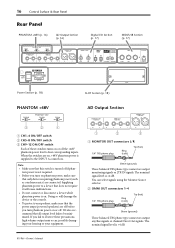
Note: • Make sure that this switch is +4 dB. 01V96i-Owner's Manual The nominal signal level is turned off if phan- tom power is on or off the +48V phantom power feed to a device that ... turn on or off. We also recommend that all output level faders be minimized. Supplying phantom power to four corresponding inputs. You can select signals using the Monitor Source selector. 2 OMNI OUT connectors 1-4 1/4" TRS phone plug Ring (cold) Tip (hot) Sleeve (ground) These balanced TRS phone-type connectors output any Bus...
Note: • Make sure that this switch is +4 dB. 01V96i-Owner's Manual The nominal signal level is turned off if phan- tom power is on or off the +48V phantom power feed to a device that ... turn on or off. We also recommend that all output level faders be minimized. Supplying phantom power to four corresponding inputs. You can select signals using the Monitor Source selector. 2 OMNI OUT connectors 1-4 1/4" TRS phone plug Ring (cold) Tip (hot) Sleeve (ground) These balanced TRS phone-type connectors output any Bus...
Owner's Manual
Page 17
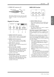
...2 TO HOST USB port This USB port enables you must do the following measures. The connector is +4 dB. Note when using the TO HOST USB port When connecting the 01V96i to a computer via the TO HOST USB port, please take these measures, your computer. • Connect the TO HOST...stops operating, turn the power off and on /off and on, or between disconnecting and reconnecting the USB cable. 01V96i-Owner's Manual The nominal signal level is typically used to the 01V96i. 3 ADAT IN/OUT connectors These optical connectors input and output ADAT digital audio signals. 4 2TR OUT DIGITAL ...
...2 TO HOST USB port This USB port enables you must do the following measures. The connector is +4 dB. Note when using the TO HOST USB port When connecting the 01V96i to a computer via the TO HOST USB port, please take these measures, your computer. • Connect the TO HOST...stops operating, turn the power off and on /off and on, or between disconnecting and reconnecting the USB cable. 01V96i-Owner's Manual The nominal signal level is typically used to the 01V96i. 3 ADAT IN/OUT connectors These optical connectors input and output ADAT digital audio signals. 4 2TR OUT DIGITAL ...
Owner's Manual
Page 18
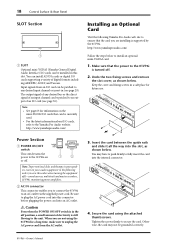
... Audio web site to ensure that can be currently used. • For the latest information about I/O cards, refer to the Yamaha Pro Audio website. Caution Even when the POWER ON/OFF switch is in the off )-sound sources, multitrack and master recorders, 01V96i, monitoring power amplifiers. 2 AC IN connector This connector enables you...
... Audio web site to ensure that can be currently used. • For the latest information about I/O cards, refer to the Yamaha Pro Audio website. Caution Even when the POWER ON/OFF switch is in the off )-sound sources, multitrack and master recorders, 01V96i, monitoring power amplifiers. 2 AC IN connector This connector enables you...

Owner's Manual
Page 19
...corresponding [SEL] button. The display indicates the following items: 2 1 3 4 567 8 0 9 A B C 5 MIDI indicator This indicator appears when the 01V96i is write-protected, a padlock icon ( ) appears. 4 EDIT indicator This indicator appears when the current mix settings no longer match those of the currently-selected Scene... indicates various parameters that you must set before you can edit the short name if you to use the display and operate the controls on the 01V96i, including how to select a display page. Operating Basics Operating Basics 19 Operating Basics This chapter ...
...corresponding [SEL] button. The display indicates the following items: 2 1 3 4 567 8 0 9 A B C 5 MIDI indicator This indicator appears when the 01V96i is write-protected, a padlock icon ( ) appears. 4 EDIT indicator This indicator appears when the current mix settings no longer match those of the currently-selected Scene... indicates various parameters that you must set before you can edit the short name if you to use the display and operate the controls on the 01V96i, including how to select a display page. Operating Basics Operating Basics 19 Operating Basics This chapter ...

Owner's Manual
Page 20
...F1]-[F4] buttons below the corresponding tab to use the display interface. If display page groups contain more than four pages, either the Left or Right [ ]/[ ] Tab Scroll button (depending on the top panel to the previous page group, the 01V96i displays the correct page, with the same parameter... If you to select a page that have cur- You can change the value. Press the corresponding button on where the page is cancelled. 01V96i-Owner's Manual You can select pages that has a hidden tab. • To select the first page in the group: Double-click the ...
...F1]-[F4] buttons below the corresponding tab to use the display interface. If display page groups contain more than four pages, either the Left or Right [ ]/[ ] Tab Scroll button (depending on the top panel to the previous page group, the 01V96i displays the correct page, with the same parameter... If you to select a page that have cur- You can change the value. Press the corresponding button on where the page is cancelled. 01V96i-Owner's Manual You can select pages that has a hidden tab. • To select the first page in the group: Double-click the ...

Owner's Manual
Page 21
...the selected target. [MASTER] button Master Layer Aux Send masters 1-8 Bus Out masters 1-8 Tip: • The function of the Layer settings. 01V96i-Owner's Manual To insert a space at the cursor position and move subsequent characters to the DEL button and press [ENTER]. To delete the ...illustrated below. Selecting Layers Input Channels and Output Channels (Bus Outs & Aux Outs) are four layers altogether. If you can access using the LAYER buttons, and the parameters you take no action for awhile, the confirmation window closes automatically and the function is entered. To...
...the selected target. [MASTER] button Master Layer Aux Send masters 1-8 Bus Out masters 1-8 Tip: • The function of the Layer settings. 01V96i-Owner's Manual To insert a space at the cursor position and move subsequent characters to the DEL button and press [ENTER]. To delete the ...illustrated below. Selecting Layers Input Channels and Output Channels (Bus Outs & Aux Outs) are four layers altogether. If you can access using the LAYER buttons, and the parameters you take no action for awhile, the confirmation window closes automatically and the function is entered. To...

Owner's Manual
Page 22
... select a channel on pages that cover multiple channels, press the corresponding [SEL] button. To select a channel on the 01V96i, press the corresponding [SEL] button. Use the corresponding [SEL] button to that includes the desired channel (see page 21). 2. REO [SEL] button. If the...layer that does contain such a parameter is selected. The following Fader modes: • When the [HOME] button indicator lights up . 01V96i-Owner's Manual Press the FADER MODE buttons to that does contain such a parameter is lit, the indicator automatically turns off and the [HOME...
... select a channel on pages that cover multiple channels, press the corresponding [SEL] button. To select a channel on the 01V96i, press the corresponding [SEL] button. Use the corresponding [SEL] button to that includes the desired channel (see page 21). 2. REO [SEL] button. If the...layer that does contain such a parameter is selected. The following Fader modes: • When the [HOME] button indicator lights up . 01V96i-Owner's Manual Press the FADER MODE buttons to that does contain such a parameter is lit, the indicator automatically turns off and the [HOME...

Owner's Manual
Page 23
Move the cursor to check Input and Output Channel levels using the Meter pages. 1. ter button in each section. • PRE EQ Immediately before EQ. • PRE FADER ........Immediately before the fader. • POST FADER.....Immediately ... left and right ST IN Channel 1-4 levels separately. • Master page This section displays the Output Channel (Aux Out 1-8, Bus Out 1-8, Stereo Out) levels altogether. 01V96i-Owner's Manual This page enables you to set the metering position for Output Channel (Aux Out 1-8, Bus Out 1-8, Stereo Out) signals. 2. Press the FADER MODE...
Move the cursor to check Input and Output Channel levels using the Meter pages. 1. ter button in each section. • PRE EQ Immediately before EQ. • PRE FADER ........Immediately before the fader. • POST FADER.....Immediately ... left and right ST IN Channel 1-4 levels separately. • Master page This section displays the Output Channel (Aux Out 1-8, Bus Out 1-8, Stereo Out) levels altogether. 01V96i-Owner's Manual This page enables you to set the metering position for Output Channel (Aux Out 1-8, Bus Out 1-8, Stereo Out) signals. 2. Press the FADER MODE...

Owner's Manual
Page 24
To cancel the Peak Hold function, turn the PEAK HOLD button off. 01V96i-Owner's Manual If you selected the CH1-32 page or the Master page, use the MASTER MODE parameter to select one of the following three metering signal types: • GATE GR The amount of gain reduction for the gate (.... • Stereo page This page displays the Stereo Out output level. To activate the Peak Hold function, move the cursor to change the metering position using the POSITION parameter. This parameter setting operates in unison with the Meter | Position page setting. 4.
To cancel the Peak Hold function, turn the PEAK HOLD button off. 01V96i-Owner's Manual If you selected the CH1-32 page or the Master page, use the MASTER MODE parameter to select one of the following three metering signal types: • GATE GR The amount of gain reduction for the gate (.... • Stereo page This page displays the Stereo Out output level. To activate the Peak Hold function, move the cursor to change the metering position using the POSITION parameter. This parameter setting operates in unison with the Meter | Position page setting. 4.


