
Owner's Manual
Page 9
... 147 Using Fader Groups and Mute Groups 148 Linking EQ and Compressor Parameters 150 14 Internal Effects 153 About the Internal Effects 153 Using Effects Processors via Aux Sends 154 Inserting the Internal Effects into Channels 156 Editing Effects 157 About Plug-Ins 159 15 Scene Memories 161 About Scene Memories 161 What is Stored... Remote Function 185 Pro Tools Remote Layer 186 Nuendo Remote Layer 202 Other DAW Remote Layers 202 MIDI Remote Layer 203 Machine Control Function 208 01V96-Owner's Manual
... 147 Using Fader Groups and Mute Groups 148 Linking EQ and Compressor Parameters 150 14 Internal Effects 153 About the Internal Effects 153 Using Effects Processors via Aux Sends 154 Inserting the Internal Effects into Channels 156 Editing Effects 157 About Plug-Ins 159 15 Scene Memories 161 About Scene Memories 161 What is Stored... Remote Function 185 Pro Tools Remote Layer 186 Nuendo Remote Layer 202 Other DAW Remote Layers 202 MIDI Remote Layer 203 Machine Control Function 208 01V96-Owner's Manual
Owner's Manual
Page 10
...the User Defined Keys 231 Using Operation Lock 233 Cascading Consoles 234 Checking the Battery and the System Version 238 Initializing the 01V96 239 Calibrating the Faders 240 Appendix A: Parameter Lists 241 USER DEFINED KEYS 241 USER DEFINED KEYS Initial Assignments 243 Input Patch...Parameters 243 Initial Input Patch Settings 245 Output Patch Parameters 247 Initial Output Patch Settings 249 User Defined Remote Layer Initial Bank Settings 250 Effects Parameters 254 Preset EQ Parameters 274 Preset Gate Parameters (fs = 44.1 kHz 278 Preset Compressor Parameters (fs = 44.1 kHz 278...
...the User Defined Keys 231 Using Operation Lock 233 Cascading Consoles 234 Checking the Battery and the System Version 238 Initializing the 01V96 239 Calibrating the Faders 240 Appendix A: Parameter Lists 241 USER DEFINED KEYS 241 USER DEFINED KEYS Initial Assignments 243 Input Patch...Parameters 243 Initial Input Patch Settings 245 Output Patch Parameters 247 Initial Output Patch Settings 249 User Defined Remote Layer Initial Bank Settings 250 Effects Parameters 254 Preset EQ Parameters 274 Preset Gate Parameters (fs = 44.1 kHz 278 Preset Compressor Parameters (fs = 44.1 kHz 278...
Owner's Manual
Page 12
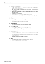
...channel surround sound production • Surround channel outputs can be stored in libraries and recalled. ■ Effects • Four high-quality multi-channel effects (Apply effects via MIDI 01V96-Owner's Manual Group multiple channels and pair channels for each Input Channel and Output Channel • Four... for computer connection • Scene recall and mix parameter changes via Aux Sends or Channel Inserts) • Effect library for storing and recalling effect settings. ■ Scene Memory • Scene memories for storing and recalling mix settings as Group Buses. &#...
...channel surround sound production • Surround channel outputs can be stored in libraries and recalled. ■ Effects • Four high-quality multi-channel effects (Apply effects via MIDI 01V96-Owner's Manual Group multiple channels and pair channels for each Input Channel and Output Channel • Four... for computer connection • Scene recall and mix parameter changes via Aux Sends or Channel Inserts) • Effect library for storing and recalling effect settings. ■ Scene Memory • Scene memories for storing and recalling mix settings as Group Buses. &#...
Owner's Manual
Page 13
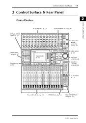
... DISPLAY ACCESS SCENE MEMORY FADER MODE Section (p. 17) LAYER Section (p. 19) SCENE DIO/SETUP MIDI UTILITY / INSERT/ PAN/ PAIR/ DELAY ROUTING GROUP PATCH DYNAMICS EQ EFFECT FADER MODE VIEW AUX 1 AUX 2 AUX 3 AUX 4 AUX 5 AUX 6 AUX 7 AUX 8 HOME (METER) LAYER 1-16 17-32 MASTER REMOTE Display Section (p. 19) OVER 0 -3 -6 -9 -12 -15... (p. 22) Data Entry Section (p. 22) SELECTED CHANNEL Section (p. 20) ST IN Section (p. 17) Channel Strip Section (p. 16) STEREO Section (p. 16) USER DEFINED KEYS Section (p. 21) 01V96-Owner's Manual
... DISPLAY ACCESS SCENE MEMORY FADER MODE Section (p. 17) LAYER Section (p. 19) SCENE DIO/SETUP MIDI UTILITY / INSERT/ PAN/ PAIR/ DELAY ROUTING GROUP PATCH DYNAMICS EQ EFFECT FADER MODE VIEW AUX 1 AUX 2 AUX 3 AUX 4 AUX 5 AUX 6 AUX 7 AUX 8 HOME (METER) LAYER 1-16 17-32 MASTER REMOTE Display Section (p. 19) OVER 0 -3 -6 -9 -12 -15... (p. 22) Data Entry Section (p. 22) SELECTED CHANNEL Section (p. 20) ST IN Section (p. 17) Channel Strip Section (p. 16) STEREO Section (p. 16) USER DEFINED KEYS Section (p. 21) 01V96-Owner's Manual
Owner's Manual
Page 14
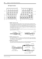
... is not supplied to INSERT jack To processor's input 1/4" phone plug Sleeve (ground) Tip (return) Sleeve (ground) From processor's output 01V96-Owner's Manual INPUT B connectors are balanced XLR-3-31-type connectors that accept line-level and microphone signals. Phantom power is turned off the ...feed to the corresponding input. INPUT 15 & 16 connectors are used for channel insert ins and outs. Use a split cable to insert an external effects processor to AD input channels. 1/4" phone plug Tip (send) Tip (send) Ring (return) 1/4" phone plug Sleeve (ground) Connect to these ...
... is not supplied to INSERT jack To processor's input 1/4" phone plug Sleeve (ground) Tip (return) Sleeve (ground) From processor's output 01V96-Owner's Manual INPUT B connectors are balanced XLR-3-31-type connectors that accept line-level and microphone signals. Phantom power is turned off the ...feed to the corresponding input. INPUT 15 & 16 connectors are used for channel insert ins and outs. Use a split cable to insert an external effects processor to AD input channels. 1/4" phone plug Tip (send) Tip (send) Ring (return) 1/4" phone plug Sleeve (ground) Connect to these ...
Owner's Manual
Page 18
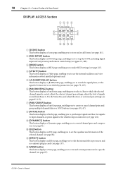
... delay parameters (see pages 79, 127). D [UTILITY] button This button displays a Utility page, enabling you to edit the internal effects processors and use the internal oscillators and view information about installed optional cards. C [MIDI] button This button displays a MIDI page, enabling...SCENE DIO/SETUP MIDI UTILITY / INSERT/ PAN/ PAIR/ DELAY ROUTING GROUP PATCH DYNAMICS EQ EFFECT VIEW 7 8 9JKL A [SCENE] button This button displays a Scene page, enabling you to view and set up the 01V96, including digital input and output setup and remote control setup (see pgaes 72, 188)....
... delay parameters (see pages 79, 127). D [UTILITY] button This button displays a Utility page, enabling you to edit the internal effects processors and use the internal oscillators and view information about installed optional cards. C [MIDI] button This button displays a MIDI page, enabling...SCENE DIO/SETUP MIDI UTILITY / INSERT/ PAN/ PAIR/ DELAY ROUTING GROUP PATCH DYNAMICS EQ EFFECT VIEW 7 8 9JKL A [SCENE] button This button displays a Scene page, enabling you to view and set up the 01V96, including digital input and output setup and remote control setup (see pgaes 72, 188)....

Owner's Manual
Page 29
...[ENTER] button to confirm the change in this type of multiple options. If you return to the previous page group, the 01V96 displays the correct page, with the same parameter selected. You can change the value. The buttons also enable you can also select a... the cursor to the appropriate button, then press the [ENTER] button to adjust the continuously variable parameter values, including Input Channel levels and effects parameters. Operating Basics Rotary Controls & Faders The rotary controls and faders enable you select a new page group. Press the cursor buttons to ...
...[ENTER] button to confirm the change in this type of multiple options. If you return to the previous page group, the 01V96 displays the correct page, with the same parameter selected. You can change the value. The buttons also enable you can also select a... the cursor to the appropriate button, then press the [ENTER] button to adjust the continuously variable parameter values, including Input Channel levels and effects parameters. Operating Basics Rotary Controls & Faders The rotary controls and faders enable you select a new page group. Press the cursor buttons to ...

Owner's Manual
Page 35
Effect page This page displays the internal effects processor 1-4 input and output levels altogether. 01V96-Owner's Manual Metering 35 - ST IN page This page displays the left and right ST IN Channel 1-4 levels separately. 3 Operating Basics - Master page This section displays the Output Channel (Aux Out 1-8, Bus Out 1-8, Stereo Out) levels altogether. -
Effect page This page displays the internal effects processor 1-4 input and output levels altogether. 01V96-Owner's Manual Metering 35 - ST IN page This page displays the left and right ST IN Channel 1-4 levels separately. 3 Operating Basics - Master page This section displays the Output Channel (Aux Out 1-8, Bus Out 1-8, Stereo Out) levels altogether. -
Owner's Manual
Page 37
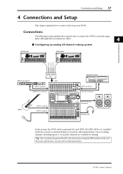
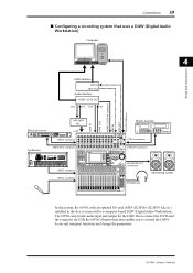
... 15 PEAK SIGNAL 16 0 10 LEVEL PHONES DISPLAY ACCESS SCENE MEMORY SCENE DIO/SETUP MIDI UTILITY / INSERT/ PAN/ PAIR/ DELAY ROUTING GROUP PATCH DYNAMICS EQ EFFECT FADER MODE VIEW AUX 1 AUX 2 AUX 3 AUX 4 AUX 5 AUX 6 AUX 7 AUX 8 HOME (METER) LAYER 1-16 17-32 MASTER REMOTE OVER 0 -3 -6 -9 -12 -15 -18 ...12 28 BUS 4 13 29 BUS 5 14 30 BUS 6 15 31 BUS 7 16 32 BUS 8 STEREO VOL VOL Monitoring system In this system, the 01V96, with an optional AD card (MY8-AD, MY8-AD96, etc.) installed in System 4 Connections and Setup MY8-AD96 etc. Up to 24 analog channels, including...
... 15 PEAK SIGNAL 16 0 10 LEVEL PHONES DISPLAY ACCESS SCENE MEMORY SCENE DIO/SETUP MIDI UTILITY / INSERT/ PAN/ PAIR/ DELAY ROUTING GROUP PATCH DYNAMICS EQ EFFECT FADER MODE VIEW AUX 1 AUX 2 AUX 3 AUX 4 AUX 5 AUX 6 AUX 7 AUX 8 HOME (METER) LAYER 1-16 17-32 MASTER REMOTE OVER 0 -3 -6 -9 -12 -15 -18 ...12 28 BUS 4 13 29 BUS 5 14 30 BUS 6 15 31 BUS 7 16 32 BUS 8 STEREO VOL VOL Monitoring system In this system, the 01V96, with an optional AD card (MY8-AD, MY8-AD96, etc.) installed in System 4 Connections and Setup MY8-AD96 etc. Up to 24 analog channels, including...
Owner's Manual
Page 38
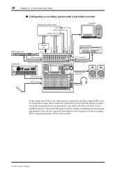
..., track bouncing, and mixdown. You can also control the hard disk recorder's transport section by sending MMC commands from the 01V96 to the 01V96 via the ADAT IN and OUT connectors on the rear panel and via an optional I /O L 16 R IN OUT ... IN OUT IN Computer ADAT IN ADAT OUT WORD CLOCK IN connector MIDI IN MIDI OUT TO HOST USB port MY8-AT etc. Master recorder Effects processor 88 Synthesizer REC SONG SCENE SLOT INPUT connector OMNI OUT connector CH1-4 CH5-8 CH9-12 1 2 3 4 5 6 7 8 9 10 11 12 13 15 PHANTOM +48V A A A A A A A A A A A A 14 B B...
..., track bouncing, and mixdown. You can also control the hard disk recorder's transport section by sending MMC commands from the 01V96 to the 01V96 via the ADAT IN and OUT connectors on the rear panel and via an optional I /O L 16 R IN OUT ... IN OUT IN Computer ADAT IN ADAT OUT WORD CLOCK IN connector MIDI IN MIDI OUT TO HOST USB port MY8-AT etc. Master recorder Effects processor 88 Synthesizer REC SONG SCENE SLOT INPUT connector OMNI OUT connector CH1-4 CH5-8 CH9-12 1 2 3 4 5 6 7 8 9 10 11 12 13 15 PHANTOM +48V A A A A A A A A A A A A 14 B B...
Owner's Manual
Page 39
The 01V96 can provide audio input and output for the DAW. Master recorder Effects processor 88 Synthesizer REC SONG SCENE SLOT INPUT connector OMNI OUT connector CH1-4 CH5-8 CH9-12 1 2 3 4 5 6 7 8 9 10 11 12 13 15 PHANTOM +48V A A A A A A A A A A A A 14 B B ... Sequencer Real-time External Control Surface Modular Synthesis Plug-in System SCENE DIO/SETUP MIDI UTILITY / INSERT/ PAN/ PAIR/ DELAY ROUTING GROUP PATCH DYNAMICS EQ EFFECT FADER MODE VIEW AUX 1 AUX 2 AUX 3 AUX 4 AUX 5 AUX 6 AUX 7 AUX 8 HOME (METER) LAYER 1-16 17-32 MASTER REMOTE ...
The 01V96 can provide audio input and output for the DAW. Master recorder Effects processor 88 Synthesizer REC SONG SCENE SLOT INPUT connector OMNI OUT connector CH1-4 CH5-8 CH9-12 1 2 3 4 5 6 7 8 9 10 11 12 13 15 PHANTOM +48V A A A A A A A A A A A A 14 B B ... Sequencer Real-time External Control Surface Modular Synthesis Plug-in System SCENE DIO/SETUP MIDI UTILITY / INSERT/ PAN/ PAIR/ DELAY ROUTING GROUP PATCH DYNAMICS EQ EFFECT FADER MODE VIEW AUX 1 AUX 2 AUX 3 AUX 4 AUX 5 AUX 6 AUX 7 AUX 8 HOME (METER) LAYER 1-16 17-32 MASTER REMOTE ...
Owner's Manual
Page 41
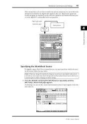
... 14 15 PEAK SIGNAL 16 0 LEVEL10 PHONES DISPLAY ACCESS SCENE MEMORY SCENE DIO/SETUP MIDI UTILITY / INSERT/ PAN/ PAIR/ DELAY ROUTING GROUP PATCH DYNAMICS EQ EFFECT FADER MODE VIEW AUX 1 AUX 2 AUX 3 AUX 4 AUX 5 AUX 6 AUX 7 AUX 8 HOME (METER) LAYER 1-16 17-32 MASTER REMOTE OVER 0 -3 -6 -9 -12 -15 -...28 BUS 4 13 29 BUS 5 14 30 BUS 6 15 31 BUS 7 16 32 BUS 8 STEREO Specifying the Wordclock Source To digitally connect the 01V96 to external devices, you can use the clock information included in the rear panel slot. Note: When you change the wordclock settings on any device...
... 14 15 PEAK SIGNAL 16 0 LEVEL10 PHONES DISPLAY ACCESS SCENE MEMORY SCENE DIO/SETUP MIDI UTILITY / INSERT/ PAN/ PAIR/ DELAY ROUTING GROUP PATCH DYNAMICS EQ EFFECT FADER MODE VIEW AUX 1 AUX 2 AUX 3 AUX 4 AUX 5 AUX 6 AUX 7 AUX 8 HOME (METER) LAYER 1-16 17-32 MASTER REMOTE OVER 0 -3 -6 -9 -12 -15 -...28 BUS 4 13 29 BUS 5 14 30 BUS 6 15 31 BUS 7 16 32 BUS 8 STEREO Specifying the Wordclock Source To digitally connect the 01V96 to external devices, you can use the clock information included in the rear panel slot. Note: When you change the wordclock settings on any device...
Owner's Manual
Page 43
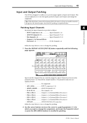
..., and rotate the Parameter wheel or press the [INC]/[DEC] buttons to Input Channels are currently assigned to modify the patching. 01V96-Owner's Manual This section explains how to view the signals patched to Inputs and Outputs. The parameter indicators are explained below No ... Channels 1-16 • ADAT IN channels 1-8 Input Channels 17-24 • Slot channels 1-8 Input Channels 25-32 • Outputs 1-2 of Internal Effects Processor 1-4 ST IN Channels 1-4 Connections and Setup Follow the steps below to view or change the patching. 1 Press the DISPLAY ACCESS [PATCH] button...
..., and rotate the Parameter wheel or press the [INC]/[DEC] buttons to Input Channels are currently assigned to modify the patching. 01V96-Owner's Manual This section explains how to view the signals patched to Inputs and Outputs. The parameter indicators are explained below No ... Channels 1-16 • ADAT IN channels 1-8 Input Channels 17-24 • Slot channels 1-8 Input Channels 25-32 • Outputs 1-2 of Internal Effects Processor 1-4 ST IN Channels 1-4 Connections and Setup Follow the steps below to view or change the patching. 1 Press the DISPLAY ACCESS [PATCH] button...
Owner's Manual
Page 47
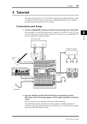
... 14 15 PEAK SIGNAL 16 0 LEVEL10 PHONES DISPLAY ACCESS SCENE MEMORY SCENE DIO/SETUP MIDI UTILITY / INSERT/ PAN/ PAIR/ DELAY ROUTING GROUP PATCH DYNAMICS EQ EFFECT FADER MODE VIEW AUX 1 AUX 2 AUX 3 AUX 4 AUX 5 AUX 6 AUX 7 AUX 8 HOME (METER) LAYER 1-16 17-32 MASTER REMOTE OVER 0 -3 ...16-track hard disk recorder is connected to a digital multitrack recorder. Tutorial 47 5 Tutorial This chapter describes how to use the 01V96 for connection details.) Hard disk recorder Tutorial Track 9-16 OUT IN Track 1-8 OUT IN Headphone amplifier ADAT IN connector ADAT...
... 14 15 PEAK SIGNAL 16 0 LEVEL10 PHONES DISPLAY ACCESS SCENE MEMORY SCENE DIO/SETUP MIDI UTILITY / INSERT/ PAN/ PAIR/ DELAY ROUTING GROUP PATCH DYNAMICS EQ EFFECT FADER MODE VIEW AUX 1 AUX 2 AUX 3 AUX 4 AUX 5 AUX 6 AUX 7 AUX 8 HOME (METER) LAYER 1-16 17-32 MASTER REMOTE OVER 0 -3 ...16-track hard disk recorder is connected to a digital multitrack recorder. Tutorial 47 5 Tutorial This chapter describes how to use the 01V96 for connection details.) Hard disk recorder Tutorial Track 9-16 OUT IN Track 1-8 OUT IN Headphone amplifier ADAT IN connector ADAT...
Owner's Manual
Page 63
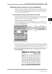
... "Mixdown" is connected to the master recorder's digital output. Change the 01V96's internal patch so that you can also connect the analog output of mixing recorded tracks into a stereo signal, then apply the 01V96's internal effects to the signal, then record it to an external master recorder. In ...the following example, the 01V96 2TR OUT DIGITAL connector is connected to the master recorder's digital input, and the...
... "Mixdown" is connected to the master recorder's digital output. Change the 01V96's internal patch so that you can also connect the analog output of mixing recorded tracks into a stereo signal, then apply the 01V96's internal effects to the signal, then record it to an external master recorder. In ...the following example, the 01V96 2TR OUT DIGITAL connector is connected to the master recorder's digital input, and the...

Owner's Manual
Page 66
... IN section is different from the Effects library, and store the current effects settings of Effects processors 1-4. The Effect | FX1 Lib page enables you to recall effect programs to be used by inserting them into specific channels. 66 Chapter 5-Tutorial Using the Internal Effects The 01V96 features four internal multi-effects processors that you wish to recall...
... IN section is different from the Effects library, and store the current effects settings of Effects processors 1-4. The Effect | FX1 Lib page enables you to recall effect programs to be used by inserting them into specific channels. 66 Chapter 5-Tutorial Using the Internal Effects The 01V96 features four internal multi-effects processors that you wish to recall...

Owner's Manual
Page 67
...the send level of the signals routed from the channel strip section. 7 Press the FADER MODE [AUX1] button. Mixing Recorded Tracks into Effects processor 1. The button indicator lights up. Reverb Room" For purposes of this tutorial, select this example, the faders control the send ...level of the display. 01V96-Owner's Manual Effect program "Reverb Room" is selected for control from Input Channels to Effects processor 1. 9 To adjust the effect return level, use the rotary level control located on the left of the ST...
...the send level of the signals routed from the channel strip section. 7 Press the FADER MODE [AUX1] button. Mixing Recorded Tracks into Effects processor 1. The button indicator lights up. Reverb Room" For purposes of this tutorial, select this example, the faders control the send ...level of the display. 01V96-Owner's Manual Effect program "Reverb Room" is selected for control from Input Channels to Effects processor 1. 9 To adjust the effect return level, use the rotary level control located on the left of the ST...
Owner's Manual
Page 69
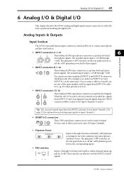
... Analog I/O & Digital I/O 69 6 Analog I/O & Digital I/O This chapter describes the 01V96's analog and digital input/output connectors as well as effects processors, into AD Input Channels. When the AD 15/16 source selector is effective (e.g., B-2 takes priority over A-2). • INPUT connectors 13-16 13 15 14 16... These balanced TRS-type phone connectors accept line-level signals. These switches are effective on (pushed in), signals from the INPUT connectors to any Input Channels. (See page 121 for use INPUT A-2 and INPUT B-2...
... Analog I/O & Digital I/O 69 6 Analog I/O & Digital I/O This chapter describes the 01V96's analog and digital input/output connectors as well as effects processors, into AD Input Channels. When the AD 15/16 source selector is effective (e.g., B-2 takes priority over A-2). • INPUT connectors 13-16 13 15 14 16... These balanced TRS-type phone connectors accept line-level signals. These switches are effective on (pushed in), signals from the INPUT connectors to any Input Channels. (See page 121 for use INPUT A-2 and INPUT B-2...
Owner's Manual
Page 70
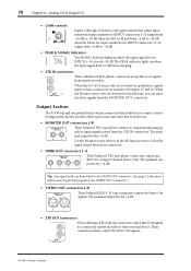
... in ), you to connect a monitoring system, master recorder, effects processors and other external device. Tip: Any signal path can monitor these signals from the MONITOR OUT connectors. R IN OUT 2TR -10dBV (UNBAL) 01V96-Owner's Manual Input sensitivity for INPUT connectors 1-12 ranges from .... • 2TR IN connectors These unbalanced RCA phono connectors accept line-level signals L from master recorders. Output Section The 01V96 top and rear panels feature output connectors that adjust input sensitivity. These connectors always output the Stereo Out signals. Use the ...
... in ), you to connect a monitoring system, master recorder, effects processors and other external device. Tip: Any signal path can monitor these signals from the MONITOR OUT connectors. R IN OUT 2TR -10dBV (UNBAL) 01V96-Owner's Manual Input sensitivity for INPUT connectors 1-12 ranges from .... • 2TR IN connectors These unbalanced RCA phono connectors accept line-level signals L from master recorders. Output Section The 01V96 top and rear panels feature output connectors that adjust input sensitivity. These connectors always output the Stereo Out signals. Use the ...
Owner's Manual
Page 74
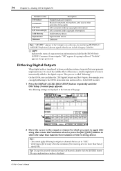
...want to apply dithering, then rotate the Parameter wheel or press the [INC]/[DEC] buttons to "OFF." • Dithering is effective only when the resolution of the 01V96. Tip: To copy the currently-selected setting to a 16-bit DAT recorder. 1 Press the DISPLAY ACCESS [DIO/SETUP] button... repeatedly until the DIO/Setup | Format page appears. On the 01V96, you are displayed at the bottom of the receiving device. "OK" appears if copying is called "dithering." The dithering settings are monitoring IEC958 Part...
...want to apply dithering, then rotate the Parameter wheel or press the [INC]/[DEC] buttons to "OFF." • Dithering is effective only when the resolution of the 01V96. Tip: To copy the currently-selected setting to a 16-bit DAT recorder. 1 Press the DISPLAY ACCESS [DIO/SETUP] button... repeatedly until the DIO/Setup | Format page appears. On the 01V96, you are displayed at the bottom of the receiving device. "OK" appears if copying is called "dithering." The dithering settings are monitoring IEC958 Part...


