
Owner's Manual
Page 2
...-AND-YELLOW : EARTH BLUE : NEUTRAL BROWN : LIVE As the colours of the wires in the mains lead of de volgende Yamaha Service Afdeiing: Yamaha Music Nederland Service Afdeiing Kanaalweg 18-G, 3526 KL UTRECHT Tel. 030-2828425 ● Gooi de batterij niet weg, maar lever hem... product. In the case of other electronic devices. FCC INFORMATION (U.S.A.) 1. The wire which is coloured BLUE must be used according to the instructions found to those products distributed by YAMAHA KEMBLE MUSIC (U.K.) LTD. This equipment generates/uses radio frequencies and, if not installed and...
...-AND-YELLOW : EARTH BLUE : NEUTRAL BROWN : LIVE As the colours of the wires in the mains lead of de volgende Yamaha Service Afdeiing: Yamaha Music Nederland Service Afdeiing Kanaalweg 18-G, 3526 KL UTRECHT Tel. 030-2828425 ● Gooi de batterij niet weg, maar lever hem... product. In the case of other electronic devices. FCC INFORMATION (U.S.A.) 1. The wire which is coloured BLUE must be used according to the instructions found to those products distributed by YAMAHA KEMBLE MUSIC (U.K.) LTD. This equipment generates/uses radio frequencies and, if not installed and...
Owner's Manual
Page 3
... the third prong are provided for your outlet, consult an electrician for long periods of time. 14 Refer all instructions. 5 Do not use this apparatus during lightning storms or when unused for replacement of the obsolete outlet. 10 Protect the power cord from being walked on the...The above warning is located on or pinched particularly at plugs, convenience receptacles, and the point where they exit from the apparatus. 11 Only use caution when moving the cart/ apparatus combination to qualified service personnel. If the provided plug does not fit into the apparatus,...
... the third prong are provided for your outlet, consult an electrician for long periods of time. 14 Refer all instructions. 5 Do not use this apparatus during lightning storms or when unused for replacement of the obsolete outlet. 10 Protect the power cord from being walked on the...The above warning is located on or pinched particularly at plugs, convenience receptacles, and the point where they exit from the apparatus. 11 Only use caution when moving the cart/ apparatus combination to qualified service personnel. If the provided plug does not fit into the apparatus,...
Owner's Manual
Page 4
... a damaged power cord is a fire and electrical shock hazard. • If you notice any cards, check the Yamaha web site to if your card is compatible. Using the unit with liquid or small metal objects on the unit. Consult your dealer. • Do not modify the unit.... shock hazard. • Do not remove the unit's cover. If you think internal inspection, maintenance, or repair is a potential electrical shock hazard. 01V96-Owner's Manual Installing cards that receive direct sunlight. - Locations exposed to oil splashes or steam, such as a wobbly table or slope. - Fire ...
... a damaged power cord is a fire and electrical shock hazard. • If you notice any cards, check the Yamaha web site to if your card is compatible. Using the unit with liquid or small metal objects on the unit. Consult your dealer. • Do not modify the unit.... shock hazard. • Do not remove the unit's cover. If you think internal inspection, maintenance, or repair is a potential electrical shock hazard. 01V96-Owner's Manual Installing cards that receive direct sunlight. - Locations exposed to oil splashes or steam, such as a wobbly table or slope. - Fire ...
Owner's Manual
Page 5
...• This unit has ventilation holes along the top, front, rear, and sides to a memory card, or another unit by improper use or operation of this unit. 01V96-Owner's Manual Do not block them. Leaving it 's covered with a cloth or dust sheet. • This unit is a potential ...fire hazard. ers, and connectors, deteriorates over time. Interference This unit uses high-frequency digital circuits that may cause interference on ...
...• This unit has ventilation holes along the top, front, rear, and sides to a memory card, or another unit by improper use or operation of this unit. 01V96-Owner's Manual Do not block them. Leaving it 's covered with a cloth or dust sheet. • This unit is a potential ...fire hazard. ers, and connectors, deteriorates over time. Interference This unit uses high-frequency digital circuits that may cause interference on ...
Owner's Manual
Page 7
... section or function of signal flow, from those on your personal use . You can help you locate specific information. Installing the 01V96 This unit should be placed on page 27. Conventions Used in square brackets, for your instrument. See "Selecting Display Pages" on ...Aux Outs." References to display page buttons are for example, "move the cursor to operate the 01V96 Digital Mixing Console. The illustrations and LCD screens as shown in use . 01V96-Owner's Manual The Table of the commercially available music sequence data and/or digital audio fi...
... section or function of signal flow, from those on your personal use . You can help you locate specific information. Installing the 01V96 This unit should be placed on page 27. Conventions Used in square brackets, for your instrument. See "Selecting Display Pages" on ...Aux Outs." References to display page buttons are for example, "move the cursor to operate the 01V96 Digital Mixing Console. The illustrations and LCD screens as shown in use . 01V96-Owner's Manual The Table of the commercially available music sequence data and/or digital audio fi...
Owner's Manual
Page 9
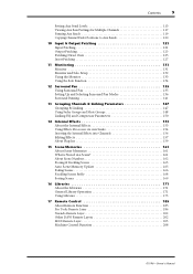
... 131 Monitor and Solo Setup 132 Using the Monitor 133 Using the Solo Function 134 12 Surround Pan 135 Using Surround Pan 135 Setting Up and ...Selecting Surround Pan Modes 136 Surround Panning 141 13 Grouping Channels & Linking Parameters 147 Grouping & Linking 147 Using...14 Internal Effects 153 About the Internal Effects 153 Using Effects Processors via Aux Sends 154 Inserting the Internal ...169 16 Libraries 171 About the Libraries 171 General Library Operation 171 Using Libraries 173 17 Remote Control 185 About Remote Function 185 Pro ...
... 131 Monitor and Solo Setup 132 Using the Monitor 133 Using the Solo Function 134 12 Surround Pan 135 Using Surround Pan 135 Setting Up and ...Selecting Surround Pan Modes 136 Surround Panning 141 13 Grouping Channels & Linking Parameters 147 Grouping & Linking 147 Using...14 Internal Effects 153 About the Internal Effects 153 Using Effects Processors via Aux Sends 154 Inserting the Internal ...169 16 Libraries 171 About the Libraries 171 General Library Operation 171 Using Libraries 173 17 Remote Control 185 About Remote Function 185 Pro ...
Owner's Manual
Page 10
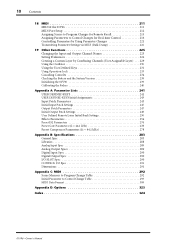
10 Contents 18 MIDI 211 MIDI & the 01V96 211 MIDI Port Setup 212 Assigning Scenes to Program Changes for Remote Recall 215 Assigning Parameters to Control Changes for Real-time Control 216 Controlling Parameters by Using Parameter Changes 221 Transmitting Parameter Settings via MIDI... by Combining Channels (User Assignable Layer) . . . 229 Using the Oscillator 230 Using the User Defined Keys 231 Using Operation Lock 233 Cascading Consoles 234 Checking the Battery and the System Version 238 Initializing the 01V96 239 Calibrating the Faders 240 Appendix A: Parameter Lists 241 USER ...
10 Contents 18 MIDI 211 MIDI & the 01V96 211 MIDI Port Setup 212 Assigning Scenes to Program Changes for Remote Recall 215 Assigning Parameters to Control Changes for Real-time Control 216 Controlling Parameters by Using Parameter Changes 221 Transmitting Parameter Settings via MIDI... by Combining Channels (User Assignable Layer) . . . 229 Using the Oscillator 230 Using the User Defined Keys 231 Using Operation Lock 233 Cascading Consoles 234 Checking the Battery and the System Version 238 Initializing the 01V96 239 Calibrating the Faders 240 Appendix A: Parameter Lists 241 USER ...

Owner's Manual
Page 11
...Output patches enable assignment of channel EQ parameters. • 8 USER-DEFINED KEYS enable you for choosing the Yamaha 01V96 Digital Mixing Console. Welcome 11 1 Welcome 1 Welcome Thank you to assign functions to control 01V96 internal parameters. • ADAT optical connectors • Expansion slot for optional digital I/O, AD, and DA ... to four Omni Outs. • Individual outputs for Stereo Out and Monitor Out • Analog 2TR In and Out for use with switchable +48 V phantom power and 4 line inputs • 12 analog inserts • Any Bus Outs or Channel Inserts can cascade ...
...Output patches enable assignment of channel EQ parameters. • 8 USER-DEFINED KEYS enable you for choosing the Yamaha 01V96 Digital Mixing Console. Welcome 11 1 Welcome 1 Welcome Thank you to assign functions to control 01V96 internal parameters. • ADAT optical connectors • Expansion slot for optional digital I/O, AD, and DA ... to four Omni Outs. • Individual outputs for Stereo Out and Monitor Out • Analog 2TR In and Out for use with switchable +48 V phantom power and 4 line inputs • 12 analog inserts • Any Bus Outs or Channel Inserts can cascade ...
Owner's Manual
Page 12
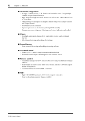
Bus Outs 1-8 can be routed to suit connected devices. ■ Remote Control • Control and manage your 01V96 from your Mac or PC using bundled Studio Manager software. • Remote Layer for remote control of Pro Tools, Nuendo, and other DAWs that support the Pro...time. 12 Chapter 1-Welcome ■ Channel Configuration • 32 Input Channels and four ST IN channels can be assigned to Stereo Buses for use as Scenes ■ Surround Sound • Supports 3-1, 5.1, and 6.1 channel surround sound production • Surround channel outputs can be stored in libraries and...
Bus Outs 1-8 can be routed to suit connected devices. ■ Remote Control • Control and manage your 01V96 from your Mac or PC using bundled Studio Manager software. • Remote Layer for remote control of Pro Tools, Nuendo, and other DAWs that support the Pro...time. 12 Chapter 1-Welcome ■ Channel Configuration • 32 Input Channels and four ST IN channels can be assigned to Stereo Buses for use as Scenes ■ Surround Sound • Supports 3-1, 5.1, and 6.1 channel surround sound production • Surround channel outputs can be stored in libraries and...
Owner's Manual
Page 14
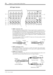
... phone plug Tip (hot) Ring (cold) 2 (hot) Sleeve (ground) B INPUT connectors 13-16 These balanced TRS phone-type connectors accept line-level signals. Use a split cable to insert an external effects processor to AD input channels. 1/4" phone plug Tip (send) Tip (send) Ring (return) 1/4" phone plug Sleeve ...power is not supplied to INSERT jack To processor's input 1/4" phone plug Sleeve (ground) Tip (return) Sleeve (ground) From processor's output 01V96-Owner's Manual INPUT 15 & 16 connectors are available only when the AD 15/16 button is effective. If you connect cables to +4 dB...
... phone plug Tip (hot) Ring (cold) 2 (hot) Sleeve (ground) B INPUT connectors 13-16 These balanced TRS phone-type connectors accept line-level signals. Use a split cable to insert an external effects processor to AD input channels. 1/4" phone plug Tip (send) Tip (send) Ring (return) 1/4" phone plug Sleeve ...power is not supplied to INSERT jack To processor's input 1/4" phone plug Sleeve (ground) Tip (return) Sleeve (ground) From processor's output 01V96-Owner's Manual INPUT 15 & 16 connectors are available only when the AD 15/16 button is effective. If you connect cables to +4 dB...
Owner's Manual
Page 15
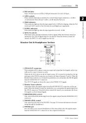
...(pushed in ), the 2TR IN signals (page 24) are selected. B Monitor Source selector This button selects the signals output from this jack. 01V96-Owner's Manual C MONITOR LEVEL control This control adjusts the monitoring level of the PHONES. (See page 131 for each AD Input. The signals output...MONITOR OUT 0 LEVEL10 PHONES 5 4 A 2TR IN/OUT connectors These unbalanced RCA phono connectors input and output line-level signals, and are typically used to AD Input Channels 15 and 16. H AD15/16 selector This button selects AD Input Channel 15 and 16 signals. When the button is ...
...(pushed in ), the 2TR IN signals (page 24) are selected. B Monitor Source selector This button selects the signals output from this jack. 01V96-Owner's Manual C MONITOR LEVEL control This control adjusts the monitoring level of the PHONES. (See page 131 for each AD Input. The signals output...MONITOR OUT 0 LEVEL10 PHONES 5 4 A 2TR IN/OUT connectors These unbalanced RCA phono connectors input and output line-level signals, and are typically used to AD Input Channels 15 and 16. H AD15/16 selector This button selects AD Input Channel 15 and 16 signals. When the button is ...

Owner's Manual
Page 17
..., Aux Out, Stereo Out) levels (see page 33), and displays the corresponding Aux page. (The selected button's indicator lights up.) You can control using the faders. C [SOLO] buttons These buttons solo the selected ST IN channels. B [SEL] buttons These buttons select the ST IN channel you wish.... E Level controls These controls adjust the ST IN channel levels. Pressing one of these buttons switches the Fader mode (see page 34). 01V96-Owner's Manual The indicators to the right of the button indicate the available ST IN channels. Control Surface 17 Control Surface & Rear Panel ...
..., Aux Out, Stereo Out) levels (see page 33), and displays the corresponding Aux page. (The selected button's indicator lights up.) You can control using the faders. C [SOLO] buttons These buttons solo the selected ST IN channels. B [SEL] buttons These buttons select the ST IN channel you wish.... E Level controls These controls adjust the ST IN channel levels. Pressing one of these buttons switches the Fader mode (see page 34). 01V96-Owner's Manual The indicators to the right of the button indicate the available ST IN channels. Control Surface 17 Control Surface & Rear Panel ...
Owner's Manual
Page 18
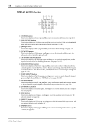
... channel gates and compressors (see page 81). I [DYNAMICS] button This button displays a Dynamics page, enabling you to edit the internal effects processors and use the internal oscillators and view information about installed optional cards. L [VIEW] button This button displays a View page, enabling you to set mix parameters for...'s Manual B [DIO/SETUP] button This button displays a DIO/Setup page, enabling you to view and set up the 01V96, including digital input and output setup and remote control setup (see pgaes 72, 188). F [PAN/ROUTING] button This button displays a Pan/...
... channel gates and compressors (see page 81). I [DYNAMICS] button This button displays a Dynamics page, enabling you to edit the internal effects processors and use the internal oscillators and view information about installed optional cards. L [VIEW] button This button displays a View page, enabling you to set mix parameters for...'s Manual B [DIO/SETUP] button This button displays a DIO/Setup page, enabling you to view and set up the 01V96, including digital input and output setup and remote control setup (see pgaes 72, 188). F [PAN/ROUTING] button This button displays a Pan/...
Owner's Manual
Page 19
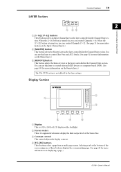
...16. When the [1-16] button is not affected by the layer settings. Selecting a tab at the bottom of the screen using one of the Stereo Bus. C Contrast control This control adjusts the display contrast. Control Surface 19 LAYER Section LAYER 1-16...-32] buttons These buttons select an Input Channel layer as the layer controlled in the Channel Strip section. You can use this layer to control Bus Outs and AUX Sends. (See page 31 for more information on , you can control ...the Remote layer.) Tip: The ST IN section is turned on displaying a page.) 01V96-Owner's Manual
...16. When the [1-16] button is not affected by the layer settings. Selecting a tab at the bottom of the screen using one of the Stereo Bus. C Contrast control This control adjusts the display contrast. Control Surface 19 LAYER Section LAYER 1-16...-32] buttons These buttons select an Input Channel layer as the layer controlled in the Channel Strip section. You can use this layer to control Bus Outs and AUX Sends. (See page 31 for more information on , you can control ...the Remote layer.) Tip: The ST IN section is turned on displaying a page.) 01V96-Owner's Manual
Owner's Manual
Page 20
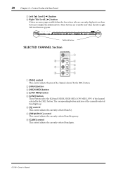
...-MID, LOW-MID, LOW) of the currently-selected band lights up. H [GAIN] control This control adjusts the currently-selected band gain. 01V96-Owner's Manual These buttons are currently displayed, use these buttons to display the additional tabs. Tab Scroll arrow SELECTED CHANNEL Section 6 7 8 SELECTED CHANNEL PAN EQUALIZER Q HIGH HIGH-MID FREQUENCY LOW...
...-MID, LOW-MID, LOW) of the currently-selected band lights up. H [GAIN] control This control adjusts the currently-selected band gain. 01V96-Owner's Manual These buttons are currently displayed, use these buttons to display the additional tabs. Tab Scroll arrow SELECTED CHANNEL Section 6 7 8 SELECTED CHANNEL PAN EQUALIZER Q HIGH HIGH-MID FREQUENCY LOW...
Owner's Manual
Page 23
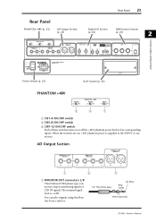
You can select signals using the Monitor Source selector. 1/4" TRS phone plug Tip (hot) Ring (cold) Sleeve (ground) 01V96-Owner's Manual AD Output Section 1 2 3 A MONITOR OUT connectors L/R These balanced TRS phone-type connectors output monitoring signals or 2TR IN signals. When the switches are ...
You can select signals using the Monitor Source selector. 1/4" TRS phone plug Tip (hot) Ring (cold) Sleeve (ground) 01V96-Owner's Manual AD Output Section 1 2 3 A MONITOR OUT connectors L/R These balanced TRS phone-type connectors output monitoring signals or 2TR IN signals. When the switches are ...
Owner's Manual
Page 24
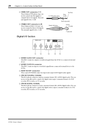
...B WORD CLOCK IN connector This BNC connector inputs a wordclock signal from the 01V96 to the 01V96. C STEREO OUT connectors L/R These balanced XLR-3-32-type connectors output the Stereo Out signals. The connector is typically used to connect the digital stereo input (consumer format) of a DAT recorder,... MD recorder, or CD recorder. 01V96-Owner's Manual C ADAT IN/OUT connectors These optical TOSLINK connectors input and ...
...B WORD CLOCK IN connector This BNC connector inputs a wordclock signal from the 01V96 to the 01V96. C STEREO OUT connectors L/R These balanced XLR-3-32-type connectors output the Stereo Out signals. The connector is typically used to connect the digital stereo input (consumer format) of a DAT recorder,... MD recorder, or CD recorder. 01V96-Owner's Manual C ADAT IN/OUT connectors These optical TOSLINK connectors input and ...
Owner's Manual
Page 26
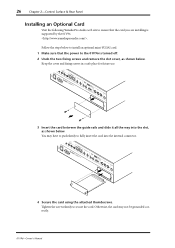
... as shown below . You may not be grounded correctly. 01V96-Owner's Manual 26 Chapter 2-Control Surface & Rear Panel Installing an Optional Card Visit the following Yamaha Pro Audio web site to ensure that the power to the 01V96 is supported by the 01V96. . Keep the cover and fixing screws in ...a safe place for future use. 3 Insert the card between the guide rails and slide it...
... as shown below . You may not be grounded correctly. 01V96-Owner's Manual 26 Chapter 2-Control Surface & Rear Panel Installing an Optional Card Visit the following Yamaha Pro Audio web site to ensure that the power to the 01V96 is supported by the 01V96. . Keep the cover and fixing screws in ...a safe place for future use. 3 Insert the card between the guide rails and slide it...

Owner's Manual
Page 27
... is receiving MIDI data via the MIDI IN port, USB port, or an installed MY8-mLAN card. E MIDI indicator This indicator appears when the 01V96 is write-protected, a padlock icon ( ) appears. B Selected channel This section indicates the Input or Output Channel currently selected by its corresponding [... the currently-selected Scene memory (see page 162). Operating Basics 27 3 Operating Basics This chapter describes basic operations on the 01V96, including how to use the display and operate the controls on the top panel. The second four characters are the Channel ID (e.g., CH1-CH32, BUS1...
... is receiving MIDI data via the MIDI IN port, USB port, or an installed MY8-mLAN card. E MIDI indicator This indicator appears when the 01V96 is write-protected, a padlock icon ( ) appears. B Selected channel This section indicates the Input or Output Channel currently selected by its corresponding [... the currently-selected Scene memory (see page 162). Operating Basics 27 3 Operating Basics This chapter describes basic operations on the 01V96, including how to use the display and operate the controls on the top panel. The second four characters are the Channel ID (e.g., CH1-CH32, BUS1...

Owner's Manual
Page 29
...faders enable you to select one of parameter box, the value flashes. The buttons also enable you to the previous page group, the 01V96 displays the correct page, with the same parameter selected. Move the cursor to the appropriate button, then press the [ENTER] button to turn ... buttons to confirm the change in this type of multiple options. Parameter Boxes The parameter boxes enable you can also select a page by using the controls or buttons on (highlighted) or off (disabled). If you move the cursor to a button, parameter box, rotary control, or fader ...
...faders enable you to select one of parameter box, the value flashes. The buttons also enable you to the previous page group, the 01V96 displays the correct page, with the same parameter selected. Move the cursor to the appropriate button, then press the [ENTER] button to turn ... buttons to confirm the change in this type of multiple options. Parameter Boxes The parameter boxes enable you can also select a page by using the controls or buttons on (highlighted) or off (disabled). If you move the cursor to a button, parameter box, rotary control, or fader ...


