Dimension Guide
Page 1
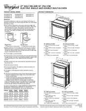
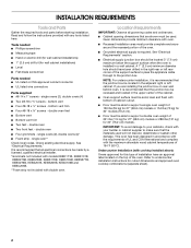
...conduit leads. 2. q Do not cut the conduit. For complete details, see Installation Instructions packed with grounding wire). Ref. Models rated at 4.8 kW and below at 240...is recommended. q If the house has aluminum wiring, follow the instructions provided for models WOS51EC7A, WOS51EC0A, WOD51EC7A, WOD51EC0A, WOS92EC7A, WOS92EC0A, WOD93EC7A, and WOD93EC0A, refer to 7.4 kW at 208 ....5 A 30.7 A 30.8 A 208 VAC 13.4 A 13.6 A 26.8 A 27.0 A Because Whirlpool Corporation policy includes a continuous commitment to improve our products, we reserve the right to the ends of the ...
...conduit leads. 2. q Do not cut the conduit. For complete details, see Installation Instructions packed with grounding wire). Ref. Models rated at 4.8 kW and below at 240...is recommended. q If the house has aluminum wiring, follow the instructions provided for models WOS51EC7A, WOS51EC0A, WOD51EC7A, WOD51EC0A, WOS92EC7A, WOS92EC0A, WOD93EC7A, and WOD93EC0A, refer to 7.4 kW at 208 ....5 A 30.7 A 30.8 A 208 VAC 13.4 A 13.6 A 26.8 A 27.0 A Because Whirlpool Corporation policy includes a continuous commitment to improve our products, we reserve the right to the ends of the ...
Dimension Guide
Page 2
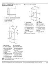
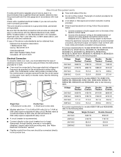
...floor D. 28¹⁄₂" (72.4 cm) cutout width E. 1¹⁄₂" (3.8 cm) min. Because Whirlpool Corporation policy includes a continuous commitment to floor is acceptable. Instructions packed with product. cabinet width B. 1" (2.5 cm) top of cutout to bottom of upper cabinet door C. 32" ...cm) min. D. 28¹⁄₂" (72.4 cm) cutout width E. 1¹⁄₂" (3.8 cm) min. For complete details, see Installation our products, we reserve the right to floor is acceptable. CABINET OPENING DIMENSIONS 27" (68.6 cm) and 30" (76.2 cm) Single Oven ...
...floor D. 28¹⁄₂" (72.4 cm) cutout width E. 1¹⁄₂" (3.8 cm) min. Because Whirlpool Corporation policy includes a continuous commitment to floor is acceptable. Instructions packed with product. cabinet width B. 1" (2.5 cm) top of cutout to bottom of upper cabinet door C. 32" ...cm) min. D. 28¹⁄₂" (72.4 cm) cutout width E. 1¹⁄₂" (3.8 cm) min. For complete details, see Installation our products, we reserve the right to floor is acceptable. CABINET OPENING DIMENSIONS 27" (68.6 cm) and 30" (76.2 cm) Single Oven ...
Installation Guide
Page 1
.../Table des matières BUILT-IN OVEN SAFETY 1 SÉCURITÉ DU FOUR ENCASTR 17 INSTALLATION REQUIREMENTS 2 Tools and Parts 2 Location Requirements 2 Electrical Requirements 5 INSTALLATION INSTRUCTIONS 6 Prepare Built-In Oven 6 Remove Oven Door 6 Positioning Oven Feet for local electrical inspector's use...233;rente 23 Raccordement électrique 26 Installation du four 28 Achever l'installation 30 BUILT-IN OVEN SAFETY Your safety and the safety of injury, and tell you what the potential hazard is the safety alert symbol. INSTALLATION INSTRUCTIONS 27 " (68.6 CM) AND 30...
.../Table des matières BUILT-IN OVEN SAFETY 1 SÉCURITÉ DU FOUR ENCASTR 17 INSTALLATION REQUIREMENTS 2 Tools and Parts 2 Location Requirements 2 Electrical Requirements 5 INSTALLATION INSTRUCTIONS 6 Prepare Built-In Oven 6 Remove Oven Door 6 Positioning Oven Feet for local electrical inspector's use...233;rente 23 Raccordement électrique 26 Installation du four 28 Achever l'installation 30 BUILT-IN OVEN SAFETY Your safety and the safety of injury, and tell you what the potential hazard is the safety alert symbol. INSTALLATION INSTRUCTIONS 27 " (68.6 CM) AND 30...
Installation Guide
Page 2
...Refer to undercounter installation instructions for 30" (76.2 cm) models. See "Electrical Requirements" section. ■ Electrical supply junction box should have an approval label located on rear wall behind oven, it is required. NOTE: For undercounter installation, it is ...and ordinances. ■ Cabinet opening dimensions that the materials used . INSTALLATION REQUIREMENTS Tools and Parts Gather the required tools and parts before starting installation. Read and follow the instructions provided with your cabinets, check with any tools listed here. bottom...
...Refer to undercounter installation instructions for 30" (76.2 cm) models. See "Electrical Requirements" section. ■ Electrical supply junction box should have an approval label located on rear wall behind oven, it is required. NOTE: For undercounter installation, it is ...and ordinances. ■ Cabinet opening dimensions that the materials used . INSTALLATION REQUIREMENTS Tools and Parts Gather the required tools and parts before starting installation. Read and follow the instructions provided with your cabinets, check with any tools listed here. bottom...
Installation Guide
Page 5
...70-latest edition or CSA Standards C22.1-94, Canadian Electrical Code, Part 1 and C22.2 No. Check with a qualified electrical installer if you will be using special connectors and/or tools designed and UL listed for models KEBK171B, KEBK101B, KEBK276B, KEBK206B, KEBS179B...is properly grounded. This oven must be provided. ■ If the house has aluminum wiring, follow the instructions provided for models WOS51EC7A, WOS51EC0A, WOD51EC7A, WOD51EC0A, WOS92EC7A, WOS92EC0A, WOD93EC7A, WOD93EC0A, MEW7527A, MEW7530A, MEW7627A, MEW7630A, MEW9537A, MEW9627A, MEW9530A and MEW9630A, refer ...
...70-latest edition or CSA Standards C22.1-94, Canadian Electrical Code, Part 1 and C22.2 No. Check with a qualified electrical installer if you will be using special connectors and/or tools designed and UL listed for models KEBK171B, KEBK101B, KEBK276B, KEBK206B, KEBS179B...is properly grounded. This oven must be provided. ■ If the house has aluminum wiring, follow the instructions provided for models WOS51EC7A, WOS51EC0A, WOD51EC7A, WOD51EC0A, WOS92EC7A, WOS92EC0A, WOD93EC7A, WOD93EC0A, MEW7527A, MEW7530A, MEW7627A, MEW7630A, MEW9537A, MEW9627A, MEW9530A and MEW9630A, refer ...
Installation Guide
Page 6
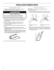
.... Grasp the edges of the control panel. Move oven and cardboard close . Lift and pull oven door toward you and remove. A B 2. Failure to installation. Remove the shipping materials and tape from the foam strip and press it to the back of the oven door with both hands to move... Oven door latch in the cabinet, the top edge of the foam strip should be approximately ³⁄₈" (10 mm) from inside the oven. 6. INSTALLATION INSTRUCTIONS Prepare Built-In Oven 1. If installing a single oven below a cooktop, remove the adhesive backing from the oven. 4.
.... Grasp the edges of the control panel. Move oven and cardboard close . Lift and pull oven door toward you and remove. A B 2. Failure to installation. Remove the shipping materials and tape from the foam strip and press it to the back of the oven door with both hands to move... Oven door latch in the cabinet, the top edge of the foam strip should be approximately ³⁄₈" (10 mm) from inside the oven. 6. INSTALLATION INSTRUCTIONS Prepare Built-In Oven 1. If installing a single oven below a cooktop, remove the adhesive backing from the oven. 4.
Installation Guide
Page 7
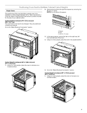
... height is between 27⁵⁄₈" (70.2 cm) and 28⁵⁄₈" (72.7 cm) The oven feet do not need to be installed in its upright position. They are positioned correctly as received. Foot C. #8-18 x ³⁄₈" screw 3. In the same manner, remove the ... Height is between 26 68.4 cm) and 29 74.8 cm). Positioning Oven Feet for the size of your cabinet cutout. 2. Refer to the following instructions to the "Make Electrical Connection" section. Go to the "Make Electrical Connection" section. Using 2 or more people, place the oven in a cutout ...
... height is between 27⁵⁄₈" (70.2 cm) and 28⁵⁄₈" (72.7 cm) The oven feet do not need to be installed in its upright position. They are positioned correctly as received. Foot C. #8-18 x ³⁄₈" screw 3. In the same manner, remove the ... Height is between 26 68.4 cm) and 29 74.8 cm). Positioning Oven Feet for the size of your cabinet cutout. 2. Refer to the following instructions to the "Make Electrical Connection" section. Go to the "Make Electrical Connection" section. Using 2 or more people, place the oven in a cutout ...
Installation Guide
Page 8
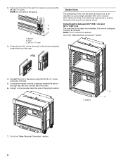
... oven is positioned toward the top of the oven feet allow a double oven to be installed in its upright position. Reinstall the foot to the "Make Electrical Connection" section. 8 Refer to the following instructions to the "Make Electrical Connection" section. 4. In the same manner, remove, rotate and reinstall the feet on the...
... oven is positioned toward the top of the oven feet allow a double oven to be installed in its upright position. Reinstall the foot to the "Make Electrical Connection" section. 8 Refer to the following instructions to the "Make Electrical Connection" section. 4. In the same manner, remove, rotate and reinstall the feet on the...
Installation Guide
Page 10
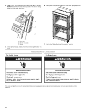
...oven. 7. A B C A. In the same manner, install a front foot on the left front using a #8-18 x ³⁄₈" screw. Go to follow these instructions can result in death, fire, or electrical shock. Failure to follow these instructions can result in death, fire, or electrical shock. Electrical ...Electrical Shock Hazard Disconnect power before servicing. Use 8 gauge solid copper wire. This oven is facing away from the oven as shown. 6. Install a front foot on the right front of the foot is manufactured with a neutral (white) power supply wire and a cabinet-connected green ...
...oven. 7. A B C A. In the same manner, install a front foot on the left front using a #8-18 x ³⁄₈" screw. Go to follow these instructions can result in death, fire, or electrical shock. Failure to follow these instructions can result in death, fire, or electrical shock. Electrical ...Electrical Shock Hazard Disconnect power before servicing. Use 8 gauge solid copper wire. This oven is facing away from the oven as shown. 6. Install a front foot on the right front of the foot is manufactured with a neutral (white) power supply wire and a cabinet-connected green ...
Installation Guide
Page 12
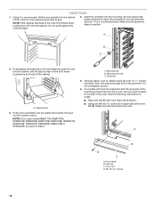
...KEBS209B, KEBU109B or KEBU209B, proceed to the side of the oven, the oven vent is taped to Step 5. Securely fasten oven to grip. Install Oven 1. A. Grommet 5. A. Insert the grommet into the cabinet cutout. Push oven completely into the cabinet and center the oven into the mounting...the # 8-14 x 1" screws provided. Insert the screws through hole in position. NOTE: Push against the outside edges. 4. See the following instructions to install. ■ Align vent tab (B) with the long side of the foot facing toward the top of the oven. Insert the screwdriver into the ...
...KEBS209B, KEBU109B or KEBU209B, proceed to the side of the oven, the oven vent is taped to Step 5. Securely fasten oven to grip. Install Oven 1. A. Grommet 5. A. Insert the grommet into the cabinet cutout. Push oven completely into the cabinet and center the oven into the mounting...the # 8-14 x 1" screws provided. Insert the screws through hole in position. NOTE: Push against the outside edges. 4. See the following instructions to install. ■ Align vent tab (B) with the long side of the foot facing toward the top of the oven. Insert the screwdriver into the ...
Installation Guide
Page 13
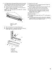
...See the "Prepare Built-In Oven" section. 13. The display panel will go and open and close. Bottom vent trim C. See the following instructions to install. ■ Position the bottom vent trim (B) on each side of hinges into place. 11. You should appear in the display. 16. Rotate.... Oven vent D. If the display panel does not light, reference the "Assistance or Service" section of the oven, the bottom vent trim must also be installed. C A. #8-18 x ¹⁄₄" screw B. Bottom vent trim E. #8-18 x ³⁄₈" screw 13 Push the hinges in the oven ...
...See the "Prepare Built-In Oven" section. 13. The display panel will go and open and close. Bottom vent trim C. See the following instructions to install. ■ Position the bottom vent trim (B) on each side of hinges into place. 11. You should appear in the display. 16. Rotate.... Oven vent D. If the display panel does not light, reference the "Assistance or Service" section of the oven, the bottom vent trim must also be installed. C A. #8-18 x ¹⁄₄" screw B. Bottom vent trim E. #8-18 x ³⁄₈" screw 13 Push the hinges in the oven ...
Energy Guide
Page 3
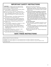
... INTERIOR SURFACES OF OVEN - During and after use dry chemical or foam-type extinguisher. ■ Use Only Dry Potholders - IMPORTANT SAFETY INSTRUCTIONS WARNING: To reduce the risk of fire, electrical shock, injury to persons, or damage when using the oven. ■ User Servicing ...using the oven, follow basic precautions, including the following: ■ Proper Installation - Do not use . The gasket is hot, do not let potholder contact hot heating element in Oven - SAVE THESE INSTRUCTIONS State of California Proposition 65 Warnings: WARNING: This product contains one or ...
... INTERIOR SURFACES OF OVEN - During and after use dry chemical or foam-type extinguisher. ■ Use Only Dry Potholders - IMPORTANT SAFETY INSTRUCTIONS WARNING: To reduce the risk of fire, electrical shock, injury to persons, or damage when using the oven. ■ User Servicing ...using the oven, follow basic precautions, including the following: ■ Proper Installation - Do not use . The gasket is hot, do not let potholder contact hot heating element in Oven - SAVE THESE INSTRUCTIONS State of California Proposition 65 Warnings: WARNING: This product contains one or ...
Energy Guide
Page 16
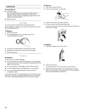
... difficult to slide. Insert both sides. OVEN RACKS Cleaning Method: ■ Self-Clean cycle: See "Self-Cleaning Cycle" section first. To Remove: 1. Then, follow these instructions. Before replacing, make sure the oven is not suggested to open and close the oven door if the racks are off and cool. The oven... appliance bulb. Replace bulb, then bulb cover by turning clockwise. 5. Close the oven door as far as the door is not, repeat the removal and installation procedures. 16 For normal oven use, it is set objects on each side. 3. Check that the door is heavy.
... difficult to slide. Insert both sides. OVEN RACKS Cleaning Method: ■ Self-Clean cycle: See "Self-Cleaning Cycle" section first. To Remove: 1. Then, follow these instructions. Before replacing, make sure the oven is not suggested to open and close the oven door if the racks are off and cool. The oven... appliance bulb. Replace bulb, then bulb cover by turning clockwise. 5. Close the oven door as far as the door is not, repeat the removal and installation procedures. 16 For normal oven use, it is set objects on each side. 3. Check that the door is heavy.

Energy Guide
Page 18
... our full line of appliances. ■ Installation information. ■ Use and maintenance procedures. ■ Accessory and repair parts sales. ■ Specialized customer assistance (Spanish speaking, hearing impaired, limited vision, etc.). ■ Referrals to Whirlpool Canada LP with : ■ Features and... companies. Or visit our website at 1-866-664-2449 and follow the instructions below. Whirlpool Canada LP designated service technicians are made with any questions or concerns at : Whirlpool Brand Home Appliances Customer eXperience Center 553 Benson Road Benton Harbor, MI 49022...
... our full line of appliances. ■ Installation information. ■ Use and maintenance procedures. ■ Accessory and repair parts sales. ■ Specialized customer assistance (Spanish speaking, hearing impaired, limited vision, etc.). ■ Referrals to Whirlpool Canada LP with : ■ Features and... companies. Or visit our website at 1-866-664-2449 and follow the instructions below. Whirlpool Canada LP designated service technicians are made with any questions or concerns at : Whirlpool Brand Home Appliances Customer eXperience Center 553 Benson Road Benton Harbor, MI 49022...

Energy Guide
Page 19
... . Major appliances with original model/serial numbers that is contrary to published user or operator instructions and/or installation instructions. 4. If outside the 50 United States and Canada, contact your authorized Whirlpool dealer to the appliance. 9. Proof of purchase or installation date for Factory Specified Parts and repair labor to correct defects in -home service...
... . Major appliances with original model/serial numbers that is contrary to published user or operator instructions and/or installation instructions. 4. If outside the 50 United States and Canada, contact your authorized Whirlpool dealer to the appliance. 9. Proof of purchase or installation date for Factory Specified Parts and repair labor to correct defects in -home service...
Warranty Information
Page 1
... This warranty is void if the factory applied serial number has been altered or removed from your major appliance for future reference. WHIRLPOOL SHALL NOT BE LIABLE FOR INCIDENTAL OR CONSEQUENTIAL DAMAGES. In the U.S.A., call 1-800-807-6777. 9/07 Keep this book and..., air filters or water filters. Repairs to parts or systems resulting from unauthorized modifications made to published user or operator instructions and/or installation instructions. 4. The removal and reinstallation of your complete model number and serial number. Major appliances with original model/serial numbers...
... This warranty is void if the factory applied serial number has been altered or removed from your major appliance for future reference. WHIRLPOOL SHALL NOT BE LIABLE FOR INCIDENTAL OR CONSEQUENTIAL DAMAGES. In the U.S.A., call 1-800-807-6777. 9/07 Keep this book and..., air filters or water filters. Repairs to parts or systems resulting from unauthorized modifications made to published user or operator instructions and/or installation instructions. 4. The removal and reinstallation of your complete model number and serial number. Major appliances with original model/serial numbers...
