
Owners Manual
Page 3
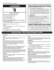
... an adapter. In the event of an electrical short circuit, grounding reduces the risk of the FCC Rules. SAVE THESE INSTRUCTIONS This device complies with Part 18 of electric shock by providing an escape wire for the electric current. OPERATING YOUR MICROWAVE OVEN Settings Clock The clock is counting down. Choose...
... an adapter. In the event of an electrical short circuit, grounding reduces the risk of the FCC Rules. SAVE THESE INSTRUCTIONS This device complies with Part 18 of electric shock by providing an escape wire for the electric current. OPERATING YOUR MICROWAVE OVEN Settings Clock The clock is counting down. Choose...
Owners Manual
Page 6
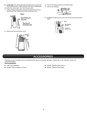
...; Cavity light: The cavity light bulb is located at the top front of the microwave oven, under the bulb cover, and is a list of available parts and supplies which may be purchased separately.
...; Cavity light: The cavity light bulb is located at the top front of the microwave oven, under the bulb cover, and is a list of available parts and supplies which may be purchased separately.
Owners Manual
Page 8
...the customer. In-home instruction on the duration of implied warranties of the appliance. The cost of non-genuine Whirlpool parts or accessories. This warranty gives you specific legal rights, and you . Please take a few minutes to correct product damage or... defects caused by a Whirlpool designated service company. 11. In the U.S. specified replacement parts and repair 4. Pickup or delivery. WHIRLPOOL® MAJOR APPLIANCE LIMITED WARRANTY ATTACH YOUR RECEIPT HERE. Proof of the Use and Care ...
...the customer. In-home instruction on the duration of implied warranties of the appliance. The cost of non-genuine Whirlpool parts or accessories. This warranty gives you specific legal rights, and you . Please take a few minutes to correct product damage or... defects caused by a Whirlpool designated service company. 11. In the U.S. specified replacement parts and repair 4. Pickup or delivery. WHIRLPOOL® MAJOR APPLIANCE LIMITED WARRANTY ATTACH YOUR RECEIPT HERE. Proof of the Use and Care ...
Installation Instructions
Page 1
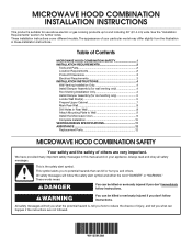
... up to Wall 9 Install the Microwave Oven 9 Complete Installation 10 VENTING DESIGN SPECIFICATIONS 11 ASSISTANCE 12 Replacement Parts 12 MICROWAVE HOOD COMBINATION SAFETY Your safety and the safety of your particular model may differ slightly from the ...illustration in this manual and on your appliance. Table of Contents MICROWAVE HOOD COMBINATION SAFETY 1 INSTALLATION REQUIREMENTS 2 Tools and Parts 2 Location Requirements 2 Product Dimensions 3 Electrical Requirements 3 INSTALLATION INSTRUCTIONS 4 Wall Venting Installation Only 4 Install Damper Assembly (for wall ...
... up to Wall 9 Install the Microwave Oven 9 Complete Installation 10 VENTING DESIGN SPECIFICATIONS 11 ASSISTANCE 12 Replacement Parts 12 MICROWAVE HOOD COMBINATION SAFETY Your safety and the safety of your particular model may differ slightly from the ...illustration in this manual and on your appliance. Table of Contents MICROWAVE HOOD COMBINATION SAFETY 1 INSTALLATION REQUIREMENTS 2 Tools and Parts 2 Location Requirements 2 Product Dimensions 3 Electrical Requirements 3 INSTALLATION INSTRUCTIONS 4 Wall Venting Installation Only 4 Install Damper Assembly (for wall ...
Installation Instructions
Page 2
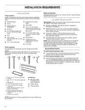
... drill bits ■■ Caulking gun and weatherproof caulking ■■ 3/4" (1.9 cm) hole saw compound ■■ Duct tape Parts supplied For information on model, grease filter and charcoal filter may be free of any tools listed here. ■■ Measuring tape &#... plate (Located on the upper polyfoam) ■■ Grease filters ■■ Charcoal filters NOTE: Depending on reordering, see the "Replacement Parts" section. For other damages. The location must be combined. 2 See the "Installation Dimensions" illustration. ■■ Minimum one 2" x ...
... drill bits ■■ Caulking gun and weatherproof caulking ■■ 3/4" (1.9 cm) hole saw compound ■■ Duct tape Parts supplied For information on model, grease filter and charcoal filter may be free of any tools listed here. ■■ Measuring tape &#... plate (Located on the upper polyfoam) ■■ Grease filters ■■ Charcoal filters NOTE: Depending on reordering, see the "Replacement Parts" section. For other damages. The location must be combined. 2 See the "Installation Dimensions" illustration. ■■ Minimum one 2" x ...
Installation Instructions
Page 3
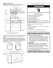
...electrician or serviceman if the grounding instructions are deeper than 15" (38.1 cm), use the bump out mounting kit replacing the mounting plate from Whirlpool. 12" DEEPER 14" 14" DEEPER 15" mounting plate Bump out mounting bracket Product Dimensions *Overall depth of product will vary slightly depending ...the microwave oven is not provided but no more than 14" (35.6 cm) but can be inside the upper cabinet. The bump out mounting kit (part # W11185746) is properly grounded. The plug must be plugged into a grounded 3 prong outlet. Grounded 3 prong outlet *24" (61 cm) is ...
...electrician or serviceman if the grounding instructions are deeper than 15" (38.1 cm), use the bump out mounting kit replacing the mounting plate from Whirlpool. 12" DEEPER 14" 14" DEEPER 15" mounting plate Bump out mounting bracket Product Dimensions *Overall depth of product will vary slightly depending ...the microwave oven is not provided but no more than 14" (35.6 cm) but can be inside the upper cabinet. The bump out mounting kit (part # W11185746) is properly grounded. The plug must be plugged into a grounded 3 prong outlet. Grounded 3 prong outlet *24" (61 cm) is ...
Installation Instructions
Page 5
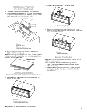
... installation. 5 Screws J. Check that the damper blade hinge is at the top, and the damper blade opens away from packaging upper foam (see item J in "Parts Supplied" section), attach both wall and upper vent installation) 1. See illustrations in "Possible Wall Stud Configurations." B C B A. Secure damper assembly with screw removed from the bottom...
... installation. 5 Screws J. Check that the damper blade hinge is at the top, and the damper blade opens away from packaging upper foam (see item J in "Parts Supplied" section), attach both wall and upper vent installation) 1. See illustrations in "Possible Wall Stud Configurations." B C B A. Secure damper assembly with screw removed from the bottom...
Installation Instructions
Page 7
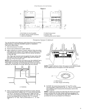
... in the top of the upper cabinet. The "Rear wall" arrows must be sure the "Rear Wall" arrows align to the thickest part of the rear wall (for example, the thickness of upper cabinet. Centerline 4. A. Wall stud centerlines D. Place mounting plate against the ... REAR WALL A,D C E F A. These are for lag screws E. And 11⁄2" (3.8 cm) diameter for installation. The Outlet Box Kit (part #W11082816) is maintained. See below install steps: 1. Power supply cord bushing 5. Cabinet opening vertical centerline C. Mounting plate center markers Prepare Upper Cabinet You...
... in the top of the upper cabinet. The "Rear wall" arrows must be sure the "Rear Wall" arrows align to the thickest part of the rear wall (for example, the thickness of upper cabinet. Centerline 4. A. Wall stud centerlines D. Place mounting plate against the ... REAR WALL A,D C E F A. These are for lag screws E. And 11⁄2" (3.8 cm) diameter for installation. The Outlet Box Kit (part #W11082816) is maintained. See below install steps: 1. Power supply cord bushing 5. Cabinet opening vertical centerline C. Mounting plate center markers Prepare Upper Cabinet You...
Installation Instructions
Page 12
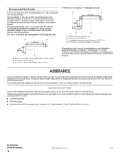
... the door. ■■ Damper assembly ■■ Mounting plate ■■ Mounting Screw Kit (includes parts A through G in "Parts Supplied" in the system. When you call, you will need additional assistance, call us at our toll-free ... must be installed to -round transition piece must not exceed the equivalent of 140 ft (42.7 m) for equivalent lengths. A B 6 ft (1.8 m) 2 ft (0.6 m) C D A. Replacement Parts If any of the installation hardware needs to -round transition piece = 5 ft (1.5 m) D. 2 ft (0.6 m) + 6 ft (1.8 m) straight = 8 ft (2.4 m) 2 ft (0.6 ...
... the door. ■■ Damper assembly ■■ Mounting plate ■■ Mounting Screw Kit (includes parts A through G in "Parts Supplied" in the system. When you call, you will need additional assistance, call us at our toll-free ... must be installed to -round transition piece must not exceed the equivalent of 140 ft (42.7 m) for equivalent lengths. A B 6 ft (1.8 m) 2 ft (0.6 m) C D A. Replacement Parts If any of the installation hardware needs to -round transition piece = 5 ft (1.5 m) D. 2 ft (0.6 m) + 6 ft (1.8 m) straight = 8 ft (2.4 m) 2 ft (0.6 ...


