
Owners Manual
Page 1
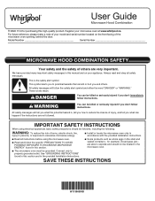
... to reduce the chance of your microwave oven at www.whirlpool.ca. All safety messages will tell you and others are very important. All safety messages will follow instructions. Model Number Serial Number MICROWAVE HOOD COMBINATION SAFETY Your safety and the safety of burns, electric shock, fire, injury to persons, or exposure to excessive microwave energy: I The microwave oven must be followed, including the following...
... to reduce the chance of your microwave oven at www.whirlpool.ca. All safety messages will tell you and others are very important. All safety messages will follow instructions. Model Number Serial Number MICROWAVE HOOD COMBINATION SAFETY Your safety and the safety of burns, electric shock, fire, injury to persons, or exposure to excessive microwave energy: I The microwave oven must be followed, including the following...
Owners Manual
Page 2
... locations. I To reduce the risk of table or counter. Remove wire twist-ties from paper or plastic bags before placing bags in the oven cavity: - Corrosive cleaning agents, such as water, coffee, or tea are placed inside the oven ignite, keep oven door closed, turn the fan on hood or filter. SAVE THESE INSTRUCTIONS PRECAUTIONS TO AVOID POSSIBLE EXPOSURE TO EXCESSIVE MICROWAVE ENERGY (a) Do not attempt to operate...
... locations. I To reduce the risk of table or counter. Remove wire twist-ties from paper or plastic bags before placing bags in the oven cavity: - Corrosive cleaning agents, such as water, coffee, or tea are placed inside the oven ignite, keep oven door closed, turn the fan on hood or filter. SAVE THESE INSTRUCTIONS PRECAUTIONS TO AVOID POSSIBLE EXPOSURE TO EXCESSIVE MICROWAVE ENERGY (a) Do not attempt to operate...
Owners Manual
Page 3
... use an extension cord. Repeat to disable button tones. End of the FCC Rules. If the power supply cord is a 12 hour (12:00-11:59) clock. Touch CLOCK, enter time, then touch CLOCK or the Start control. Timer With the microwave oven in the display. To keep the microwave oven from overheating, the auto hood fan will not work. Tones Open door, press and hold number keypad "4" for the hood control buttons and Cancel) will automatically turn on . Standby Power Mode...
... use an extension cord. Repeat to disable button tones. End of the FCC Rules. If the power supply cord is a 12 hour (12:00-11:59) clock. Touch CLOCK, enter time, then touch CLOCK or the Start control. Timer With the microwave oven in the display. To keep the microwave oven from overheating, the auto hood fan will not work. Tones Open door, press and hold number keypad "4" for the hood control buttons and Cancel) will automatically turn on . Standby Power Mode...
Owners Manual
Page 4
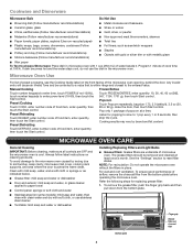
..., touch POWER (if not 100%), touch number keypads to reset filter status. MICROWAVE OVEN CARE General Cleaning IMPORTANT: Before cleaning, make sure all controls are underside of airflow, remove the charcoal filter from the bottom plate. Preset Cooking Touch COOK, enter number code of food item, enter quantity, then touch the Start control. Listen for replacing grease filter: 1. Microwave Oven Use For list of water beside it. Preset Reheating Touch REHEAT, enter number code of food item, enter quantity, then touch the Start control. Touch DEFROST, enter number code of cook...
..., touch POWER (if not 100%), touch number keypads to reset filter status. MICROWAVE OVEN CARE General Cleaning IMPORTANT: Before cleaning, make sure all controls are underside of airflow, remove the charcoal filter from the bottom plate. Preset Cooking Touch COOK, enter number code of food item, enter quantity, then touch the Start control. Listen for replacing grease filter: 1. Microwave Oven Use For list of water beside it. Preset Reheating Touch REHEAT, enter number code of food item, enter quantity, then touch the Start control. Touch DEFROST, enter number code of cook...
Owners Manual
Page 5
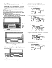
For wall and roof ventilation: To ensure good performance of airflow, remove the charcoal filter from the "T" shaped bottom lighting cover. 2. Using a Phillips screwdriver, remove the 4 screws from the bottom plate before operating the microwave oven. Terminal 4. Using a Phillips screwdriver, reattach the 4 screws back to reset filter status. Hook Finger grip Grease filter and charcoal filter Bottom plate 2. Terminal Charcoal filter 3. See the "Settings" section to "T" shape bottom lighting cover. To remove the grease filter first, push finger grip back and...
For wall and roof ventilation: To ensure good performance of airflow, remove the charcoal filter from the "T" shaped bottom lighting cover. 2. Using a Phillips screwdriver, remove the 4 screws from the bottom plate before operating the microwave oven. Terminal 4. Using a Phillips screwdriver, reattach the 4 screws back to reset filter status. Hook Finger grip Grease filter and charcoal filter Bottom plate 2. Terminal Charcoal filter 3. See the "Settings" section to "T" shape bottom lighting cover. To remove the grease filter first, push finger grip back and...
Owners Manual
Page 6
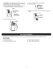
... light: The cavity light bulb is located at the top front of the microwave oven, under the bulb cover, and is a list of available parts and supplies which may be purchased separately. Screw Second left top cover. 3. Reattach the second top vent cover with the screw removed in step1. Cleaning Supplies ■■ Heavy-duty degreaser ■■ Affresh® Stainless Steel Cleaner ■■ Affresh® Kitchen...
... light: The cavity light bulb is located at the top front of the microwave oven, under the bulb cover, and is a list of available parts and supplies which may be purchased separately. Screw Second left top cover. 3. Reattach the second top vent cover with the screw removed in step1. Cleaning Supplies ■■ Heavy-duty degreaser ■■ Affresh® Stainless Steel Cleaner ■■ Affresh® Kitchen...
Owners Manual
Page 7
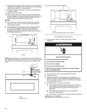
... operate, call , refer to cool the microwave oven. Mississauga Ontario L5N 0B7 Please include a daytime phone number in the "Microwave Oven Care" section. Open and close the door, then start the cycle. ■■ Control: Make sure control is OFF. Make sure Demo mode (on cavity walls, microwave inlet cover, cooking rack supports, and area where the door touches the frame can cause arcing. If a message about the door appears in the display, the door...
... operate, call , refer to cool the microwave oven. Mississauga Ontario L5N 0B7 Please include a daytime phone number in the "Microwave Oven Care" section. Open and close the door, then start the cycle. ■■ Control: Make sure control is OFF. Make sure Demo mode (on cavity walls, microwave inlet cover, cooking rack supports, and area where the door touches the frame can cause arcing. If a message about the door appears in the display, the door...
Owners Manual
Page 8
... in materials or 5. This limited warranty is installed, or installation instructions. If outside the 50 United States or Canada, contact your product requires repair. specified replacement parts and repair 4. Consumable parts (e.g., light bulbs, batteries, air or water filters, preservation solutions). In the event of the Use and Care Guide or visit producthelp.whirlpool.com. 2. warranty period. 9. Service must be borne by our authorized Whirlpool Service Providers. Food or medicine loss due to...
... in materials or 5. This limited warranty is installed, or installation instructions. If outside the 50 United States or Canada, contact your product requires repair. specified replacement parts and repair 4. Consumable parts (e.g., light bulbs, batteries, air or water filters, preservation solutions). In the event of the Use and Care Guide or visit producthelp.whirlpool.com. 2. warranty period. 9. Service must be borne by our authorized Whirlpool Service Providers. Food or medicine loss due to...
Specification Sheet
Page 1
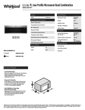
... on 24" minimum install for planning purposes only. ft. General Features & Properties Tap-To-Open Door Concealed Touch Controls 90º Hinge Door Popcorn Preset 1,000-Watt Cooking Power Turntable On/Off Option Dishwasher-Safe Turntable Plate Microwave Presets Add 30 Seconds Option Electrical Details Amps 15 Volts 120 Technical Details Microwave Type CFMs Lighting Type Number of Speeds Venting Type Dimensions Product Dimensions (H x W x D) Depth with Door Open 90° Cutout Dimensions (W x D) Reference Material Install Guide Use & Care Guide Warranty Over-theRange 400...
... on 24" minimum install for planning purposes only. ft. General Features & Properties Tap-To-Open Door Concealed Touch Controls 90º Hinge Door Popcorn Preset 1,000-Watt Cooking Power Turntable On/Off Option Dishwasher-Safe Turntable Plate Microwave Presets Add 30 Seconds Option Electrical Details Amps 15 Volts 120 Technical Details Microwave Type CFMs Lighting Type Number of Speeds Venting Type Dimensions Product Dimensions (H x W x D) Depth with Door Open 90° Cutout Dimensions (W x D) Reference Material Install Guide Use & Care Guide Warranty Over-theRange 400...
Installation Instructions
Page 1
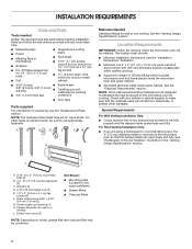
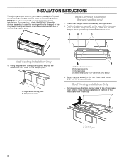
...and Parts 2 Location Requirements 2 Product Dimensions 3 Electrical Requirements 3 INSTALLATION INSTRUCTIONS 4 Wall Venting Installation Only 4 Install Damper Assembly (for wall venting only 4 Roof Venting Installation Only 4 Install Damper Assembly (for roof venting only 5 Locate Wall Stud(s 5 Prepare Upper Cabinet 7 Mark Rear Wall 8 Drill Holes in these installation instructions. WARNING You can happen if the instructions are very important. This is , tell you how to Wall 9 Install the Microwave Oven 9 Complete Installation 10 VENTING DESIGN SPECIFICATIONS...
...and Parts 2 Location Requirements 2 Product Dimensions 3 Electrical Requirements 3 INSTALLATION INSTRUCTIONS 4 Wall Venting Installation Only 4 Install Damper Assembly (for wall venting only 4 Roof Venting Installation Only 4 Install Damper Assembly (for roof venting only 5 Locate Wall Stud(s 5 Prepare Upper Cabinet 7 Mark Rear Wall 8 Drill Holes in these installation instructions. WARNING You can happen if the instructions are very important. This is , tell you how to Wall 9 Install the Microwave Oven 9 Complete Installation 10 VENTING DESIGN SPECIFICATIONS...
Installation Instructions
Page 2
...;at-head bolts (2) C. Power supply cord bushing (1) H. Washers (2) D. 3/16" (4.8 mm) toggle nuts (2) E. 1/4" x 2" (0.6 cm x 5.1 cm) lag screws (2) F. Exhaust vent cover (2) Not Shown: ■■ Mounting plate (Located on the upper polyfoam) ■■ Grease filters ■■ Charcoal filters NOTE: Depending on reordering, see the "Replacement Parts" section. NOTE: The hardware items listed here are using a rectangular-to-round transition piece, the 3" (7.6 cm) clearance needs to make sure that...
...;at-head bolts (2) C. Power supply cord bushing (1) H. Washers (2) D. 3/16" (4.8 mm) toggle nuts (2) E. 1/4" x 2" (0.6 cm x 5.1 cm) lag screws (2) F. Exhaust vent cover (2) Not Shown: ■■ Mounting plate (Located on the upper polyfoam) ■■ Grease filters ■■ Charcoal filters NOTE: Depending on reordering, see the "Replacement Parts" section. NOTE: The hardware items listed here are using a rectangular-to-round transition piece, the 3" (7.6 cm) clearance needs to make sure that...
Installation Instructions
Page 3
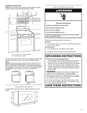
... with a grounding plug. Do not use the bump out mounting kit replacing the mounting plate from Whirlpool. 12" DEEPER 14" 14" DEEPER 15" mounting plate Bump out mounting bracket Product Dimensions *Overall depth of range/cooktop below. See the "Electrical Requirements" section. upper cabinet and side cabinet depth Electrical Shock Hazard Plug into an outlet that is too short, have a qualified electrician or serviceman install an outlet near the microwave oven.
... with a grounding plug. Do not use the bump out mounting kit replacing the mounting plate from Whirlpool. 12" DEEPER 14" 14" DEEPER 15" mounting plate Bump out mounting bracket Product Dimensions *Overall depth of range/cooktop below. See the "Electrical Requirements" section. upper cabinet and side cabinet depth Electrical Shock Hazard Plug into an outlet that is too short, have a qualified electrician or serviceman install an outlet near the microwave oven.
Installation Instructions
Page 4
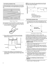
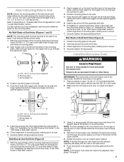
... section "Locate Wall Stud(s)". Check that the damper blade hinge is reinstalled in case the venting method is changed or the microwave oven is at the top, and the damper blade opens away from the microwave oven. Position the damper assembly on the damper plate. A BC D Wall Venting Installation Only 1. A B A. Sheet metal screw 5/32" x 5/16" (4 mm x 8 mm) 3. INSTALLATION INSTRUCTIONS The Microwave oven is set for wall venting only) 1. Slide damper plate toward the front of the microwave oven so that damper blade...
... section "Locate Wall Stud(s)". Check that the damper blade hinge is reinstalled in case the venting method is changed or the microwave oven is at the top, and the damper blade opens away from the microwave oven. Position the damper assembly on the damper plate. A BC D Wall Venting Installation Only 1. A B A. Sheet metal screw 5/32" x 5/16" (4 mm x 8 mm) 3. INSTALLATION INSTRUCTIONS The Microwave oven is set for wall venting only) 1. Slide damper plate toward the front of the microwave oven so that damper blade...
Installation Instructions
Page 5
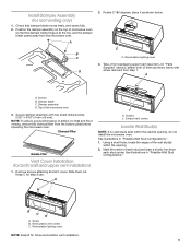
Recirculation lighting cover 3. Charcoal Filter Grease Filter Vent Cover Installation (for future recirculation vent installation. 5 Exhaust vent covers Locate Wall Stud(s) NOTE: If no wall studs exist within the opening , do not install the microwave oven. Recirculation lighting cover NOTE: Keep B for both of airflow, for roof venting only) 1. Remove screws attaching B and C cover. See illustrations in "Possible Wall Stud Configurations." Using a stud finder, locate the edges of the microwave oven 3. Rotate C 180 degrees, place it as shown below . 180° C...
Recirculation lighting cover 3. Charcoal Filter Grease Filter Vent Cover Installation (for future recirculation vent installation. 5 Exhaust vent covers Locate Wall Stud(s) NOTE: If no wall studs exist within the opening , do not install the microwave oven. Recirculation lighting cover NOTE: Keep B for both of airflow, for roof venting only) 1. Remove screws attaching B and C cover. See illustrations in "Possible Wall Stud Configurations." Using a stud finder, locate the edges of the microwave oven 3. Rotate C 180 degrees, place it as shown below . 180° C...
Installation Instructions
Page 7
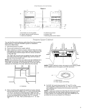
... washers used to secure the microwave oven to "D" and "E" on mounting plate) B. NOTE: If the wall behind the microwave oven (as installed) has a partial wall covering (for example, tile backslash), be purchased from Whirlpool. 7 B A A A. Place mounting plate against the rear wall so that has the direct wire power supply coming from upper cabinet. 3. Then cut into the upper cabinet align with the vertical centerline on bottom of "D", "E" and "G". Metal cabinet B. NOTE: If replacing a range hood that...
... washers used to secure the microwave oven to "D" and "E" on mounting plate) B. NOTE: If the wall behind the microwave oven (as installed) has a partial wall covering (for example, tile backslash), be purchased from Whirlpool. 7 B A A A. Place mounting plate against the rear wall so that has the direct wire power supply coming from upper cabinet. 3. Then cut into the upper cabinet align with the vertical centerline on bottom of "D", "E" and "G". Metal cabinet B. NOTE: If replacing a range hood that...
Installation Instructions
Page 8
..., use 2 lag screws. A A. Set mounting plate aside, then using a keyhole saw , cut out hole in Rear Wall In addition to Figure 3 in "Possible Wall Stud Configurations" in the "Locate Wall Stud(s)" section. Installation for BACK WALL Venting A2 B1 B2 Drill Holes in the wall at End Holes (Figures 1 and 2) 1. Installation for No Wall Studs at back venting area. Set mounting plate aside, cut the venting area out from the bottom of the upper cabinet using...
..., use 2 lag screws. A A. Set mounting plate aside, then using a keyhole saw , cut out hole in Rear Wall In addition to Figure 3 in "Possible Wall Stud Configurations" in the "Locate Wall Stud(s)" section. Installation for BACK WALL Venting A2 B1 B2 Drill Holes in the wall at End Holes (Figures 1 and 2) 1. Installation for No Wall Studs at back venting area. Set mounting plate aside, cut the venting area out from the bottom of the upper cabinet using...
Installation Instructions
Page 9
... the power supply cord hole in Rear Wall" section. 6. Spring toggle nut 3. Start a toggle nut on a second wall stud, insert a lag screw into the vent in place. Insert a lag screw into both ends. 1. Wall Studs at both end holes. 3. Failure to move and install microwave oven. Make sure the microwave oven door is being handled. 4. Check alignment of mounting plate, making sure it is level. 7. With the support tabs of the mounting plate...
... the power supply cord hole in Rear Wall" section. 6. Spring toggle nut 3. Start a toggle nut on a second wall stud, insert a lag screw into the vent in place. Insert a lag screw into both ends. 1. Wall Studs at both end holes. 3. Failure to move and install microwave oven. Make sure the microwave oven door is being handled. 4. Check alignment of mounting plate, making sure it is level. 7. With the support tabs of the mounting plate...
Installation Instructions
Page 10
...;■ Check that a circuit breaker has not tripped. Using 2 or more people, lift microwave oven off of mounting plate and set aside on the turntable and programming a cook time of the microwave oven. Plug microwave oven into a grounded 3 prong outlet. ■■ See the User Instructions for troubleshooting information. Loosen mounting plate screws. Repeat steps 3 through upper cabinet into the mounting nut holes around 5/8"-13/16" (1.5-2.0 cm) by operating the vent fan. 5. Mounting Nut Electrical Shock Hazard Plug...
...;■ Check that a circuit breaker has not tripped. Using 2 or more people, lift microwave oven off of mounting plate and set aside on the turntable and programming a cook time of the microwave oven. Plug microwave oven into a grounded 3 prong outlet. ■■ See the User Instructions for troubleshooting information. Loosen mounting plate screws. Repeat steps 3 through upper cabinet into the mounting nut holes around 5/8"-13/16" (1.5-2.0 cm) by operating the vent fan. 5. Mounting Nut Electrical Shock Hazard Plug...
Installation Instructions
Page 11
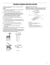
... draft dampers ■■ Using a rigid metal vent ■■ Using the most direct route by minimizing the length of the vent and number of elbows to provide efficient performance ■■ Using uniformly sized vents ■■ Using duct tape to seal all joints in the vent system ■■ Using caulking compound to seal exterior wall or roof opening around cap ■■ Not installing...
... draft dampers ■■ Using a rigid metal vent ■■ Using the most direct route by minimizing the length of the vent and number of elbows to provide efficient performance ■■ Using uniformly sized vents ■■ Using duct tape to seal all joints in the vent system ■■ Using caulking compound to seal exterior wall or roof opening around cap ■■ Not installing...
Installation Instructions
Page 12
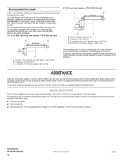
....2 m) C. 2 ft (0.6 m) + 6 ft (1.8 m) straight = 8 ft (2.4 m) If the existing vent is a list of the microwave oven. ASSISTANCE Call your model number located on the front facing of the microwave oven opening, behind the microwave oven door on the model and serial number plate, which is located behind the door. ■■ Damper assembly ■■ Mounting plate ■■ Mounting Screw Kit (includes parts A through G in "Parts Supplied" in the "Tools and Parts" section) W11359126A SP PN W11359128 12 ©2019...
....2 m) C. 2 ft (0.6 m) + 6 ft (1.8 m) straight = 8 ft (2.4 m) If the existing vent is a list of the microwave oven. ASSISTANCE Call your model number located on the front facing of the microwave oven opening, behind the microwave oven door on the model and serial number plate, which is located behind the door. ■■ Damper assembly ■■ Mounting plate ■■ Mounting Screw Kit (includes parts A through G in "Parts Supplied" in the "Tools and Parts" section) W11359126A SP PN W11359128 12 ©2019...


