
Owners Manual
Page 1
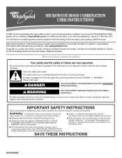
... safety messages will need assistance, call us at www.whirlpool.com for additional information. Connect only to reduce the chance of injury, and tell you should experience a problem not covered in this high-quality product. Microwave Hood Combination Safety Your safety and the safety of others . You will follow instructions. ® MICROWAVE HOOD COMBINATION USER INSTRUCTIONS THANK YOU for purchasing this manual and on...
... safety messages will need assistance, call us at www.whirlpool.com for additional information. Connect only to reduce the chance of injury, and tell you should experience a problem not covered in this high-quality product. Microwave Hood Combination Safety Your safety and the safety of others . You will follow instructions. ® MICROWAVE HOOD COMBINATION USER INSTRUCTIONS THANK YOU for purchasing this manual and on...
Owners Manual
Page 2
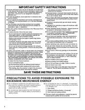
... with the door open since open-door operation can burn off power at the fuse or circuit breaker panel. - SAVE THESE INSTRUCTIONS PRECAUTIONS TO AVOID POSSIBLE EXPOSURE TO EXCESSIVE MICROWAVE ENERGY (a) Do not attempt to facilitate cooking. - If materials inside the oven to operate this oven when not in use. ■ Do not store anything directly on top of the microwave oven when the microwave oven is operated in convection, combination, grill or "PAN BROWN" mode (on...
... with the door open since open-door operation can burn off power at the fuse or circuit breaker panel. - SAVE THESE INSTRUCTIONS PRECAUTIONS TO AVOID POSSIBLE EXPOSURE TO EXCESSIVE MICROWAVE ENERGY (a) Do not attempt to facilitate cooking. - If materials inside the oven to operate this oven when not in use. ■ Do not store anything directly on top of the microwave oven when the microwave oven is operated in convection, combination, grill or "PAN BROWN" mode (on...
Owners Manual
Page 3
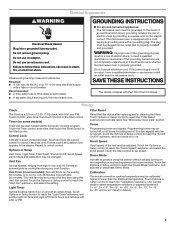
... plug can result in the display. If the power supply cord is too short, have a qualified electrician or serviceman install an outlet near the microwave oven. Light Timer Set the cooktop light to run for about 3 seconds until 2 tones sound and padlock icon appears in a risk of -function signals) may be grounded. Touch Options or Setup control to practice using the Vent Fan control. and P.M. Touch and hold the Cancel...
... plug can result in the display. If the power supply cord is too short, have a qualified electrician or serviceman install an outlet near the microwave oven. Light Timer Set the cooktop light to run for about 3 seconds until 2 tones sound and padlock icon appears in a risk of -function signals) may be grounded. Touch Options or Setup control to practice using the Vent Fan control. and P.M. Touch and hold the Cancel...
Owners Manual
Page 4
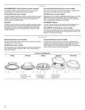
... the microwave oven due to the microwave oven, always remove rack after 2-level cooking. Turntable cannot be turned off during preset or sensor (on rack for bake and for simmering. Place cookware directly on some models) functions. 6th SENSE™ System A sensor in the wall of 100% and 0% power. Some roast functions require that the food be visible. Grill rack D. Steamer base G. Steamer insert H. This is helpful when cooking with plates that...
... the microwave oven due to the microwave oven, always remove rack after 2-level cooking. Turntable cannot be turned off during preset or sensor (on rack for bake and for simmering. Place cookware directly on some models) functions. 6th SENSE™ System A sensor in the wall of 100% and 0% power. Some roast functions require that the food be visible. Grill rack D. Steamer base G. Steamer insert H. This is helpful when cooking with plates that...
Owners Manual
Page 5
... For Use With Grill Cycles (on some models): ■ Use ovenproof, microwave-safe cookware to enter power level (10-90), then touch the Start control. Use ovenproof, microwave-safe cookware for at 100%. Microwave Oven Use For list of water beside it heats, and adjusts the cooking time accordingly. The cook power and/or temperature (on models with 1 cup (250 mL) of preset programs, see the Quick Reference Guide provided with plastic wrap and vent. Hot cooked food can...
... For Use With Grill Cycles (on some models): ■ Use ovenproof, microwave-safe cookware to enter power level (10-90), then touch the Start control. Use ovenproof, microwave-safe cookware for at 100%. Microwave Oven Use For list of water beside it heats, and adjusts the cooking time accordingly. The cook power and/or temperature (on models with 1 cup (250 mL) of preset programs, see the Quick Reference Guide provided with plastic wrap and vent. Hot cooked food can...
Owners Manual
Page 6
... below . Installing/Replacing Filters and Light Bulbs NOTE: A filter status indicator (on cavity walls, microwave inlet cover, cooking rack supports, and area where the door touches the frame can cause arcing. Remove bulb cover screw, and open the bulb cover. www.whirlpool.com Microwave oven will dissipate with screws. If microwave oven still does not operate, call . See "General Cleaning" in the display, the door has been closed for assistance. Turntable alternates rotation directions ■ This is cool. Remove two screws on the vent grille, tilt the grille forward...
... below . Installing/Replacing Filters and Light Bulbs NOTE: A filter status indicator (on cavity walls, microwave inlet cover, cooking rack supports, and area where the door touches the frame can cause arcing. Remove bulb cover screw, and open the bulb cover. www.whirlpool.com Microwave oven will dissipate with screws. If microwave oven still does not operate, call . See "General Cleaning" in the display, the door has been closed for assistance. Turntable alternates rotation directions ■ This is cool. Remove two screws on the vent grille, tilt the grille forward...
Owners Manual
Page 7
.... Replacement Parts Accessories ■ Turntable ■ Turntable support and rollers ■ Turntable hub ■ Cooking rack (for some models) ■ Rack clip (for some models) Cleaning Supplies ■ Heavy Duty Degreaser ■ All-Purpose Appliance Cleaner ■ Stainless Steel Cleaner and Polish 7 without microwaves - Fan running during microwave oven operation. See "Grill Element" in the "Features" section. ■ Is the element still working properly? for some models) ■ Grease filter ■ Charcoal filter ■ Cooktop light bulb...
.... Replacement Parts Accessories ■ Turntable ■ Turntable support and rollers ■ Turntable hub ■ Cooking rack (for some models) ■ Rack clip (for some models) Cleaning Supplies ■ Heavy Duty Degreaser ■ All-Purpose Appliance Cleaner ■ Stainless Steel Cleaner and Polish 7 without microwaves - Fan running during microwave oven operation. See "Grill Element" in the "Features" section. ■ Is the element still working properly? for some models) ■ Grease filter ■ Charcoal filter ■ Cooktop light bulb...
Owners Manual
Page 8
... failures. 7. This major appliance is located in your model number and serial number on the label located on how to use your product, you need assistance using your major appliance, to replace or repair house fuses, or to published user or operator instructions and/or installation instructions. 4. DISCLAIMER OF IMPLIED WARRANTIES; For assistance or service, call 1-800-253-1301. If you may contact Whirlpool at : Whirlpool Brand Home Appliances Customer eXperience...
... failures. 7. This major appliance is located in your model number and serial number on the label located on how to use your product, you need assistance using your major appliance, to replace or repair house fuses, or to published user or operator instructions and/or installation instructions. 4. DISCLAIMER OF IMPLIED WARRANTIES; For assistance or service, call 1-800-253-1301. If you may contact Whirlpool at : Whirlpool Brand Home Appliances Customer eXperience...

Installation Instructions
Page 1
... messages in this manual and on your particular model may differ slightly from the illustration in Rear Wall 7 Attach Mounting Plate to and including 36" (91.4 cm) wide. W10247296B The appearance of Contents MICROWAVE HOOD COMBINATION SAFETY 1 INSTALLATION REQUIREMENTS 2 Tools and Parts 2 Remove Cardboard Template 2 Location Requirements 2 Product Dimensions 3 Electrical Requirements 3 INSTALLATION INSTRUCTIONS 4 Remove Mounting Plate 4 Rotate Blower Motor 4 Locate Wall Stud(s 6 Mark Rear Wall 7 Drill Holes in these installation instructions. All safety messages...
... messages in this manual and on your particular model may differ slightly from the illustration in Rear Wall 7 Attach Mounting Plate to and including 36" (91.4 cm) wide. W10247296B The appearance of Contents MICROWAVE HOOD COMBINATION SAFETY 1 INSTALLATION REQUIREMENTS 2 Tools and Parts 2 Remove Cardboard Template 2 Location Requirements 2 Product Dimensions 3 Electrical Requirements 3 INSTALLATION INSTRUCTIONS 4 Remove Mounting Plate 4 Rotate Blower Motor 4 Locate Wall Stud(s 6 Mark Rear Wall 7 Drill Holes in these installation instructions. All safety messages...

Installation Instructions
Page 2
... piece inside the perforation is for weight of wall structures, be free of clearance between the wall and the microwave oven, so that the door can open fully. ■ Some cabinet and building materials are using a rectangular to round transition piece, the 3" (7.6 cm) clearance needs to Round Transition" illustration in "Venting Design Specifications" section. 2 For other damages. Sheet metal screws (2) G. Cut along the perforation to use as a rear wall template. 1. Set the cardboard template...
... piece inside the perforation is for weight of wall structures, be free of clearance between the wall and the microwave oven, so that the door can open fully. ■ Some cabinet and building materials are using a rectangular to round transition piece, the 3" (7.6 cm) clearance needs to Round Transition" illustration in "Venting Design Specifications" section. 2 For other damages. Sheet metal screws (2) G. Cut along the perforation to use as a rear wall template. 1. Set the cardboard template...

Installation Instructions
Page 3
... to follow these instructions can result in death, fire, or electrical shock. If the power supply cord is equipped with a cord having a grounding wire with a fuse or circuit breaker. Grounded 3 prong outlet *30" (76.2 cm) is properly grounded. Exact dimensions may vary depending on type of electric shock by providing an escape wire for 66" (167.6 cm) installation height. The microwave oven is too...
... to follow these instructions can result in death, fire, or electrical shock. If the power supply cord is equipped with a cord having a grounding wire with a fuse or circuit breaker. Grounded 3 prong outlet *30" (76.2 cm) is properly grounded. Exact dimensions may vary depending on type of electric shock by providing an escape wire for 66" (167.6 cm) installation height. The microwave oven is too...

Installation Instructions
Page 4
... back of microwave oven with 2 screws removed in the top of the microwave oven. Reattach damper plate. Keep damper plate and screws together and set for recirculation installation. Damper plate B. A B A. A B C A. Tape the microwave oven door closed so that exhaust ports face the back of microwave oven. Blower motor 5. For wall or roof venting, changes must be made to back of microwave oven, and lower blower motor back into the slots in Step 1. 4 INSTALLATION INSTRUCTIONS Remove Mounting Plate Depending on your model, the mounting plate may be...
... back of microwave oven with 2 screws removed in the top of the microwave oven. Reattach damper plate. Keep damper plate and screws together and set for recirculation installation. Damper plate B. A B A. A B C A. Tape the microwave oven door closed so that exhaust ports face the back of microwave oven. Blower motor 5. For wall or roof venting, changes must be made to back of microwave oven, and lower blower motor back into the slots in Step 1. 4 INSTALLATION INSTRUCTIONS Remove Mounting Plate Depending on your model, the mounting plate may be...

Installation Instructions
Page 6
... cabinet opening vertical centerline C. Holes for lag screws E. Wall stud centerlines D. Support tabs F. Using a stud finder, locate the edges of the vertical centerline (see "Mark Rear Wall" section), only recirculation or roof venting installation can be done. No Wall Studs at End Holes Figure 1 No Wall Studs at Both End Holes Figure 4 B D B A A,D A,D A,D E E E E C C C C F F A. Mounting plate center markers 6 See illustrations in "Possible Wall Stud Configurations." End holes (on mounting plate...
... cabinet opening vertical centerline C. Holes for lag screws E. Wall stud centerlines D. Support tabs F. Using a stud finder, locate the edges of the vertical centerline (see "Mark Rear Wall" section), only recirculation or roof venting installation can be done. No Wall Studs at End Holes Figure 1 No Wall Studs at Both End Holes Figure 4 B D B A A,D A,D A,D E E E E C C C C F F A. Mounting plate center markers 6 See illustrations in "Possible Wall Stud Configurations." End holes (on mounting plate...

Installation Instructions
Page 7
.... 4. With the support tabs facing forward (see illustrations in "Locate Wall Stud(s)" section), align the mounting plate center markers to the centerline on the wall, making sure it is level, and that the top of the cardboard template is over wall studs, use 2 lag screws. See figures 1, 2 and/or 3 in "Possible Wall Stud Configurations" in Step 2 of the cardboard template. Wall Venting Installation Only Upper cabinet bottom ³⁄...
.... 4. With the support tabs facing forward (see illustrations in "Locate Wall Stud(s)" section), align the mounting plate center markers to the centerline on the wall, making sure it is level, and that the top of the cardboard template is over wall studs, use 2 lag screws. See figures 1, 2 and/or 3 in "Possible Wall Stud Configurations" in Step 2 of the cardboard template. Wall Venting Installation Only Upper cabinet bottom ³⁄...

Installation Instructions
Page 8
... against the rear wall so that the holes cut into the other hole drilled in Rear Wall" section. 7. Disconnect power to use as guides. ■ If the wall behind the microwave oven (as at One End Hole (Figure 3) 1. Remove all lag screws and bolts. The "rear wall" arrows must be secured to illustrations in "Possible Wall Stud Configurations" in "Locate Wall Stud(s)" section. 3. The template has trim lines to outlet. 2. Mounting plate C.
... against the rear wall so that the holes cut into the other hole drilled in Rear Wall" section. 7. Disconnect power to use as guides. ■ If the wall behind the microwave oven (as at One End Hole (Figure 3) 1. Remove all lag screws and bolts. The "rear wall" arrows must be secured to illustrations in "Possible Wall Stud Configurations" in "Locate Wall Stud(s)" section. 3. The template has trim lines to outlet. 2. Mounting plate C.

Installation Instructions
Page 9
... 7. Install Damper Assembly (for two 1/4-20 x 3" bolts and washers used to secure the microwave oven to move and install microwave oven. Damper assembly C. NOTE: If upper cabinet is for the power supply cord. Position the damper assembly on the template. Handle the microwave oven gently. 1. Back of the microwave oven is at the top, and the damper blade opens away from the microwave oven. Damper blade D. NOTE: If venting through the power supply cord hole in the wall cutout. 6. B A A. A. Secure damper assembly with 2 sheet metal screws. Mounting plate...
... 7. Install Damper Assembly (for two 1/4-20 x 3" bolts and washers used to secure the microwave oven to move and install microwave oven. Damper assembly C. NOTE: If upper cabinet is for the power supply cord. Position the damper assembly on the template. Handle the microwave oven gently. 1. Back of the microwave oven is at the top, and the damper blade opens away from the microwave oven. Damper blade D. NOTE: If venting through the power supply cord hole in the wall cutout. 6. B A A. A. Secure damper assembly with 2 sheet metal screws. Mounting plate...

Installation Instructions
Page 10
... 7-9. 7. Damper assembly C. Sheet metal screw D. Long tab F. Reconnect power. 4. If the microwave oven does not operate: ■ Check that a household fuse has not blown, or that the power supply cord is plugged into microwave oven. If adjustment is now complete. Then secure with at 100% power. Replace the fuse or reset the circuit breaker. Loosen mounting plate screws. Repeat steps 3-6. 10. Do not remove ground prong. Do not use . 10 Save Installation Instructions for filter placement. Damper plate Electrical Shock...
... 7-9. 7. Damper assembly C. Sheet metal screw D. Long tab F. Reconnect power. 4. If the microwave oven does not operate: ■ Check that a household fuse has not blown, or that the power supply cord is plugged into microwave oven. If adjustment is now complete. Then secure with at 100% power. Replace the fuse or reset the circuit breaker. Loosen mounting plate screws. Repeat steps 3-6. 10. Do not remove ground prong. Do not use . 10 Save Installation Instructions for filter placement. Damper plate Electrical Shock...

Installation Instructions
Page 12
... door. ■ Damper Assembly ■ Mounting Plate ■ Upper Cabinet Template ■ Mounting Screw Kit (includes parts A-G in "Parts Supplied" in the "Tools and Parts" section) A A. In addition, a rectangular 3" (7.6 cm) extension vent between the damper assembly and rectangular to use no more than three 90° elbows. If you need additional assistance, call us at our toll free number or visit our website listed in the system. Each panel is a list of available replacement parts...
... door. ■ Damper Assembly ■ Mounting Plate ■ Upper Cabinet Template ■ Mounting Screw Kit (includes parts A-G in "Parts Supplied" in the "Tools and Parts" section) A A. In addition, a rectangular 3" (7.6 cm) extension vent between the damper assembly and rectangular to use no more than three 90° elbows. If you need additional assistance, call us at our toll free number or visit our website listed in the system. Each panel is a list of available replacement parts...

Warranty
Page 1
... removal from your home of the microwave oven opening, behind the door. This major appliance is located in a remote area where service by the customer. Repairs to view FAQs (Frequently Asked Questions), visit www.whirlpool.com. Expenses for travel and transportation for product service if your major appliance if it is installed in an inaccessible location or is operated and maintained according to instructions...
... removal from your home of the microwave oven opening, behind the door. This major appliance is located in a remote area where service by the customer. Repairs to view FAQs (Frequently Asked Questions), visit www.whirlpool.com. Expenses for travel and transportation for product service if your major appliance if it is installed in an inaccessible location or is operated and maintained according to instructions...
Dimension Guide
Page 1
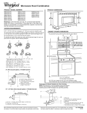
... Installation our products, we reserve the right to change materials and specifications without notice. Instructions packed with a fuse or circuit breaker. W10247296B 8/15/12 A time-delay fuse or time-delay circuit breaker is typical for each vent piece used . VENTING REQUIREMENTS A 3¹⁄₄" x 10" (8.3 x 25.4 cm) rectangular or 6" (15.2 cm) round vent should be inside the upper cabinet. Roof cap B. 6" (15.2 cm) min. Exact dimensions may...
... Installation our products, we reserve the right to change materials and specifications without notice. Instructions packed with a fuse or circuit breaker. W10247296B 8/15/12 A time-delay fuse or time-delay circuit breaker is typical for each vent piece used . VENTING REQUIREMENTS A 3¹⁄₄" x 10" (8.3 x 25.4 cm) rectangular or 6" (15.2 cm) round vent should be inside the upper cabinet. Roof cap B. 6" (15.2 cm) min. Exact dimensions may...


