
Installation Guide
Page 1
Table of Contents MICROWAVE HOOD COMBINATION SAFETY 1 INSTALLATION REQUIREMENTS 2 Tools and Parts 2 Remove Cardboard Template 2 Location Requirements 2 Product Dimensions 3 Electrical Requirements 3 INSTALLATION INSTRUCTIONS 4 Remove Mounting Plate 4 Rotate Blower Motor 4 Locate Wall Stud(s 6 Mark Rear Wall 7 Drill Holes in these installation instructions. These words mean: ...
Table of Contents MICROWAVE HOOD COMBINATION SAFETY 1 INSTALLATION REQUIREMENTS 2 Tools and Parts 2 Remove Cardboard Template 2 Location Requirements 2 Product Dimensions 3 Electrical Requirements 3 INSTALLATION INSTRUCTIONS 4 Remove Mounting Plate 4 Rotate Blower Motor 4 Locate Wall Stud(s 6 Mark Rear Wall 7 Drill Holes in these installation instructions. These words mean: ...
Installation Guide
Page 2
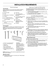
... the cardboard packaging. 2. Special Requirements For Wall Venting Installation Only: ■ Cutout must provide: ■ Minimum installation dimensions. See "Rectangular to separate the template from the top of clearance between the wall and the microwave oven, so that...nuts (2) E. 1/4" x 2" lag screws (2) F. Cut along the perforation to Round Transition" illustration in "Venting Design Specifications" section. 2 See "Installation Dimensions" illustration. ■ Minimum one 2" x 4" (50.8 x 101.6 mm) wood wall stud and minimum 3/8" (10 mm) thickness drywall or plaster/lath...
... the cardboard packaging. 2. Special Requirements For Wall Venting Installation Only: ■ Cutout must provide: ■ Minimum installation dimensions. See "Rectangular to separate the template from the top of clearance between the wall and the microwave oven, so that...nuts (2) E. 1/4" x 2" lag screws (2) F. Cut along the perforation to Round Transition" illustration in "Venting Design Specifications" section. 2 See "Installation Dimensions" illustration. ■ Minimum one 2" x 4" (50.8 x 101.6 mm) wood wall stud and minimum 3/8" (10 mm) thickness drywall or plaster/lath...

Installation Guide
Page 3
... time-delay fuse or time-delay circuit breaker. ■ A separate circuit serving only this microwave oven. WARNING: Improper use an extension cord. Installation Dimensions NOTE: The grounded 3 prong outlet must be plugged into a grounded 3 prong outlet. upper cabinet and side cabinet depth A. 2" x 4" wall stud...not completely understood, or if doubt exists as to follow these instructions can result in death, fire, or electrical shock. Exact dimensions may vary depending on type of electric shock. Do not remove ground prong. The plug must be grounded. SAVE THESE INSTRUCTIONS ...
... time-delay fuse or time-delay circuit breaker. ■ A separate circuit serving only this microwave oven. WARNING: Improper use an extension cord. Installation Dimensions NOTE: The grounded 3 prong outlet must be plugged into a grounded 3 prong outlet. upper cabinet and side cabinet depth A. 2" x 4" wall stud...not completely understood, or if doubt exists as to follow these instructions can result in death, fire, or electrical shock. Exact dimensions may vary depending on type of electric shock. Do not remove ground prong. The plug must be grounded. SAVE THESE INSTRUCTIONS ...

Installation Guide
Page 7
... markers on the wall, making sure it is level, and that its bottom edge is damaged or unusable, measure and mark the wall with the dimensions described in Step 2 of "Locate Wall Stud(s)," and mark at the hole(s) marked in Step 8, and mark. 11. Cardboard template C. Holding the cardboard template in...
... markers on the wall, making sure it is level, and that its bottom edge is damaged or unusable, measure and mark the wall with the dimensions described in Step 2 of "Locate Wall Stud(s)," and mark at the hole(s) marked in Step 8, and mark. 11. Cardboard template C. Holding the cardboard template in...

Installation Guide
Page 8
... (for example, the thickness of the mounting plate facing forward, insert a 1/4-20 x 3" round-head bolt through both end holes. 3. Make sure the 10" (25.4 cm) dimension from the back of the mounting plate. Mounting plate C. Drill a 3/4" (19 mm) hole through the drywall, and finger tighten the bolts to the wall at...
... (for example, the thickness of the mounting plate facing forward, insert a 1/4-20 x 3" round-head bolt through both end holes. 3. Make sure the 10" (25.4 cm) dimension from the back of the mounting plate. Mounting plate C. Drill a 3/4" (19 mm) hole through the drywall, and finger tighten the bolts to the wall at...
Dimension Guide
Page 1
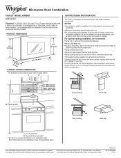
... MODEL NUMBER WMH53520C Electrical: A 120-Volt, 60-Hz, AC-only, 15- PRODUCT DIMENSIONS 17¹⁄₈" (43.5 cm) 16¹⁄₄" (41.3 cm) (1(+.40/1-1c.³06m⁄₈¹c")⁄₈m") 29⁷⁄₈" (76.0 cm) CABINET OPENING DIMENSIONS The grounded...) min. 30" (76.2 cm) min. 30" (76.2 cm) typical* 12" (30.5 cm) min. 14" (35.6 cm) max. Because Whirlpool Corporation policy includes a continuous commitment to open fully. or 20-amp electrical supply with product. It is recommended. NOTES: q Vent materials needed for planning purposes...
... MODEL NUMBER WMH53520C Electrical: A 120-Volt, 60-Hz, AC-only, 15- PRODUCT DIMENSIONS 17¹⁄₈" (43.5 cm) 16¹⁄₄" (41.3 cm) (1(+.40/1-1c.³06m⁄₈¹c")⁄₈m") 29⁷⁄₈" (76.0 cm) CABINET OPENING DIMENSIONS The grounded...) min. 30" (76.2 cm) min. 30" (76.2 cm) typical* 12" (30.5 cm) min. 14" (35.6 cm) max. Because Whirlpool Corporation policy includes a continuous commitment to open fully. or 20-amp electrical supply with product. It is recommended. NOTES: q Vent materials needed for planning purposes...

Dimension Guide
Page 2
... A. Roof cap B. 6" (15.2 cm) min. Wall cap E. 3 " x 10" to 6" (8.3 x 25.4 cm to 15.2 cm) rectangular to improve Dimensions are for Roof Venting NOTE: The minimum 3" (7.6 cm) clearance must be installed to change materials and specifications without notice. Vent extension piece, at least 3" (7.6 cm...) high 2 ft (0.6 m) C A. Because Whirlpool Corporation policy includes a continuous commitment to round transition piece F. Specifications subject to keep the damper from sticking. See the following ...
... A. Roof cap B. 6" (15.2 cm) min. Wall cap E. 3 " x 10" to 6" (8.3 x 25.4 cm to 15.2 cm) rectangular to improve Dimensions are for Roof Venting NOTE: The minimum 3" (7.6 cm) clearance must be installed to change materials and specifications without notice. Vent extension piece, at least 3" (7.6 cm...) high 2 ft (0.6 m) C A. Because Whirlpool Corporation policy includes a continuous commitment to round transition piece F. Specifications subject to keep the damper from sticking. See the following ...


