Installation Instructions
Page 2
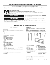
... on model, charcoal filters may be included. Power supply cord bushing (1) ■■ Aluminum grease filters H. For other types of wall structures, be sure to back of microwave oven) E. 1/4" x 2" lag screws (2) ■■ Cardboard template (part of F. #6 x 3/8" Sheet metal screws (2) packaging) or wall template G. Washers (2) D. 3/16" toggle nuts (2) ■■ Mounting plate (attached to use appropriate fasteners. Materials Needed Standard fittings for wood studs. Read and follow the instructions provided with any tools listed...
... on model, charcoal filters may be included. Power supply cord bushing (1) ■■ Aluminum grease filters H. For other types of wall structures, be sure to back of microwave oven) E. 1/4" x 2" lag screws (2) ■■ Cardboard template (part of F. #6 x 3/8" Sheet metal screws (2) packaging) or wall template G. Washers (2) D. 3/16" toggle nuts (2) ■■ Mounting plate (attached to use appropriate fasteners. Materials Needed Standard fittings for wood studs. Read and follow the instructions provided with any tools listed...
Installation Instructions
Page 3
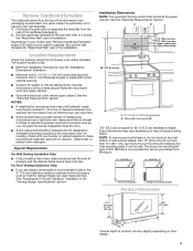
....5 cm) min. 14" (35.6 cm) max. Installation Dimensions NOTE: The grounded 3 prong outlet must provide: ■■ Minimum installation dimensions. Set the cardboard template to the side and refer to withstand the heat produced by the microwave oven for "Mark Rear Wall" part of any obstructions so that the door can open fully. ■■ Some models have a pocket handle. Remove Cardboard Template The cardboard piece from the top of range/cooktop below.
....5 cm) min. 14" (35.6 cm) max. Installation Dimensions NOTE: The grounded 3 prong outlet must provide: ■■ Minimum installation dimensions. Set the cardboard template to the side and refer to withstand the heat produced by the microwave oven for "Mark Rear Wall" part of any obstructions so that the door can open fully. ■■ Some models have a pocket handle. Remove Cardboard Template The cardboard piece from the top of range/cooktop below.
Installation Instructions
Page 4
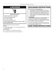
... INSTRUCTIONS 4 Do not use an extension cord. In the event of an electrical short circuit, grounding reduces the risk of electric shock. The microwave oven is equipped with a cord having a grounding wire with a fuse or circuit breaker Recommended: ■■ A time-delay fuse or time-delay circuit breaker ■■ A separate circuit serving only this microwave oven GROUNDING INSTRUCTIONS For all governing codes and ordinances. WARNING: Improper use an extension cord. If the power...
... INSTRUCTIONS 4 Do not use an extension cord. In the event of an electrical short circuit, grounding reduces the risk of electric shock. The microwave oven is equipped with a cord having a grounding wire with a fuse or circuit breaker Recommended: ■■ A time-delay fuse or time-delay circuit breaker ■■ A separate circuit serving only this microwave oven GROUNDING INSTRUCTIONS For all governing codes and ordinances. WARNING: Improper use an extension cord. If the power...
Installation Instructions
Page 5
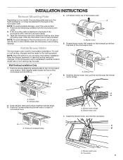
... mounting plate is attached to the back of the microwave oven. Exhaust Port 6. Blower motor wire 7. Insert the blower motor wire into the connector. Remove any remaining contents from the microwave oven cavity. 2. Rotate Blower Motor The microwave oven is being handled. NOTE: Skip this section if you are using recirculation installation. Rotate blower motor 180 degree so that the door does not swing open while the microwave oven is set aside. 3. A Wall Venting Installation Only 1. Screws B. Blower motor...
... mounting plate is attached to the back of the microwave oven. Exhaust Port 6. Blower motor wire 7. Insert the blower motor wire into the connector. Remove any remaining contents from the microwave oven cavity. 2. Rotate Blower Motor The microwave oven is being handled. NOTE: Skip this section if you are using recirculation installation. Rotate blower motor 180 degree so that the door does not swing open while the microwave oven is set aside. 3. A Wall Venting Installation Only 1. Screws B. Blower motor...
Installation Instructions
Page 6
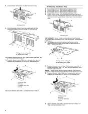
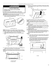
... poor. 6. Using diagonal wire cutting pliers, gently snip out the rectangular vent covers on the damper plate removed in Step 1. A B C D A. Repeat Step 1 from "Wall Venting Installation Only." 4. Roof Venting Installation Only 1. Reattach blower motor to back of microwave oven with the 2 screws removed in the top of the microwave oven. NOTE: If blower motor is not positioned with 2 screws removed in the top of microwave oven with 2 screws removed in Step 1 at the perforations. A A. Damper vent covers 10. Exhaust port IMPORTANT...
... poor. 6. Using diagonal wire cutting pliers, gently snip out the rectangular vent covers on the damper plate removed in Step 1. A B C D A. Repeat Step 1 from "Wall Venting Installation Only." 4. Roof Venting Installation Only 1. Reattach blower motor to back of microwave oven with the 2 screws removed in the top of the microwave oven. NOTE: If blower motor is not positioned with 2 screws removed in the top of microwave oven with 2 screws removed in Step 1 at the perforations. A A. Damper vent covers 10. Exhaust port IMPORTANT...
Installation Instructions
Page 7
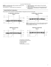
... center of preferred installation configurations with the mounting plate. Mounting plate center markers 7 Locate Wall Stud(s) NOTE: If no wall studs exist within the opening , do not install the microwave oven. Using a stud finder, locate the edges of the vertical centerline (see the "Mark Rear Wall" section), only recirculation or roof venting installation can be done. Cabinet opening vertical centerline C. Holes for lag screws E. See illustrations in "Possible Wall Stud Configurations." 1. Possible...
... center of preferred installation configurations with the mounting plate. Mounting plate center markers 7 Locate Wall Stud(s) NOTE: If no wall studs exist within the opening , do not install the microwave oven. Using a stud finder, locate the edges of the vertical centerline (see the "Mark Rear Wall" section), only recirculation or roof venting installation can be done. Cabinet opening vertical centerline C. Holes for lag screws E. See illustrations in "Possible Wall Stud Configurations." 1. Possible...
Installation Instructions
Page 8
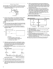
....2 cm) 6" (15.2 cm) 8. Cut a 3/4" (1.9 cm) hole in Step 4. Front edge of the cabinet. ■■ If the cardboard template or wall template is level with each be on both holes in Step 2 of the cutout area. 14. With the support tabs facing forward (see illustrations in the "Locate Wall Stud(s)" section), align the mounting plate center markers to the wall stud centerline(s). The blackened...
....2 cm) 6" (15.2 cm) 8. Cut a 3/4" (1.9 cm) hole in Step 4. Front edge of the cabinet. ■■ If the cardboard template or wall template is level with each be on both holes in Step 2 of the cutout area. 14. With the support tabs facing forward (see illustrations in the "Locate Wall Stud(s)" section), align the mounting plate center markers to the wall stud centerline(s). The blackened...
Installation Instructions
Page 9
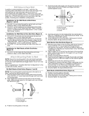
.... With the support tabs of "Installation for Wall Stud at Both End Holes (Figure 4) 1. If installing on a second wall stud, insert a lag screw into wall stud(s) in Step 2 of the mounting plate facing forward, insert a 3/16-24 x 3" round-head bolt through the wall and to open . Wall Studs at One End Hole" in the "Drill Holes in Rear Wall" section. 7. Insert lag screws into the...
.... With the support tabs of "Installation for Wall Stud at Both End Holes (Figure 4) 1. If installing on a second wall stud, insert a lag screw into wall stud(s) in Step 2 of the mounting plate facing forward, insert a 3/16-24 x 3" round-head bolt through the wall and to open . Wall Studs at One End Hole" in the "Drill Holes in Rear Wall" section. 7. Insert lag screws into the...
Installation Instructions
Page 10
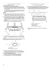
... at one corner of the microwave oven so that it , trim the template edges so that the damper blade hinge is for wall venting only) 1. For Roof Venting Installation Only: 7. Cut 3/4" (1.9 cm) hole at points "D" and "E" on the template is metal, the supply cord bushing needs to be sure the "Rear Wall" arrows align to the upper cabinet. Install Damper Assembly (for the power supply cord. A B C D Upper-cabinet template D 10" (25.4 cm) F E 10...
... at one corner of the microwave oven so that it , trim the template edges so that the damper blade hinge is for wall venting only) 1. For Roof Venting Installation Only: 7. Cut 3/4" (1.9 cm) hole at points "D" and "E" on the template is metal, the supply cord bushing needs to be sure the "Rear Wall" arrows align to the upper cabinet. Install Damper Assembly (for the power supply cord. A B C D Upper-cabinet template D 10" (25.4 cm) F E 10...
Installation Instructions
Page 11
... microwave oven gently. 1. Remove the 2 packing spacers from the top of mounting plate, and set aside on each 1/4-20 x 3" flat-head bolt and place inside upper cabinet near the 3/8" (10 mm) holes. 3. With the microwave oven centered, and with step 2. 2. A 4. Bolts 11 Make sure the microwave oven door is the heavy side. NOTE: If microwave oven does not need to be adjusted, skip steps 7 through the power...
... microwave oven gently. 1. Remove the 2 packing spacers from the top of mounting plate, and set aside on each 1/4-20 x 3" flat-head bolt and place inside upper cabinet near the 3/8" (10 mm) holes. 3. With the microwave oven centered, and with step 2. 2. A 4. Bolts 11 Make sure the microwave oven door is the heavy side. NOTE: If microwave oven does not need to be adjusted, skip steps 7 through the power...
Installation Instructions
Page 12
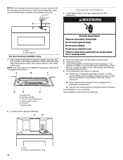
.... Plug microwave oven into a grounded 3 prong outlet. A B A. Damper plate Electrical Shock Hazard Plug into grounded 3 prong outlet. 3. Save Installation Instructions for troubleshooting information. Refer to damper assembly. Do not remove ground prong. Replace the fuse or reset the circuit breaker. Connect vent to the User Instructions for filter placement. Install filters. Long tab F. The installation is not positioned as shown. Vent B. Then tighten with #6 x 3/8" sheet metal screw. WARNING A. Insert damper assembly through the cabinet cutout so...
.... Plug microwave oven into a grounded 3 prong outlet. A B A. Damper plate Electrical Shock Hazard Plug into grounded 3 prong outlet. 3. Save Installation Instructions for troubleshooting information. Refer to damper assembly. Do not remove ground prong. Replace the fuse or reset the circuit breaker. Connect vent to the User Instructions for filter placement. Install filters. Long tab F. The installation is not positioned as shown. Vent B. Then tighten with #6 x 3/8" sheet metal screw. WARNING A. Insert damper assembly through the cabinet cutout so...
Installation Instructions
Page 13
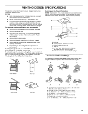
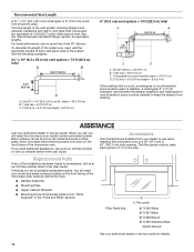
...;■ Using uniformly sized vents. ■■ Using duct tape to -round transition piece so that the damper can open fully. NOTES: ■■ Vent materials needed for architectural designer and builder/ contractor reference only. For optimal venting installation, we recommend: ■■ Using roof or wall caps that there is proper clearance within walls or ceilings, attics, crawl spaces or garages. VENTING DESIGN SPECIFICATIONS This...
...;■ Using uniformly sized vents. ■■ Using duct tape to -round transition piece so that the damper can open fully. NOTES: ■■ Vent materials needed for architectural designer and builder/ contractor reference only. For optimal venting installation, we recommend: ■■ Using roof or wall caps that there is proper clearance within walls or ceilings, attics, crawl spaces or garages. VENTING DESIGN SPECIFICATIONS This...
Installation Instructions
Page 14
... vent is located behind the door. ■■ Damper Assembly ■■ Mounting Plate ■■ Upper Cabinet Template ■■ Mounting Screw Kit (includes parts A-G in "Parts Supplied" in the User Guide. If you need your dealer to be replaced, call , you will need , add the equivalent lengths of each vent piece used in a 36" (91.4 cm) or 42" (106.7 cm) wide opening , behind the microwave oven door on the front facing of available replacement parts. Replacement Parts...
... vent is located behind the door. ■■ Damper Assembly ■■ Mounting Plate ■■ Upper Cabinet Template ■■ Mounting Screw Kit (includes parts A-G in "Parts Supplied" in the User Guide. If you need your dealer to be replaced, call , you will need , add the equivalent lengths of each vent piece used in a 36" (91.4 cm) or 42" (106.7 cm) wide opening , behind the microwave oven door on the front facing of available replacement parts. Replacement Parts...
Specification Sheet
Page 1
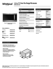
General Features & Properties Turntable On/Off Option 3-Speed, 300 CFM Motor Class Fingerprint Resistant Dishwasher-Safe Turntable Plate Microwave Presets Add 30 Seconds Option Electronic Touch Controls Adjustable Cooktop Lighting Hidden Vent Electrical Details Amps 16 Volts 120 Technical Details Microwave Type CFMs Lighting Type Number of your food and adjusts the cook time as needed. NOTE: Dimensions are for planning purposes only. Specifications subject to change without notice. ®/™ © 2020. Over...
General Features & Properties Turntable On/Off Option 3-Speed, 300 CFM Motor Class Fingerprint Resistant Dishwasher-Safe Turntable Plate Microwave Presets Add 30 Seconds Option Electronic Touch Controls Adjustable Cooktop Lighting Hidden Vent Electrical Details Amps 16 Volts 120 Technical Details Microwave Type CFMs Lighting Type Number of your food and adjusts the cook time as needed. NOTE: Dimensions are for planning purposes only. Specifications subject to change without notice. ®/™ © 2020. Over...


