Installation Guide
Page 1
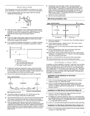
... HOOD COMBINATION SAFETY Your safety and the safety of Contents MICROWAVE HOOD COMBINATION SAFETY 1 INSTALLATION REQUIREMENTS 2 Tools and Parts 2 Remove Cardboard Template 2 Location Requirements 2 Product Dimensions 3 Electrical Requirements 3 INSTALLATION INSTRUCTIONS 4 Remove Mounting Plate 4 Rotate Blower Motor 4 Locate Wall Stud(s 6 Mark Rear Wall 7 Drill Holes in these installation instructions. MICROWAVE HOOD COMBINATION...
... HOOD COMBINATION SAFETY Your safety and the safety of Contents MICROWAVE HOOD COMBINATION SAFETY 1 INSTALLATION REQUIREMENTS 2 Tools and Parts 2 Remove Cardboard Template 2 Location Requirements 2 Product Dimensions 3 Electrical Requirements 3 INSTALLATION INSTRUCTIONS 4 Remove Mounting Plate 4 Rotate Blower Motor 4 Locate Wall Stud(s 6 Mark Rear Wall 7 Drill Holes in these installation instructions. MICROWAVE HOOD COMBINATION...
Installation Guide
Page 2
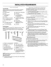
... fasteners. Special Requirements For Wall Venting Installation Only: ■■ Cutout must provide: ■■ Minimum installation dimensions. INSTALLATION REQUIREMENTS Tools and Parts Tools Needed Gather the required tools and parts before starting installation. Z\v" x 2" lag...D E FG H A. 3/16-24 x 3" round-head bolts (2) B. 1/4-20 x 3" flat-head bolts (2) C. Damper assembly (for cooking. See "Installation Dimensions" illustration. ■■ Minimum one 2" x 4" (50.8 x 101.6 mm) wood wall stud and minimum C\," (10 mm) thickness drywall or plaster/lath within...
... fasteners. Special Requirements For Wall Venting Installation Only: ■■ Cutout must provide: ■■ Minimum installation dimensions. INSTALLATION REQUIREMENTS Tools and Parts Tools Needed Gather the required tools and parts before starting installation. Z\v" x 2" lag...D E FG H A. 3/16-24 x 3" round-head bolts (2) B. 1/4-20 x 3" flat-head bolts (2) C. Damper assembly (for cooking. See "Installation Dimensions" illustration. ■■ Minimum one 2" x 4" (50.8 x 101.6 mm) wood wall stud and minimum C\," (10 mm) thickness drywall or plaster/lath within...
Installation Guide
Page 3
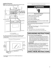
...grounding plug can result in a risk of range/ cooktop below. WARNING: Improper use an extension cord. A. 2" x 4" wall stud B. Exact dimensions may vary depending on door design. SAVE THESE INSTRUCTIONS 3 See "Electrical Requirements" section. GROUNDING INSTRUCTIONS I For all governing codes and ordinances. The ...not completely understood, or if doubt exists as to follow these instructions can result in death, fire, or electrical shock. Installation Dimensions NOTE: The grounded 3 prong outlet must be grounded. Do not use an extension cord. If the power supply cord is ...
...grounding plug can result in a risk of range/ cooktop below. WARNING: Improper use an extension cord. A. 2" x 4" wall stud B. Exact dimensions may vary depending on door design. SAVE THESE INSTRUCTIONS 3 See "Electrical Requirements" section. GROUNDING INSTRUCTIONS I For all governing codes and ordinances. The ...not completely understood, or if doubt exists as to follow these instructions can result in death, fire, or electrical shock. Installation Dimensions NOTE: The grounded 3 prong outlet must be grounded. Do not use an extension cord. If the power supply cord is ...
Installation Guide
Page 7
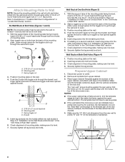
...;₈" (35.9 cm) from the centerline. 5. Align the center markers on the cardboard template (carton top cap) to the centerline on a level line with the dimensions described in Step 3 of "Mark Rear Wall." NOTES: ■■ If the front edge of the upper cabinet is lower than the back edge, lower...
...;₈" (35.9 cm) from the centerline. 5. Align the center markers on the cardboard template (carton top cap) to the centerline on a level line with the dimensions described in Step 3 of "Mark Rear Wall." NOTES: ■■ If the front edge of the upper cabinet is lower than the back edge, lower...
Installation Guide
Page 8
... with toggle nuts through the drywall, and finger tighten the bolt to outlet. 2. Place Upper Cabinet Template against drywall. Make sure the 10" (25.4 cm) dimension from upper cabinet. 3. Wall Stud at Both End Holes (Figure 4) 1. Prepare Upper Cabinet 1. A C B D A. 3/16-24 x 3" round-head bolt B. Check alignment of mounting plate. 2. B A C A. 3/16-24...
... with toggle nuts through the drywall, and finger tighten the bolt to outlet. 2. Place Upper Cabinet Template against drywall. Make sure the 10" (25.4 cm) dimension from upper cabinet. 3. Wall Stud at Both End Holes (Figure 4) 1. Prepare Upper Cabinet 1. A C B D A. 3/16-24 x 3" round-head bolt B. Check alignment of mounting plate. 2. B A C A. 3/16-24...
Dimension Guide
Page 1
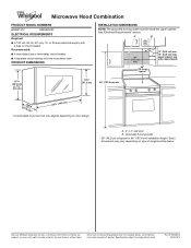
...* 12" (30.5 cm) min. 14" (35.6 cm) max. A. 2" x 4" wall stud B. Dimensions are for 66" (167.6 cm) installation height. Microwave Hood Combination PRODUCT MODEL NUMBERS WMH31017 WMH32519F ELECTRICAL REQUIREMENTS Required: ■■ A 120 volt, 60 Hz, AC only, 15- or 20-amp electrical ...supply with product. PRODUCT DIMENSIONS INSTALLATION DIMENSIONS NOTE: The grounded 3 prong outlet must be inside the upper cabinet. Because Whirlpool Corporation ...
...* 12" (30.5 cm) min. 14" (35.6 cm) max. A. 2" x 4" wall stud B. Dimensions are for 66" (167.6 cm) installation height. Microwave Hood Combination PRODUCT MODEL NUMBERS WMH31017 WMH32519F ELECTRICAL REQUIREMENTS Required: ■■ A 120 volt, 60 Hz, AC only, 15- or 20-amp electrical ...supply with product. PRODUCT DIMENSIONS INSTALLATION DIMENSIONS NOTE: The grounded 3 prong outlet must be inside the upper cabinet. Because Whirlpool Corporation ...


