Owners Manual
Page 3
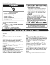
... to avoid unintended start. Do not use an adapter. or 20-amp electrical supply with Industry Canada ICES-001. The microwave oven is equipped with Part 18 of the vent grille, remove them before using the microwave oven. Control Lock Activate to deactivate. Repeat to practice using the Vent Fan control...
... to avoid unintended start. Do not use an adapter. or 20-amp electrical supply with Industry Canada ICES-001. The microwave oven is equipped with Part 18 of the vent grille, remove them before using the microwave oven. Control Lock Activate to deactivate. Repeat to practice using the Vent Fan control...
Owners Manual
Page 5
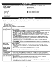
...or more recommendations that may be purchased separately. Mississauga, Ontario L5N 0B7 Please include a daytime phone number in the bullets below : Whirlpool Brand Home Appliances Customer eXperience Centre 200 - 6750 Century Ave. On some models) is OFF. ■■ Packing spacers: Make ...on and off to the warranty page in the "Microwave Oven Care" section. ACCESSORIES Following is a list of the cycle. Replacement Parts Cleaning Supplies ■■ Turntable ■■ Heavy-duty degreaser ■■ Turntable support and rollers ■■ affresh&#...
...or more recommendations that may be purchased separately. Mississauga, Ontario L5N 0B7 Please include a daytime phone number in the bullets below : Whirlpool Brand Home Appliances Customer eXperience Centre 200 - 6750 Century Ave. On some models) is OFF. ■■ Packing spacers: Make ...on and off to the warranty page in the "Microwave Oven Care" section. ACCESSORIES Following is a list of the cycle. Replacement Parts Cleaning Supplies ■■ Turntable ■■ Heavy-duty degreaser ■■ Turntable support and rollers ■■ affresh&#...
Owners Manual
Page 6
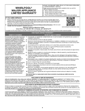
...high moisture or humidity or exposure to product failure. This limited warranty is not available. The cost of non-genuine Whirlpool parts or accessories. EXCLUSION OF INCIDENTAL AND CONSEQUENTIAL DAMAGES YOUR SOLE AND EXCLUSIVE REMEDY UNDER THIS LIMITED WARRANTY SHALL BE PRODUCT ...islands, countertops, drywall, etc.) that vary from state to state or province to : Whirlpool Customer eXperience Center www.whirlpool.com/product_help In the U.S.A., call 1-800-807-6777. Service or parts for warranty service to province. 11/14 6 Some states and provinces do not allow limitations...
...high moisture or humidity or exposure to product failure. This limited warranty is not available. The cost of non-genuine Whirlpool parts or accessories. EXCLUSION OF INCIDENTAL AND CONSEQUENTIAL DAMAGES YOUR SOLE AND EXCLUSIVE REMEDY UNDER THIS LIMITED WARRANTY SHALL BE PRODUCT ...islands, countertops, drywall, etc.) that vary from state to state or province to : Whirlpool Customer eXperience Center www.whirlpool.com/product_help In the U.S.A., call 1-800-807-6777. Service or parts for warranty service to province. 11/14 6 Some states and provinces do not allow limitations...
Installation Instructions
Page 1
... Damper Assembly 9 Install the Microwave Oven 9 Complete Installation 10 VENTING DESIGN SPECIFICATIONS 11 ASSISTANCE 12 Replacement Parts 12 Accessories 12 MICROWAVE HOOD COMBINATION SAFETY Your safety and the safety of others . Table of your ...INSTRUCTIONS This product is suitable for further notes. The appearance of Contents MICROWAVE HOOD COMBINATION SAFETY 1 INSTALLATION REQUIREMENTS 2 Tools and Parts 2 Remove Cardboard Template 2 Location Requirements 2 Product Dimensions 3 Electrical Requirements 3 INSTALLATION INSTRUCTIONS 4 Remove Mounting Plate 4 Rotate...
... Damper Assembly 9 Install the Microwave Oven 9 Complete Installation 10 VENTING DESIGN SPECIFICATIONS 11 ASSISTANCE 12 Replacement Parts 12 Accessories 12 MICROWAVE HOOD COMBINATION SAFETY Your safety and the safety of others . Table of your ...INSTRUCTIONS This product is suitable for further notes. The appearance of Contents MICROWAVE HOOD COMBINATION SAFETY 1 INSTALLATION REQUIREMENTS 2 Tools and Parts 2 Remove Cardboard Template 2 Location Requirements 2 Product Dimensions 3 Electrical Requirements 3 INSTALLATION INSTRUCTIONS 4 Remove Mounting Plate 4 Rotate...
Installation Instructions
Page 2
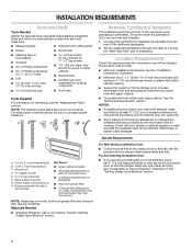
... (2) B. Z\v-20 x 3" flat-head bolts (2) C. Washers (2) D. Sheet metal screws (2) G. See User Instructions.) NOTE: Depending on reordering, see the "Replacement Parts" section. See the "Installation Dimensions" illustration. ■■ Minimum one 2" x 4" (50.8 x 101.6 mm) wood wall stud and minimum C\," (10 mm...9632; Caulking gun and weatherproof caulking compound ■■ C\v" (19 mm) hole saw ■■ Duct tape Parts Supplied For information on model, aluminum grease filter and charcoal filter may not be included. Special Requirements For Wall Venting Installation...
... (2) B. Z\v-20 x 3" flat-head bolts (2) C. Washers (2) D. Sheet metal screws (2) G. See User Instructions.) NOTE: Depending on reordering, see the "Replacement Parts" section. See the "Installation Dimensions" illustration. ■■ Minimum one 2" x 4" (50.8 x 101.6 mm) wood wall stud and minimum C\," (10 mm...9632; Caulking gun and weatherproof caulking compound ■■ C\v" (19 mm) hole saw ■■ Duct tape Parts Supplied For information on model, aluminum grease filter and charcoal filter may not be included. Special Requirements For Wall Venting Installation...
Installation Instructions
Page 8
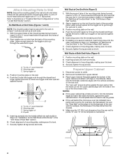
..." in the "Drill Holes in Rear Wall" section. 6. Push the 2 bolts with toggle nuts through the drywall and finger tighten the bolts to the thickest part of "Installation for Wall Stud at End Holes" in the "Drill Holes in Rear Wall" section. 7. Place Upper Cabinet Template against drywall. With the support...
..." in the "Drill Holes in Rear Wall" section. 6. Push the 2 bolts with toggle nuts through the drywall and finger tighten the bolts to the thickest part of "Installation for Wall Stud at End Holes" in the "Drill Holes in Rear Wall" section. 7. Place Upper Cabinet Template against drywall. With the support...
Installation Instructions
Page 12
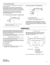
... vent. Both numbers can be replaced, call us at our toll-free number listed in the system. The filler panels come in the "Tools and Parts" section) A A. One 3¹⁄₄" x 10" (8.3 x 25.4 cm) 90° elbow = 25 ft (7.6 m) B. 1 wall cap = 40 ft (12.2 m) C. 2 ..., behind the door. ■■ Damper assembly ■■ Mounting plate ■■ Upper cabinet template ■■ Mounting Screw Kit (includes parts A through G in "Parts Supplied" in pairs. See the following examples: 3¹⁄₄" x 10" (8.3 x 25.4 cm) vent system = 73 ft (22.2 m) ...
... vent. Both numbers can be replaced, call us at our toll-free number listed in the system. The filler panels come in the "Tools and Parts" section) A A. One 3¹⁄₄" x 10" (8.3 x 25.4 cm) 90° elbow = 25 ft (7.6 m) B. 1 wall cap = 40 ft (12.2 m) C. 2 ..., behind the door. ■■ Damper assembly ■■ Mounting plate ■■ Upper cabinet template ■■ Mounting Screw Kit (includes parts A through G in "Parts Supplied" in pairs. See the following examples: 3¹⁄₄" x 10" (8.3 x 25.4 cm) vent system = 73 ft (22.2 m) ...


