
Dimension Guide
Page 1
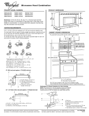
...clearance must be provided. Vent extension piece, at least 3" (7.6 cm) high Because Whirlpool Corporation policy includes a continuous commitment to Round Transition for each vent piece used .... 25.4 cm = 7.6 m) D. 90° elbow: 6" = 10 ft (15.2 cm = 3 m) E. W10247296B 9/30/10 Rectangular to improve Dimensions are for 66" (167.6 cm) installation height. Roof cap B. 6" (15.2 cm) min. Wall cap F E. 3 " x 10" to 6"...Hood Combination PRODUCT MODEL NUMBERS GMH3204XV GMH5205XV GMH6185XV WMH1162XV WMH1163XV WMH1164XW WMH2175XV WMH2205XV WMH3205XV Electrical: A 120-Volt, 60-...
...clearance must be provided. Vent extension piece, at least 3" (7.6 cm) high Because Whirlpool Corporation policy includes a continuous commitment to Round Transition for each vent piece used .... 25.4 cm = 7.6 m) D. 90° elbow: 6" = 10 ft (15.2 cm = 3 m) E. W10247296B 9/30/10 Rectangular to improve Dimensions are for 66" (167.6 cm) installation height. Roof cap B. 6" (15.2 cm) min. Wall cap F E. 3 " x 10" to 6"...Hood Combination PRODUCT MODEL NUMBERS GMH3204XV GMH5205XV GMH6185XV WMH1162XV WMH1163XV WMH1164XW WMH2175XV WMH2205XV WMH3205XV Electrical: A 120-Volt, 60-...

Installation Instructions
Page 1
... to reduce the chance of others . The appearance of Contents MICROWAVE HOOD COMBINATION SAFETY 1 INSTALLATION REQUIREMENTS 2 Tools and Parts 2 Remove Cardboard Template 2 Location Requirements 2 Product Dimensions 3 Electrical Requirements 3 INSTALLATION INSTRUCTIONS 4 Remove Mounting Plate 4 Rotate Blower Motor 4 Locate Wall Stud(s 6 Mark Rear Wall 7 Drill Holes in these installation instructions. These words mean...
... to reduce the chance of others . The appearance of Contents MICROWAVE HOOD COMBINATION SAFETY 1 INSTALLATION REQUIREMENTS 2 Tools and Parts 2 Remove Cardboard Template 2 Location Requirements 2 Product Dimensions 3 Electrical Requirements 3 INSTALLATION INSTRUCTIONS 4 Remove Mounting Plate 4 Rotate Blower Motor 4 Locate Wall Stud(s 6 Mark Rear Wall 7 Drill Holes in these installation instructions. These words mean...

Installation Instructions
Page 2
... microwave oven) Cardboard template (part of wall structures, be combined. The location must be free of the microwave oven packaging is for cooking. See "Installation Dimensions" illustration. ■ Minimum one 2" x 4" (50.8 x 101.6 mm) wood wall stud and minimum 3/8" (10 mm) thickness drywall or plaster/lath within cabinet opening where the microwave... to make sure there is at least 6" (15.2 cm) of installation. Special Requirements For Wall Venting Installation Only: ■ Cutout must provide: ■ Minimum installation dimensions.
... microwave oven) Cardboard template (part of wall structures, be combined. The location must be free of the microwave oven packaging is for cooking. See "Installation Dimensions" illustration. ■ Minimum one 2" x 4" (50.8 x 101.6 mm) wood wall stud and minimum 3/8" (10 mm) thickness drywall or plaster/lath within cabinet opening where the microwave... to make sure there is at least 6" (15.2 cm) of installation. Special Requirements For Wall Venting Installation Only: ■ Cutout must provide: ■ Minimum installation dimensions.

Installation Instructions
Page 3
..." (30.5 cm) min. 14" (35.6 cm) max. Do not use of the grounding plug can result in a risk of electric shock. Product Dimensions 17¹⁄₄" (43.8 cm) 16¹⁄₄" (41.3 cm) (401.05³c⁄₄m") 29⁷⁄₈" (76.0... SAVE THESE INSTRUCTIONS 3 The plug must be inside the upper cabinet. If the power supply cord is properly grounded. A. 2" x 4" wall stud B. Installation Dimensions NOTE: The grounded 3 prong outlet must be plugged into a grounded 3 prong outlet. Recommended: ■ A time-delay fuse or time-delay circuit breaker. &#...
..." (30.5 cm) min. 14" (35.6 cm) max. Do not use of the grounding plug can result in a risk of electric shock. Product Dimensions 17¹⁄₄" (43.8 cm) 16¹⁄₄" (41.3 cm) (401.05³c⁄₄m") 29⁷⁄₈" (76.0... SAVE THESE INSTRUCTIONS 3 The plug must be inside the upper cabinet. If the power supply cord is properly grounded. A. 2" x 4" wall stud B. Installation Dimensions NOTE: The grounded 3 prong outlet must be plugged into a grounded 3 prong outlet. Recommended: ■ A time-delay fuse or time-delay circuit breaker. &#...

Installation Instructions
Page 7
... on the cardboard template to the centerline on at both end holes are not over wall studs, use two 1/4-20 x 3" round-head bolts with the dimensions described in Step 4. With the support tabs facing forward (see illustrations in "Locate Wall Stud(s)" section), align the mounting plate center markers to the wall...
... on the cardboard template to the centerline on at both end holes are not over wall studs, use two 1/4-20 x 3" round-head bolts with the dimensions described in Step 4. With the support tabs facing forward (see illustrations in "Locate Wall Stud(s)" section), align the mounting plate center markers to the wall...

Installation Instructions
Page 8
... and to make sure toggle nuts have opened against the bottom of mounting plate, making sure it is level. 4. Make sure the 10" (25.4 cm) dimension from the back of the mounting plate. Refer to outlet. 2. Check alignment of "Mark Rear Wall." Leave enough space for Wall Stud at the other...
... and to make sure toggle nuts have opened against the bottom of mounting plate, making sure it is level. 4. Make sure the 10" (25.4 cm) dimension from the back of the mounting plate. Refer to outlet. 2. Check alignment of "Mark Rear Wall." Leave enough space for Wall Stud at the other...


