Dimension Guide
Page 1
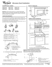
... the damper can open freely and fully. Exact dimensions may vary depending on type of the system you need, add the equivalent length for 66" (167.6 cm) installation height. Instructions packed with a fuse or circuit breaker. To calculate the length of range/cooktop below. Two 90° elbows = 20 ft (6.1 m) B. 1 wall cap = 40 ft (12.2 m) C. 1 rectangular to round transition piece F. A 2 ft (0.6 m) C A. Specifications...
... the damper can open freely and fully. Exact dimensions may vary depending on type of the system you need, add the equivalent length for 66" (167.6 cm) installation height. Instructions packed with a fuse or circuit breaker. To calculate the length of range/cooktop below. Two 90° elbows = 20 ft (6.1 m) B. 1 wall cap = 40 ft (12.2 m) C. 1 rectangular to round transition piece F. A 2 ft (0.6 m) C A. Specifications...

Installation Instructions
Page 1
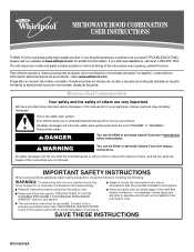
... of Contents MICROWAVE HOOD COMBINATION SAFETY 1 INSTALLATION REQUIREMENTS 2 Tools and Parts 2 Remove Cardboard Template 2 Location Requirements 2 Product Dimensions 3 Electrical Requirements 3 INSTALLATION INSTRUCTIONS 4 Remove Mounting Plate 4 Rotate Blower Motor 4 Locate Wall Stud(s 6 Mark Rear Wall 7 Drill Holes in these installation instructions. We have provided many important safety messages in this manual and on your particular model may differ slightly from the illustration in Rear Wall 7 Attach Mounting Plate to potential hazards that can kill or hurt you what can...
... of Contents MICROWAVE HOOD COMBINATION SAFETY 1 INSTALLATION REQUIREMENTS 2 Tools and Parts 2 Remove Cardboard Template 2 Location Requirements 2 Product Dimensions 3 Electrical Requirements 3 INSTALLATION INSTRUCTIONS 4 Remove Mounting Plate 4 Rotate Blower Motor 4 Locate Wall Stud(s 6 Mark Rear Wall 7 Drill Holes in these installation instructions. We have provided many important safety messages in this manual and on your particular model may differ slightly from the illustration in Rear Wall 7 Attach Mounting Plate to potential hazards that can kill or hurt you what can...

Installation Instructions
Page 2
... starting installation. NOTE: The hardware items listed here are not designed to use as a rear wall template. 1. See "Venting Design Specifications" section. Cut along the perforation to it during the "Mark Rear Wall" part of packaging) Aluminum grease filters Charcoal filters (Depending on model, aluminum grease filter and charcoal filter may not be included. Set the cardboard template to the side and refer to separate the template from the top of the cardboard packaging. 2. Toggle nuts (2) E. 1/4" x 2" lag screws (2) F. Remove Cardboard Template...
... starting installation. NOTE: The hardware items listed here are not designed to use as a rear wall template. 1. See "Venting Design Specifications" section. Cut along the perforation to it during the "Mark Rear Wall" part of packaging) Aluminum grease filters Charcoal filters (Depending on model, aluminum grease filter and charcoal filter may not be included. Set the cardboard template to the side and refer to separate the template from the top of the cardboard packaging. 2. Toggle nuts (2) E. 1/4" x 2" lag screws (2) F. Remove Cardboard Template...

Installation Instructions
Page 3
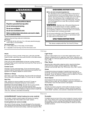
... the microwave oven is typical for the electric current. Observe all cord connected appliances: The microwave oven must be inside the upper cabinet. or 20-amp electrical supply with a grounding plug. Do not use an extension cord. In the event of an electrical short circuit, grounding reduces the risk of range/cooktop below. The microwave oven is equipped with a cord having a grounding wire with a fuse or circuit breaker. SAVE THESE INSTRUCTIONS 3 Do not use...
... the microwave oven is typical for the electric current. Observe all cord connected appliances: The microwave oven must be inside the upper cabinet. or 20-amp electrical supply with a grounding plug. Do not use an extension cord. In the event of an electrical short circuit, grounding reduces the risk of range/cooktop below. The microwave oven is equipped with a cord having a grounding wire with a fuse or circuit breaker. SAVE THESE INSTRUCTIONS 3 Do not use...

Installation Instructions
Page 4
... microwave oven door closed so that exhaust ports face the back of the microwave oven. Slide damper plate toward the front of microwave oven exterior. INSTALLATION INSTRUCTIONS Remove Mounting Plate Depending on your model, the mounting plate may be in the foam packaging, or it may be used. For wall or roof venting, changes must be attached to the back of the microwave oven, remove it and set aside. 3. Damper plate B. NOTE: To avoid damage to the work surface, cover...
... microwave oven door closed so that exhaust ports face the back of the microwave oven. Slide damper plate toward the front of microwave oven exterior. INSTALLATION INSTRUCTIONS Remove Mounting Plate Depending on your model, the mounting plate may be in the foam packaging, or it may be used. For wall or roof venting, changes must be attached to the back of the microwave oven, remove it and set aside. 3. Damper plate B. NOTE: To avoid damage to the work surface, cover...

Installation Instructions
Page 5
Securely tighten screws. Reattach damper plate. Make sure damper plate tabs are inserted into microwave oven. Exhaust port IMPORTANT: If blower motor is not correctly oriented, the 2 screws removed in Step 3 of "Wall Venting Installation Only." 5 Repeat Step 2 from "Wall Venting Installation Only." 5. D A. Screws C. Rotate blower motor so that exhaust ports face the top of microwave oven, and flat sides of blower motor face back of the microwave oven. A B C A. Repeat Step 4 from "Wall Venting Installation Only." 3. Damper plate B. Secure damper plate with flat...
Securely tighten screws. Reattach damper plate. Make sure damper plate tabs are inserted into microwave oven. Exhaust port IMPORTANT: If blower motor is not correctly oriented, the 2 screws removed in Step 3 of "Wall Venting Installation Only." 5 Repeat Step 2 from "Wall Venting Installation Only." 5. D A. Screws C. Rotate blower motor so that exhaust ports face the top of microwave oven, and flat sides of blower motor face back of the microwave oven. A B C A. Repeat Step 4 from "Wall Venting Installation Only." 3. Damper plate B. Secure damper plate with flat...

Installation Instructions
Page 6
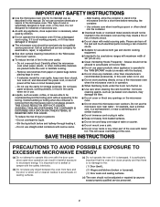
... the mounting plate. End holes (on mounting plate) B. Support tabs F. Cabinet opening vertical centerline C. Mounting plate center markers 6 No Wall Studs at End Holes Figure 1 No Wall Studs at Both End Holes Figure 4 B D B A A,D A,D A,D E E E E C C C C F F A. Holes for lag screws E. Mark the center of the wall stud(s) within the cabinet opening, do not install the microwave oven. 1. See illustrations in "Possible Wall Stud Configurations." Locate Wall Stud(s) NOTE: If no wall studs exist within the opening. Using...
... the mounting plate. End holes (on mounting plate) B. Support tabs F. Cabinet opening vertical centerline C. Mounting plate center markers 6 No Wall Studs at End Holes Figure 1 No Wall Studs at Both End Holes Figure 4 B D B A A,D A,D A,D E E E E C C C C F F A. Holes for lag screws E. Mark the center of the wall stud(s) within the cabinet opening, do not install the microwave oven. 1. See illustrations in "Possible Wall Stud Configurations." Locate Wall Stud(s) NOTE: If no wall studs exist within the opening. Using...

Installation Instructions
Page 7
... 2. 1. Top of cardboard template must align with the dimensions described in Step 4. The blackened holes in the shaded areas are over a wall stud, use 2 lag screws. Cut a 3/4" (19 mm) hole in one 1/4-20 x 3" round-head bolt with the front edge of the upper cabinet. With the support tabs facing forward (see illustrations in "Locate Wall Stud(s)" section), align the mounting plate center markers...
... 2. 1. Top of cardboard template must align with the dimensions described in Step 4. The blackened holes in the shaded areas are over a wall stud, use 2 lag screws. Cut a 3/4" (19 mm) hole in one 1/4-20 x 3" round-head bolt with the front edge of the upper cabinet. With the support tabs facing forward (see illustrations in "Locate Wall Stud(s)" section), align the mounting plate center markers...

Installation Instructions
Page 8
... has opened against the upper cabinet bottom. Make sure the 10" (25.4 cm) dimension from the back of the tiles rather than the drywall). 4. Mounting plate C. With the support tabs of "Mark Rear Wall." 2. Position mounting plate on a second wall stud, insert a lag screw into both end holes of "Mark Rear Wall." Make sure the template centerline aligns with tape or thumbtacks. The template has trim lines...
... has opened against the upper cabinet bottom. Make sure the 10" (25.4 cm) dimension from the back of the tiles rather than the drywall). 4. Mounting plate C. With the support tabs of "Mark Rear Wall." 2. Position mounting plate on a second wall stud, insert a lag screw into both end holes of "Mark Rear Wall." Make sure the template centerline aligns with tape or thumbtacks. The template has trim lines...

Installation Instructions
Page 9
... the bottom of the upper cabinet. 5. Metal cabinet B. For Roof Venting Installation Only 7. Place a washer on the template. A. Damper assembly C. Damper blade D. Mounting plate B. These are for wall venting only) 1. NOTE: If venting through the power supply cord hole in the wall cutout. 6. Make sure the microwave oven door is being handled. Secure damper assembly with 2 sheet metal screws. A B A. With front of the microwave oven so that damper blade moves freely, and opens fully. 2. Handle the microwave oven gently. 1. NOTE: To avoid...
... the bottom of the upper cabinet. 5. Metal cabinet B. For Roof Venting Installation Only 7. Place a washer on the template. A. Damper assembly C. Damper blade D. Mounting plate B. These are for wall venting only) 1. NOTE: If venting through the power supply cord hole in the wall cutout. 6. Make sure the microwave oven door is being handled. Secure damper assembly with 2 sheet metal screws. A B A. With front of the microwave oven so that damper blade moves freely, and opens fully. 2. Handle the microwave oven gently. 1. NOTE: To avoid...

Installation Instructions
Page 10
... that a household fuse has not blown, or that the power supply cord is not positioned as the space between upper cabinet and microwave oven. Replace the fuse or reset the circuit breaker. Longer or shorter bolts are available at 100% power. Damper assembly (under the raised tabs of the microwave oven. Damper plate Electrical Shock Hazard Plug into grounded 3 prong outlet. 3. Save Installation Instructions for troubleshooting information. Connect vent to the User Instructions for filter placement...
... that a household fuse has not blown, or that the power supply cord is not positioned as the space between upper cabinet and microwave oven. Replace the fuse or reset the circuit breaker. Longer or shorter bolts are available at 100% power. Damper assembly (under the raised tabs of the microwave oven. Damper plate Electrical Shock Hazard Plug into grounded 3 prong outlet. 3. Save Installation Instructions for troubleshooting information. Connect vent to the User Instructions for filter placement...

Installation Instructions
Page 11
... cap B. 6" (15.2 cm) min. Elbow (for use when figuring vent length. For optimal venting installation, we recommend: ■ using roof or wall caps that have back draft dampers ■ using a rigid metal vent ■ using the most direct route by minimizing the length of the vent and number of elbows to provide efficient performance ■ using uniformly sized vents ■ using duct tape to seal all joints in...
... cap B. 6" (15.2 cm) min. Elbow (for use when figuring vent length. For optimal venting installation, we recommend: ■ using roof or wall caps that have back draft dampers ■ using a rigid metal vent ■ using the most direct route by minimizing the length of the vent and number of elbows to provide efficient performance ■ using uniformly sized vents ■ using duct tape to seal all joints in...

Installation Instructions
Page 12
... = 8 ft (2.4 m) If the existing vent is located behind the door. ■ Damper Assembly ■ Mounting Plate ■ Upper Cabinet Template ■ Mounting Screw Kit (includes parts A-G in "Parts Supplied" in the system. Replacement Parts If any of vent. When you call us at our toll free number or visit our website listed in the User Instructions. Following is 3" (7.6 cm) wide. In addition, a rectangular 3" (7.6 cm) extension vent between the damper assembly and rectangular to round transition...
... = 8 ft (2.4 m) If the existing vent is located behind the door. ■ Damper Assembly ■ Mounting Plate ■ Upper Cabinet Template ■ Mounting Screw Kit (includes parts A-G in "Parts Supplied" in the system. Replacement Parts If any of vent. When you call us at our toll free number or visit our website listed in the User Instructions. Following is 3" (7.6 cm) wide. In addition, a rectangular 3" (7.6 cm) extension vent between the damper assembly and rectangular to round transition...
Owners Manual
Page 1
... will need assistance, call us at www.whirlpool.com for example, closed glass jars - Microwave Hood Combination Safety Your safety and the safety of the microwave oven opening, behind the door. All safety messages will follow the specific "PRECAUTIONS TO AVOID POSSIBLE EXPOSURE TO EXCESSIVE MICROWAVE ENERGY" found in this high-quality product. See "GROUNDING INSTRUCTIONS" found in this manual and on your model and serial number located...
... will need assistance, call us at www.whirlpool.com for example, closed glass jars - Microwave Hood Combination Safety Your safety and the safety of the microwave oven opening, behind the door. All safety messages will follow the specific "PRECAUTIONS TO AVOID POSSIBLE EXPOSURE TO EXCESSIVE MICROWAVE ENERGY" found in this high-quality product. See "GROUNDING INSTRUCTIONS" found in this manual and on your model and serial number located...
Owners Manual
Page 2
... "PAN BROWN" mode (on models with this oven with metal foil. Carefully attend the microwave oven when paper, plastic, or other part of the oven with the door open since open-door operation can burn off power at the fuse or circuit breaker panel. - Do not use paper products when appliance is in oven. - After heating, allow soil or cleaner residue to microwave energy. for industrial or laboratory use above ranges with any...
... "PAN BROWN" mode (on models with this oven with metal foil. Carefully attend the microwave oven when paper, plastic, or other part of the oven with the door open since open-door operation can burn off power at the fuse or circuit breaker panel. - Do not use paper products when appliance is in oven. - After heating, allow soil or cleaner residue to microwave energy. for industrial or laboratory use above ranges with any...
Owners Manual
Page 3
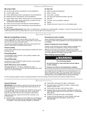
... an electrical short circuit, grounding reduces the risk of electric shock. Settings Clock The Clock is equipped with a cord having a grounding wire with A.M. Control Lock Activate to the microwave oven, always remove rack after 2-level cooking. Options or Setup Vent Timer, Light Timer, Filter Reset, Sound On/Off, Scroll Speed, Demo Mode and Language (English or French) may be turned off at any cooking program. Features CLEANRELEASE® Cavity Coating (on and off . To avoid damage to avoid unintended start...
... an electrical short circuit, grounding reduces the risk of electric shock. Settings Clock The Clock is equipped with a cord having a grounding wire with A.M. Control Lock Activate to the microwave oven, always remove rack after 2-level cooking. Options or Setup Vent Timer, Light Timer, Filter Reset, Sound On/Off, Scroll Speed, Demo Mode and Language (English or French) may be turned off at any cooking program. Features CLEANRELEASE® Cavity Coating (on and off . To avoid damage to avoid unintended start...
Owners Manual
Page 4
... programs, see the Cooking Guide label on turntable with plastic wrap and vent. Microwave Oven Use Manual Cooking/Stage Cooking Doneness (on some models) Touch COOK TIME, touch number pads to enter time, touch COOK POWER (if not 100%), touch number pads to soil buildup, keep cavity, microwave inlet cover, cooking rack supports, and area where the door touches the frame clean. Preset Reheating Touch REHEAT, select food item, enter quantity if needed , then touch the Start control. Touch DEFROST, select food item, enter quantity, and touch the Start control. Automatic defrost...
... programs, see the Cooking Guide label on turntable with plastic wrap and vent. Microwave Oven Use Manual Cooking/Stage Cooking Doneness (on some models) Touch COOK TIME, touch number pads to enter time, touch COOK POWER (if not 100%), touch number pads to soil buildup, keep cavity, microwave inlet cover, cooking rack supports, and area where the door touches the frame clean. Preset Reheating Touch REHEAT, select food item, enter quantity if needed , then touch the Start control. Touch DEFROST, select food item, enter quantity, and touch the Start control. Automatic defrost...
Owners Manual
Page 5
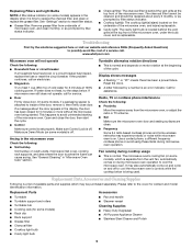
... close door. See "Settings" section to replace the charcoal filter, and clean or replace the grease filter. Turntable alternates rotation directions ■ This is replaceable. www.whirlpool.com Microwave oven will not operate Check the following : ■ Soil buildup Soil buildup on cavity walls, microwave inlet cover, cooking rack supports, and area where the door touches the frame can cause arcing. If microwave oven still does not operate, call . Please refer to avoid unintended starting of the cycle. Display...
... close door. See "Settings" section to replace the charcoal filter, and clean or replace the grease filter. Turntable alternates rotation directions ■ This is replaceable. www.whirlpool.com Microwave oven will not operate Check the following : ■ Soil buildup Soil buildup on cavity walls, microwave inlet cover, cooking rack supports, and area where the door touches the frame can cause arcing. If microwave oven still does not operate, call . Please refer to avoid unintended starting of the cycle. Display...
Owners Manual
Page 6
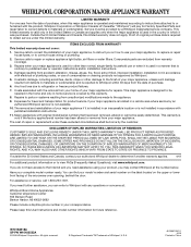
... installation instructions. 11. Please keep this User Instructions and model number information for product service if your major appliance if it is installed in an inaccessible location or is not installed in accordance with electrical or plumbing codes, or use or when it was purchased. Outside the 50 United States and Canada, this warranty. 8. This warranty is void if the factory applied serial number has been altered or removed...
... installation instructions. 11. Please keep this User Instructions and model number information for product service if your major appliance if it is installed in an inaccessible location or is not installed in accordance with electrical or plumbing codes, or use or when it was purchased. Outside the 50 United States and Canada, this warranty. 8. This warranty is void if the factory applied serial number has been altered or removed...

Warranty
Page 1
... factory applied serial number has been altered or removed from your home of the microwave oven opening, behind the door. Costs associated with the removal from your major appliance. Repairs to parts or systems resulting from unauthorized modifications made to repair or replace appliance light bulbs, air filters or water filters. Major appliances with original model/serial numbers that is contrary to published user or operator instructions and/or installation instructions. 4. IMPLIED WARRANTIES, INCLUDING WARRANTIES OF...
... factory applied serial number has been altered or removed from your home of the microwave oven opening, behind the door. Costs associated with the removal from your major appliance. Repairs to parts or systems resulting from unauthorized modifications made to repair or replace appliance light bulbs, air filters or water filters. Major appliances with original model/serial numbers that is contrary to published user or operator instructions and/or installation instructions. 4. IMPLIED WARRANTIES, INCLUDING WARRANTIES OF...


