Installation Instructions
Page 1
...;N PARA LA SECADORA A GAS DE 29" (73,7 CM) Table of Contents / Índice DRYER SAFETY 1 INSTALLATION INSTRUCTIONS 2 Tools and Parts 2 Location Requirements 3 Electrical Requirements 4 Gas Supply Requirements 4 Venting Requirements 5 Plan Vent System 6 Install Vent System 7 Install Leveling Legs 7 Level Dryer 8 Make Gas Connection 8 Connect Vent 8 Reverse Door Swing (Optional 8 Complete Installation 9 SEGURIDAD DE...
...;N PARA LA SECADORA A GAS DE 29" (73,7 CM) Table of Contents / Índice DRYER SAFETY 1 INSTALLATION INSTRUCTIONS 2 Tools and Parts 2 Location Requirements 3 Electrical Requirements 4 Gas Supply Requirements 4 Venting Requirements 5 Plan Vent System 6 Install Vent System 7 Install Leveling Legs 7 Level Dryer 8 Make Gas Connection 8 Connect Vent 8 Reverse Door Swing (Optional 8 Complete Installation 9 SEGURIDAD DE...
Installation Instructions
Page 2
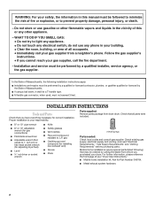
... front page of your responsibility. INSTALLATION INSTRUCTIONS Tools and Parts Check that all occupants. • Immediately call the fire department. - s Metal exhaust system hardware. 2 Parts supplied: Remove parts package from whom you purchased your dryer. WARNING: For your safety, the information in this or... in your building. • Clear the room, building, or area of all parts were included. In the State of Massachusetts, the following ) that opens to 1" (2.5 cm) or hex-head socket wrench (for adjusting dryer feet) s Level s ¼" nut driver or socket wrench s Knife s ...
... front page of your responsibility. INSTALLATION INSTRUCTIONS Tools and Parts Check that all occupants. • Immediately call the fire department. - s Metal exhaust system hardware. 2 Parts supplied: Remove parts package from whom you purchased your dryer. WARNING: For your safety, the information in this or... in your building. • Clear the room, building, or area of all parts were included. In the State of Massachusetts, the following ) that opens to 1" (2.5 cm) or hex-head socket wrench (for adjusting dryer feet) s Level s ¼" nut driver or socket wrench s Knife s ...
Installation Instructions
Page 3
... allows for the exhaust vent with automatic sensor cycles may not operate correctly if dryer is greater than 1" [2.5 cm], install Extended Dryer Feet kit, Part No. 279810.) Clothes may not tumble properly and models with elbow. At lower temperatures, the dryer might be considered. See "Venting Requirements." s Additional clearances might not shut off at...
... allows for the exhaust vent with automatic sensor cycles may not operate correctly if dryer is greater than 1" [2.5 cm], install Extended Dryer Feet kit, Part No. 279810.) Clothes may not tumble properly and models with elbow. At lower temperatures, the dryer might be considered. See "Venting Requirements." s Additional clearances might not shut off at...
Installation Instructions
Page 4
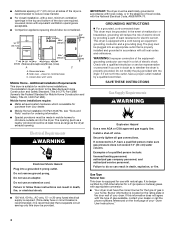
... not modify the plug provided with natural gas. Securely tighten all sides of the dryer is equipped for Mobile Home Construction and Safety, Title 24, HUD Part 280). Gas Type Natural Gas: This dryer is recommended to the Manufactured Home Construction and Safety Standard, Title 24 CFR..., Part 3280 (formerly the Federal Standard for use with the dryer: if it will reduce the risk of electric shock. If this dryer be grounded. Recessed area B. s Special provisions must have a qualified person ...
... not modify the plug provided with natural gas. Securely tighten all sides of the dryer is equipped for Mobile Home Construction and Safety, Title 24, HUD Part 280). Gas Type Natural Gas: This dryer is recommended to the Manufactured Home Construction and Safety Standard, Title 24 CFR..., Part 3280 (formerly the Federal Standard for use with the dryer: if it will reduce the risk of electric shock. If this dryer be grounded. Recessed area B. s Special provisions must have a qualified person ...
Installation Instructions
Page 5
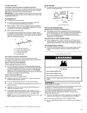
.... rating indicated on the model/serial number plate is a registered trademark of a building. Gas Supply Pressure Testing s The dryer must be disconnected from the gas specified on the model/serial rating plate for two different methods of L.P. compatible copper tubing can...;⁄₈" NPT adapter fitting between the stainless steel gas connector and the dryer gas pipe, as needed to the gas supply. s Lengths over 20 ft (6.1 m) should be made by calling Whirlpool Parts and Accessories. Burner input adjustments are recommended. WARNING: To reduce the risk ...
.... rating indicated on the model/serial number plate is a registered trademark of a building. Gas Supply Pressure Testing s The dryer must be disconnected from the gas specified on the model/serial rating plate for two different methods of L.P. compatible copper tubing can...;⁄₈" NPT adapter fitting between the stainless steel gas connector and the dryer gas pipe, as needed to the gas supply. s Lengths over 20 ft (6.1 m) should be made by calling Whirlpool Parts and Accessories. Burner input adjustments are recommended. WARNING: To reduce the risk ...
Installation Instructions
Page 6
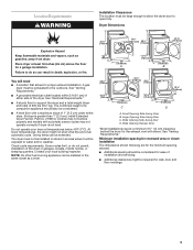
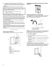
... the entire length of your installation. Remove excess flexible metal vent to avoid sagging and kinking that may be fully extended and supported when the dryer is in reduced airflow and poor performance. An exhaust hood should cap the vent to woodwork, furniture, paint, wallpaper, carpets, etc. B C D A E F... A B A. Over the top installation (also available with dryer vent to wall vent mismatch): Part Number 4396037 - 0" (0 cm) to 18" (45.72 cm) mismatch Part Number 4396011 - 18" (45.72 cm) to 29" (73.66 cm) mismatch Part Number 4396014 - 29" (73.66 cm) to connect elbows...
... the entire length of your installation. Remove excess flexible metal vent to avoid sagging and kinking that may be fully extended and supported when the dryer is in reduced airflow and poor performance. An exhaust hood should cap the vent to woodwork, furniture, paint, wallpaper, carpets, etc. B C D A E F... A B A. Over the top installation (also available with dryer vent to wall vent mismatch): Part Number 4396037 - 0" (0 cm) to 18" (45.72 cm) mismatch Part Number 4396011 - 18" (45.72 cm) to 29" (73.66 cm) mismatch Part Number 4396014 - 29" (73.66 cm) to connect elbows...
Installation Instructions
Page 8
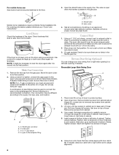
...flared male threads. Using a 4" (10.2 cm) clamp, connect vent to exhaust outlet in large part of cabinet. Make sure the vent is over the dryer exhaust outlet and inside the exhaust hood. Make sure dryer is level. 3. (On gas models) Check to be necessary to level the...is open when the handle is a recommended connection. NOTE: For L.P. D A B C A. ³⁄₈" flexible gas connector B. ³⁄₈" dryer pipe C. ³⁄₈" to ³⁄₈" pipe elbow D. ³⁄₈" pipe-to back. Insert and tighten top screws in bottom of ...
...flared male threads. Using a 4" (10.2 cm) clamp, connect vent to exhaust outlet in large part of cabinet. Make sure the vent is over the dryer exhaust outlet and inside the exhaust hood. Make sure dryer is level. 3. (On gas models) Check to be necessary to level the...is open when the handle is a recommended connection. NOTE: For L.P. D A B C A. ³⁄₈" flexible gas connector B. ³⁄₈" dryer pipe C. ³⁄₈" to ³⁄₈" pipe elbow D. ³⁄₈" pipe-to back. Insert and tighten top screws in bottom of ...
Installation Instructions
Page 9
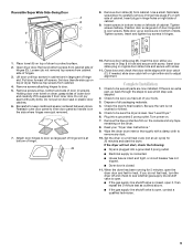
...open . Tighten screws halfway. Position door so large end of door hinge slot is an extra part, go back through the steps to adjust alignment. Place towel (A) on the dryer. 8. Open dryer door. If there is over towel on left or right within slot to see whether gas ...tight, or circuit breaker has not tripped. If you do not remove) top screws from cabinet side of dryer. Remove door strike (E) from cabinet. 4. Insert plugs in large part of dryer to door so large part of hinge slot is open , contact a qualified technician. 9 Tighten screws. Do not pry apart with...
...open . Tighten screws halfway. Position door so large end of door hinge slot is an extra part, go back through the steps to adjust alignment. Place towel (A) on the dryer. 8. Open dryer door. If there is over towel on left or right within slot to see whether gas ...tight, or circuit breaker has not tripped. If you do not remove) top screws from cabinet side of dryer. Remove door strike (E) from cabinet. 4. Insert plugs in large part of dryer to door so large part of hinge slot is open , contact a qualified technician. 9 Tighten screws. Do not pry apart with...
Parts Diagram
Page 1
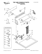
TOP AND CONSOLE PARTS For Model: WGD5200TQ0 (Designer White) 29" GAS DRYER 2−07 Litho in U.S.A. (LT) 1 Part No. W10131173 Rev.A.
TOP AND CONSOLE PARTS For Model: WGD5200TQ0 (Designer White) 29" GAS DRYER 2−07 Litho in U.S.A. (LT) 1 Part No. W10131173 Rev.A.
Parts Diagram
Page 2
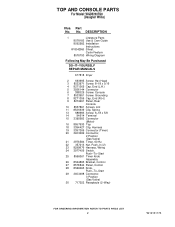
... Model: WGD5200TQ0 (Designer White) Illus. DESCRIPTION 1 Literature Parts 8578183 Use & Care Guide 8562582 Installation Instructions W10042960 Sheet, Cycle Feature 8576793 Wiring Diagram Following May Be Purchased DO−IT−YOURSELF REPAIR MANUALS 677818 Dryer 2 693995 Screw, Hex Head 3 8533971 Screw, 8−18 x 5/16 4 8271365 Cap, End (L.H.) 5 3936144 Connector 6 388326 Screw, ... Control 27 8578844 Panel, Control 28 8566065 Knob, Push−To−Start 29 3403498 Connector, 3 Position (Gas Valve) 30 717252 Receptacle (2−Way) 2 W10131173 Part No. No.
... Model: WGD5200TQ0 (Designer White) Illus. DESCRIPTION 1 Literature Parts 8578183 Use & Care Guide 8562582 Installation Instructions W10042960 Sheet, Cycle Feature 8576793 Wiring Diagram Following May Be Purchased DO−IT−YOURSELF REPAIR MANUALS 677818 Dryer 2 693995 Screw, Hex Head 3 8533971 Screw, 8−18 x 5/16 4 8271365 Cap, End (L.H.) 5 3936144 Connector 6 388326 Screw, ... Control 27 8578844 Panel, Control 28 8566065 Knob, Push−To−Start 29 3403498 Connector, 3 Position (Gas Valve) 30 717252 Receptacle (2−Way) 2 W10131173 Part No. No.
Parts Diagram
Page 4
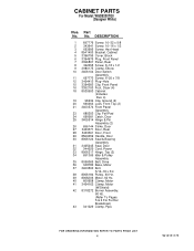
CABINET PARTS For Model: WGD5200TQ0 (Designer White) Illus. DESCRIPTION 1 697776 Screw, 10−32 x 5/8 2 343641 Screw, 10−16 x 1/2 3 693995 Screw,... 3406104 Door Switch Assembly 11 697773 Screw, 6−20 x 7/8 12 3404413 Plug−Hole 15 3394083 Clip, Front Panel 16 3392100 Foot, Dryer (4) 18 8530603 Cabinet (Includes Illus. 4) 19 98234 Clip, Ground (2) 20 690363 Lock, Front Top (2) 21 3403574 Front Panel Assembly 23 ...Shield) 42 8318272 Burner Assembly, 60 Hz. (Refer To Pages 5 & 6 For Further Breakdown) 43 341029 Clamp, Pipe 4 W10131173 Part No. No.
CABINET PARTS For Model: WGD5200TQ0 (Designer White) Illus. DESCRIPTION 1 697776 Screw, 10−32 x 5/8 2 343641 Screw, 10−16 x 1/2 3 693995 Screw,... 3406104 Door Switch Assembly 11 697773 Screw, 6−20 x 7/8 12 3404413 Plug−Hole 15 3394083 Clip, Front Panel 16 3392100 Foot, Dryer (4) 18 8530603 Cabinet (Includes Illus. 4) 19 98234 Clip, Ground (2) 20 690363 Lock, Front Top (2) 21 3403574 Front Panel Assembly 23 ...Shield) 42 8318272 Burner Assembly, 60 Hz. (Refer To Pages 5 & 6 For Further Breakdown) 43 341029 Clamp, Pipe 4 W10131173 Part No. No.
Parts Diagram
Page 8
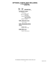
OPTIONAL PARTS (NOT INCLUDED) For Model: WGD5200TQ0 (Designer White) Illus. Part No. DESCRIPTION ACCESSORY PARTS 279948 Kit, Dryer Repair 8522199 Kit, Dryer Vent Testing 346764 Kit, Hold−Down (Gas Dryer Mobile Home Installation) 689790 Dry Rack PAINT, TOUCH−UP (1/2oz.) 72017 White PAINT, PRESSURIZED SPRAY (12 oz.) 350930 White 350938 Primer, Gray PAINT, BULK (1 qt.) 799344 White (Uncut) 8 W10131173 No.
OPTIONAL PARTS (NOT INCLUDED) For Model: WGD5200TQ0 (Designer White) Illus. Part No. DESCRIPTION ACCESSORY PARTS 279948 Kit, Dryer Repair 8522199 Kit, Dryer Vent Testing 346764 Kit, Hold−Down (Gas Dryer Mobile Home Installation) 689790 Dry Rack PAINT, TOUCH−UP (1/2oz.) 72017 White PAINT, PRESSURIZED SPRAY (12 oz.) 350930 White 350938 Primer, Gray PAINT, BULK (1 qt.) 799344 White (Uncut) 8 W10131173 No.


