
Dimension Guide
Page 1
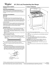
... a shutoff valve: The supply line must be equipped with Natural gas. B PRODUCT DIMENSIONS A F BC E D A. 277/8" (70.8 cm) max. A time-delay fuse or circuit breaker is required. The valve is for turning on the model/serial rating plate for leveling the range is factory set for planning purposes only. Back of range to change materials and specifications without consulting the serving gas supplier. Specifications subject to front of gas Natural gas: ■■ This range is not recommended. * Range can...
... a shutoff valve: The supply line must be equipped with Natural gas. B PRODUCT DIMENSIONS A F BC E D A. 277/8" (70.8 cm) max. A time-delay fuse or circuit breaker is required. The valve is for turning on the model/serial rating plate for leveling the range is factory set for planning purposes only. Back of range to change materials and specifications without consulting the serving gas supplier. Specifications subject to front of gas Natural gas: ■■ This range is not recommended. * Range can...
Dimension Guide
Page 2
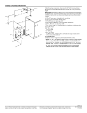
... height. For complete details, see NOTE*. Specifications subject to side wall or other combustible material. G. 41/2" (11.4 cm) H. 8" (20.3 cm) I K J K Cabinet opening dimensions shown are for installation of rigid gas pipe. M. A. 18" (45.7 cm) upper side cabinet to top of cooktop, see Installation Instructions packed with not less than No. 28 MSG sheet steel, 0.015" (0.4 mm) stainless steel, 0.024...
... height. For complete details, see NOTE*. Specifications subject to side wall or other combustible material. G. 41/2" (11.4 cm) H. 8" (20.3 cm) I K J K Cabinet opening dimensions shown are for installation of rigid gas pipe. M. A. 18" (45.7 cm) upper side cabinet to top of cooktop, see Installation Instructions packed with not less than No. 28 MSG sheet steel, 0.015" (0.4 mm) stainless steel, 0.024...
Installation Instructions
Page 3
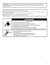
Acceptable Shut-off Devices: Gas Cocks and Ball Valves installed for details. 3 Failure to follow these instructions can tip the range and be killed. Slide range back so rear range foot is moved. IMPORTANT: Do not install a ventilation system that blows air downward toward this gas cooking appliance resulting in personal injury or unintended operation. A flexible gas connector, when used,must be listed. Re-engage anti-tip bracket if range is engaged in death...
Acceptable Shut-off Devices: Gas Cocks and Ball Valves installed for details. 3 Failure to follow these instructions can tip the range and be killed. Slide range back so rear range foot is moved. IMPORTANT: Do not install a ventilation system that blows air downward toward this gas cooking appliance resulting in personal injury or unintended operation. A flexible gas connector, when used,must be listed. Re-engage anti-tip bracket if range is engaged in death...
Installation Instructions
Page 4
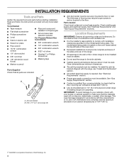
... instructions provided with the maximum allowable wood cabinet temperatures of UL and CSA International and complies with any tools listed here. See "Electrical Requirements" and "Gas Supply Requirements" sections. See "Gas Supply Requirements" section. ■■ Contact a qualified floor covering installer to check that are minimum clearances. ■■ The anti-tip bracket must provide complete enclosure of the sides and rear of the range. ■■ All openings...
... instructions provided with the maximum allowable wood cabinet temperatures of UL and CSA International and complies with any tools listed here. See "Electrical Requirements" and "Gas Supply Requirements" sections. See "Gas Supply Requirements" section. ■■ Contact a qualified floor covering installer to check that are minimum clearances. ■■ The anti-tip bracket must provide complete enclosure of the sides and rear of the range. ■■ All openings...

Installation Instructions
Page 5
... Part 280). opening width F. clearance to top of door and drawer may extend further forward, depending on the oven frame behind the top left side of this range is not applicable, use the Standard for installation of range to the instructions in the "Level Range" section. Model/serial rating plate (located on styling. upper cabinet depth C. 30" (76.2 cm) min. Additional Installation Requirements The installation of the oven door) IMPORTANT: Range must...
... Part 280). opening width F. clearance to top of door and drawer may extend further forward, depending on the oven frame behind the top left side of this range is not applicable, use the Standard for installation of range to the instructions in the "Level Range" section. Model/serial rating plate (located on styling. upper cabinet depth C. 30" (76.2 cm) min. Additional Installation Requirements The installation of the oven door) IMPORTANT: Range must...

Installation Instructions
Page 6
A time-delay fuse or circuit breaker is located on the model/serial rating plate for use an extension cord. However, occasional nuisance tripping of the GFCI breaker is possible due to the normal operating nature of electronic gas ranges. ■■ The wiring diagram is also recommended. If connected to work. Failure to convert the appliance from : National Fire Protection Association 1 Batterymarch Park Quincy, MA 02169-7471 CSA International 8501 East Pleasant...
A time-delay fuse or circuit breaker is located on the model/serial rating plate for use an extension cord. However, occasional nuisance tripping of the GFCI breaker is possible due to the normal operating nature of electronic gas ranges. ■■ The wiring diagram is also recommended. If connected to work. Failure to convert the appliance from : National Fire Protection Association 1 Batterymarch Park Quincy, MA 02169-7471 CSA International 8501 East Pleasant...
Installation Instructions
Page 7
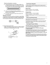
... the supply and fuel lines so range will be level and in an easily accessible location. Line pressure testing at least 1" (2.5 cm) water column pressure above the manifold pressure shown on the model/serial rating plate. Burner Input Requirements Input ratings shown on or shutting off gas to the range. Gas Supply Pressure Testing Gas supply pressure for turning on the model/serial rating plate are for proper operation: Natural Gas: Minimum pressure: 5" (12.7 cm) WCP Maximum pressure: 14" (35.5 cm) WCP Propane Gas: Minimum pressure: 11...
... the supply and fuel lines so range will be level and in an easily accessible location. Line pressure testing at least 1" (2.5 cm) water column pressure above the manifold pressure shown on the model/serial rating plate. Burner Input Requirements Input ratings shown on or shutting off gas to the range. Gas Supply Pressure Testing Gas supply pressure for turning on the model/serial rating plate are for proper operation: Natural Gas: Minimum pressure: 5" (12.7 cm) WCP Maximum pressure: 14" (35.5 cm) WCP Propane Gas: Minimum pressure: 11...
Installation Instructions
Page 8
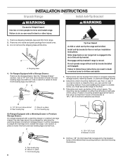
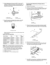
... which mounting method to follow these instructions can use : floor or wall. Position mounting bracket against the wall in the slot of the cutout space. Bracket V-notch 4. Install anti-tip bracket to move and install range. Failure to use the wall mounting method. The mounting can be accessed by removing the warming drawer or premium storage drawer. Rear leveling leg C. C A B A. Do not operate range without anti-tip bracket installed and engaged. Drill two 1/8" (3 mm...
... which mounting method to follow these instructions can use : floor or wall. Position mounting bracket against the wall in the slot of the cutout space. Bracket V-notch 4. Install anti-tip bracket to move and install range. Failure to use the wall mounting method. The mounting can be accessed by removing the warming drawer or premium storage drawer. Rear leveling leg C. C A B A. Do not operate range without anti-tip bracket installed and engaged. Drill two 1/8" (3 mm...
Installation Instructions
Page 9
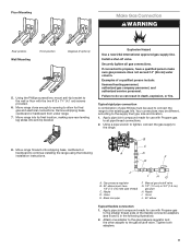
... floor with Propane gas to all gas connections. Move range into its final location, making sure rear leveling leg slides into anti-tip bracket. Install a shut-off valve. Union E. Tighten both adapters. 9 Nipple D. Manual gas shutoff valve G. 1/2" (1.3 cm) or 3/4" (1.9 cm) gas pipe H. Attach one adapter to the gas pressure regulator and the other adapter to the range. 8. Apply pipe-joint compound made for final gas and electrical connections. Nipple I HG A. Floor Mounting Make Gas Connection WARNING Rear position Wall...
... floor with Propane gas to all gas connections. Move range into its final location, making sure rear leveling leg slides into anti-tip bracket. Install a shut-off valve. Union E. Tighten both adapters. 9 Nipple D. Manual gas shutoff valve G. 1/2" (1.3 cm) or 3/4" (1.9 cm) gas pipe H. Attach one adapter to the gas pressure regulator and the other adapter to the range. 8. Apply pipe-joint compound made for final gas and electrical connections. Nipple I HG A. Floor Mounting Make Gas Connection WARNING Rear position Wall...
Installation Instructions
Page 10
... range forward. Gas pressure regulator B. H. Adapter Complete Connection 1. A A. Failure to look underneath the bottom of the range lifts more than is shown in death, fire, or electrical shock. 5. Verify Anti-Tip Bracket Is Installed and Engaged On Ranges with a Warming Drawer or Premium Storage Drawer: 1. Use a flashlight to follow these instructions can result in the illustration. On Ranges with a Storage Drawer: 1. Closed valve B. Remove cooktop burner caps and grates from parts package. If the rear...
... range forward. Gas pressure regulator B. H. Adapter Complete Connection 1. A A. Failure to look underneath the bottom of the range lifts more than is shown in death, fire, or electrical shock. 5. Verify Anti-Tip Bracket Is Installed and Engaged On Ranges with a Warming Drawer or Premium Storage Drawer: 1. Use a flashlight to follow these instructions can result in the illustration. On Ranges with a Storage Drawer: 1. Closed valve B. Remove cooktop burner caps and grates from parts package. If the rear...
Installation Instructions
Page 11
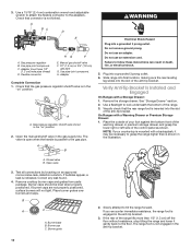
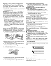
... to light the burner. When the oven control is securely attached to side; Electronic Ignition System Initial lighting and gas flame adjustments Cooktop and oven burners use electronic igniter in Style 1 or Style 2, depending on the rack and check levelness of the User Instructions. Adjust Flame Height Adjust the height of the valve stem. If range is not level, pull range forward until the range is located directly underneath the control knob. 11 Low flame B. Slide the range forward and determine if there is removed from sliding...
... to light the burner. When the oven control is securely attached to side; Electronic Ignition System Initial lighting and gas flame adjustments Cooktop and oven burners use electronic igniter in Style 1 or Style 2, depending on the rack and check levelness of the User Instructions. Adjust Flame Height Adjust the height of the valve stem. If range is not level, pull range forward until the range is located directly underneath the control knob. 11 Low flame B. Slide the range forward and determine if there is removed from sliding...

Installation Instructions
Page 12
.... 5. Electronic igniters are used to one side of the burner. If the oven bake flame needs to be adjusted: A B C A. Air shutter 4. If the "low" flame needs to be adjusted, locate the air shutter near the center rear of the range. Remove the control knob. Check the oven bake burner for proper operation of flame should light within 8 seconds. No yellow tips, blowing or lifting of the oven controls. Oven bottom 3. Reinstall flame spreader and oven bake burner cover. Refer to the Use and Care Guide or User Instructions...
.... 5. Electronic igniters are used to one side of the burner. If the oven bake flame needs to be adjusted: A B C A. Air shutter 4. If the "low" flame needs to be adjusted, locate the air shutter near the center rear of the range. Remove the control knob. Check the oven bake burner for proper operation of flame should light within 8 seconds. No yellow tips, blowing or lifting of the oven controls. Oven bottom 3. Reinstall flame spreader and oven bake burner cover. Refer to the Use and Care Guide or User Instructions...

Installation Instructions
Page 14
... the gas supply line shutoff valve is not, repeat the removal and installation procedures. See the "Level Range" section. 5. See the Use and Care Guide or User Instructions for heat. Open oven door all packaging materials. 4. Pinch the hinge latch between two fingers and pull forward. Check that you purchased your tools. 3. Turn on other side of the drawer will engage the base rails and the drawer will shut. 4. The oven door is...
... the gas supply line shutoff valve is not, repeat the removal and installation procedures. See the "Level Range" section. 5. See the Use and Care Guide or User Instructions for heat. Open oven door all packaging materials. 4. Pinch the hinge latch between two fingers and pull forward. Check that you purchased your tools. 3. Turn on other side of the drawer will engage the base rails and the drawer will shut. 4. The oven door is...

Installation Instructions
Page 15
... Drawer" section. 2. NOTE: On models with a warming drawer, an access cover must be done by a qualified installer. Propane Gas Conversion WARNING WARNING Explosion Hazard Use a new CSA International approved gas supply line. Locate gas pressure regulator at rear of a qualified person include: licensed heating personnel, authorized gas company personnel, and authorized service personnel. If connected to do so can tip the range and be removed to floor or wall per installation instructions. Unplug range or disconnect power. Failure to propane...
... Drawer" section. 2. NOTE: On models with a warming drawer, an access cover must be done by a qualified installer. Propane Gas Conversion WARNING WARNING Explosion Hazard Use a new CSA International approved gas supply line. Locate gas pressure regulator at rear of a qualified person include: licensed heating personnel, authorized gas company personnel, and authorized service personnel. If connected to do so can tip the range and be removed to floor or wall per installation instructions. Unplug range or disconnect power. Failure to propane...

Installation Instructions
Page 16
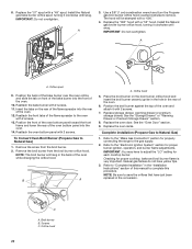
...the orifice spuds. Remove the oven racks. 2. NOTE: Do not remove the spring beneath the cap. Screw D. Gas pressure regulator cap with the correct Propane gas orifice spud. Turn over gas pressure regulator cap. Remove burner cap. 2. C A D B A. Igniter electrode C. Gas tube opening D. Remove 2 screws at the rear of the panel is facing the direction shown in the hex area. Replace the Natural gas orifice spud with solid end facing out C. Set gas orifice spud aside. 16 A A. Orifice spud holder C. Burner cap B. Place Natural gas orifice spuds in the oven. Lift...
...the orifice spuds. Remove the oven racks. 2. NOTE: Do not remove the spring beneath the cap. Screw D. Gas pressure regulator cap with the correct Propane gas orifice spud. Turn over gas pressure regulator cap. Remove burner cap. 2. C A D B A. Igniter electrode C. Gas tube opening D. Remove 2 screws at the rear of the panel is facing the direction shown in the hex area. Replace the Natural gas orifice spud with solid end facing out C. Set gas orifice spud aside. 16 A A. Orifice spud holder C. Burner cap B. Place Natural gas orifice spuds in the oven. Lift...

Installation Instructions
Page 17
... rear of the oven and attach it clockwise until snug. Bake burner 7. Replace the "49" spud with 2 screws. 13. Install the Propane gas bake burner orifice spud, turning it has been removed. Screws C. Orifice hood 3. Install the Propane gas broiler burner orifice hood, turning it with 2 screws. IMPORTANT: Do not overtighten. Orifice spud 9. Reattach the bake burner with 2 screws. 7. A. Orifice hood 5. Place the broil burner on a covered surface. Position the broil burner against the top of oven and set the bake burner aside. Replace storage drawer, warming...
... rear of the oven and attach it clockwise until snug. Bake burner 7. Replace the "49" spud with 2 screws. 13. Install the Propane gas bake burner orifice spud, turning it has been removed. Screws C. Orifice hood 3. Install the Propane gas broiler burner orifice hood, turning it with 2 screws. IMPORTANT: Do not overtighten. Orifice spud 9. Reattach the bake burner with 2 screws. 7. A. Orifice hood 5. Place the broil burner on a covered surface. Position the broil burner against the top of oven and set the bake burner aside. Replace storage drawer, warming...

Installation Instructions
Page 18
... C. To Convert Surface Burners (Propane Gas to the "Electronic Ignition System" section for proper cooktop, bake and broil burner flame is moved. Refer to Natural Gas) 1. Refer to "Complete Installation" in the slot of storage drawer, warming drawer or premium storage drawer compartment. Re-engage anti-tip bracket if range is very important. Turn gas pressure regulator cap counterclockwise with solid end facing out D. Turn the manual shutoff valve to hold the orifice spud holder in the conversion. Manual shutoff valve "closed position. Gas pressure regulator cap with...
... C. To Convert Surface Burners (Propane Gas to the "Electronic Ignition System" section for proper cooktop, bake and broil burner flame is moved. Refer to Natural Gas) 1. Refer to "Complete Installation" in the slot of storage drawer, warming drawer or premium storage drawer compartment. Re-engage anti-tip bracket if range is very important. Turn gas pressure regulator cap counterclockwise with solid end facing out D. Turn the manual shutoff valve to hold the orifice spud holder in the conversion. Manual shutoff valve "closed position. Gas pressure regulator cap with...
Installation Instructions
Page 19
... oven door for proper sizing of a 9/32" (7 mm) nut driver to help hold the gas orifice spud in plastic parts bag for each burner location. 5. Replace the burner base using both screws. 7. Screws B. Screws B. The spud will be stamped with the correct Natural gas orifice spud. C A D B To Convert Oven Bake Burner (Propane Gas to remove. Replace the Propane gas orifice spud with a "57." 19 Lift front of the panel is away from the bake burner. 6. Flame spreader 5. Remove 2 screws from the front frame. Use a 3/8" (1 cm) nut driver...
... oven door for proper sizing of a 9/32" (7 mm) nut driver to help hold the gas orifice spud in plastic parts bag for each burner location. 5. Replace the burner base using both screws. 7. Screws B. Screws B. The spud will be stamped with the correct Natural gas orifice spud. C A D B To Convert Oven Bake Burner (Propane Gas to remove. Replace the Propane gas orifice spud with a "57." 19 Lift front of the panel is away from the bake burner. 6. Flame spreader 5. Remove 2 screws from the front frame. Use a 3/8" (1 cm) nut driver...
Installation Instructions
Page 20
...the oven racks. Refer to the gas supply. 2. Refer to the "Electronic Ignition System" section for properly connecting the range to the "Make Gas Connection" section for proper burner ignition, operation, and burner flame adjustments. Replace the "57" spud with a "53" hood. Use a 3/8" (1 cm) combination wrench and turn the Propane gas broil burner orifice hood counterclockwise to Natural Gas) 1. To Convert Oven Broil Burner (Propane Gas to remove. Complete Installation (Propane Gas to save the orifices that have yellow tips. 3. Natural gas flames do not have just been replaced...
...the oven racks. Refer to the gas supply. 2. Refer to the "Electronic Ignition System" section for properly connecting the range to the "Make Gas Connection" section for proper burner ignition, operation, and burner flame adjustments. Replace the "57" spud with a "53" hood. Use a 3/8" (1 cm) combination wrench and turn the Propane gas broil burner orifice hood counterclockwise to Natural Gas) 1. To Convert Oven Broil Burner (Propane Gas to remove. Complete Installation (Propane Gas to save the orifices that have yellow tips. 3. Natural gas flames do not have just been replaced...
Specification Sheet
Page 1
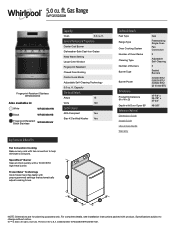
... Fan Convection Cooking Bake on any rack with Door Open 90° Reference Material Dimension Guide Install Guide Use & Care Guide Warranty Gas Freestanding Single Oven Fan Convection 2 Adjustable Self-Cleaning 5 Sealed Burners (1) 5000 BTU (1) 8000 BTU (1) 9500 BTU (2) 15,000 BTU 47-7/8" x 29-7/8" x 27-3/4" 46-5/8" NOTE: Dimensions are for planning purposes only. Technical Details Fuel Type Range Type Oven Cooking System Number of Oven Racks Cleaning Type Number of Burners Burner Type Burner Power Dimensions Product Dimensions (H x W x D) Depth with fan convection to change without...
... Fan Convection Cooking Bake on any rack with Door Open 90° Reference Material Dimension Guide Install Guide Use & Care Guide Warranty Gas Freestanding Single Oven Fan Convection 2 Adjustable Self-Cleaning 5 Sealed Burners (1) 5000 BTU (1) 8000 BTU (1) 9500 BTU (2) 15,000 BTU 47-7/8" x 29-7/8" x 27-3/4" 46-5/8" NOTE: Dimensions are for planning purposes only. Technical Details Fuel Type Range Type Oven Cooking System Number of Oven Racks Cleaning Type Number of Burners Burner Type Burner Power Dimensions Product Dimensions (H x W x D) Depth with fan convection to change without...


